Page 25 of 364
ENGINE – CYLINDER HEAD GASKET
11-19
� �
D� �
Fitting the oil return pipe gasket
Replace the gasket with a new one, and fit it to the protruded part
shown in the diagram.
Note:
For the oil return pipe gasket on the turbocharger side, there is no
direction for slotting it in.
� �
E� �
Fitting the eyebolts
Caution
When tightening the eyebolts, hold the oil pipe joint in place
with a spanner so that it does not turn round as the eyebolts
are tightened.
Protrusion
Page 83 of 364

INTAKE & EXHAUST – EXHAUST MANIFOLD15-9
Removal procedure
1. Exhaust manifold heat protector
2. Air pipe ASSY connection
3. O
2sensor
4. Turbocharger heat protector
5. Turbocharger water feed pipe connection
6. Gasket
7. Water hose connection
8. Oil feed pipe
9. Gasket
10. Starter
11.Oil return pipe
12. Oil return pipe gasket (turbocharger side)
13. Oil return pipe gasket (oil pan side)14. Vacuum hose connection
15. Air outlet fitting
16. Air outlet fitting gasket
17. Exhaust fitting bracket
18. Turbocharger and exhaust fitting ASSY
19. Turbocharger ASSY
20. Exhaust fitting gasket
21. Exhaust fitting
22. Turbocharger gasket
23. Turbocharger water return pipe
24. Gasket
25. Exhaust manifold
26. Exhaust manifold gasket
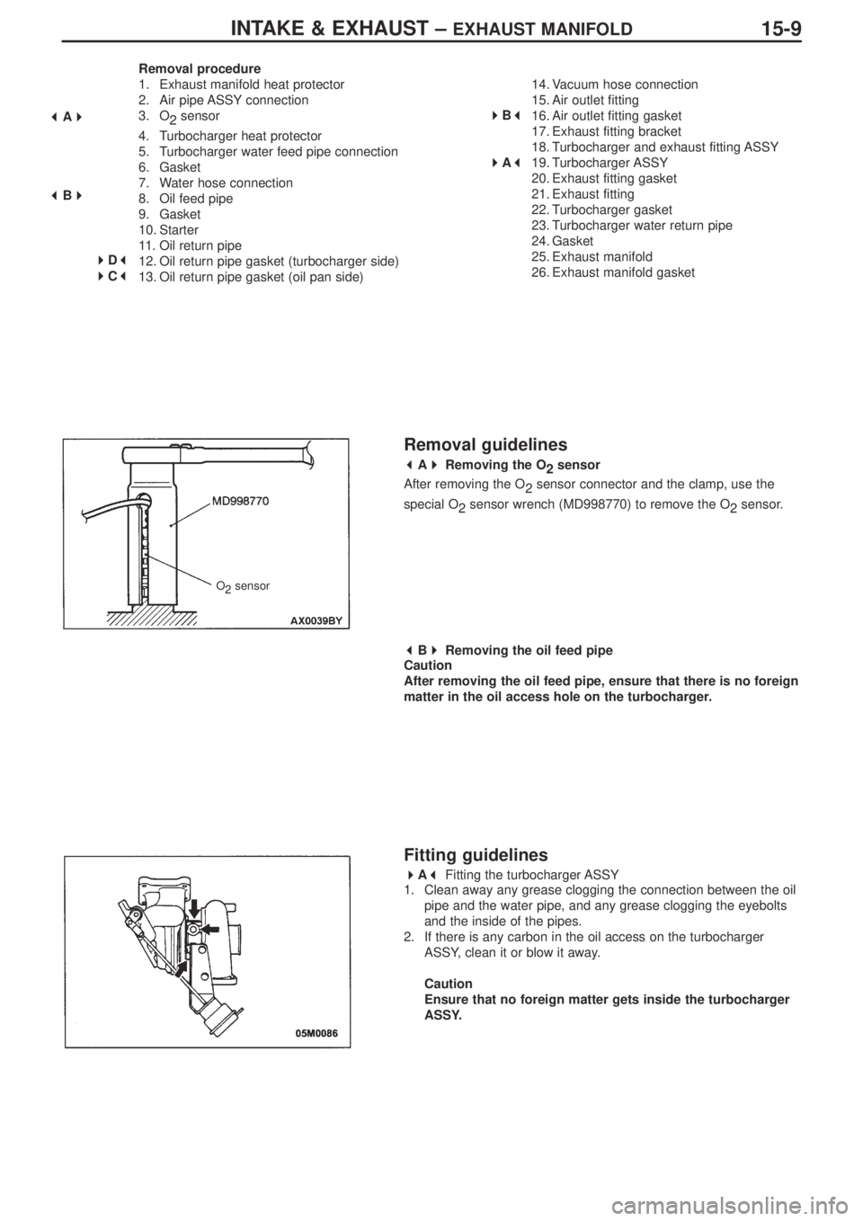
Removal guidelines
� �
A� �
Removing the O
2sensor
After removing the O
2sensor connector and the clamp, use the
special O
2 sensor wrench (MD998770) to remove the O
2sensor.
� �
B� �
Removing the oil feed pipe
Caution
After removing the oil feed pipe, ensure that there is no foreign
matter in the oil access hole on the turbocharger.
Fitting guidelines
� �
A� �
Fitting the turbocharger ASSY
1. Clean away any grease clogging the connection between the oil
pipe and the water pipe, and any grease clogging the eyebolts
and the inside of the pipes.
2. If there is any carbon in the oil access on the turbocharger
ASSY, clean it or blow it away.
Caution
Ensure that no foreign matter gets inside the turbocharger
ASSY.
� �
A� �
� �
B� �
�
�
D� �
� �
C� �
�
�
B� �
� �
A� �
O
2sensor
Page 84 of 364
INTAKE & EXHAUST – EXHAUST MANIFOLD15-10
� �
B� �
Fitting the air outlet fitting gasket
Fit the gasket so that the protruding part is in the position located in
the diagram.
� �
C� �
Fitting the oil return pipe gasket (oil pan side)
Fit so that the printed side of the gasket is on the oil pan side.
� �
D� �
Fitting the oil return pipe gasket (turbocharger side)
Fit so that the printed side of the gasket is on the turbocharger side.turbocharger
protruding part
view “A”
view “A”
print
print
gasket
gasket
3. Apply some fresh engine oil via the fitting hole for the oil feed
pipe in the turbocharger ASSY.
Page 126 of 364

194G6 – ROCKER ARM / CAMSHAFT
Installation Service Point
Installation of OCV filter
Note :
Before fitting the filter, check that it is clean and is not damaged
or deformed in any way.
Installation of eye bolt
Note :
The oil pump may be damaged if the oil pipe joint turns with the
eye bolt when it is fitted.
Hold the oil pipe joint in place with a spanner, etc., and then tighten
the eye bolt to the specified torque 42 ±2 N-m.
Installation of cam position sensor
support
1. Wipe away all traces of the old liquid gasket left on the cam
position sensor support and the cylinder head.
2. Apply a 3 mm-thick coat of the liquid gasket to the parts of the
cam position sensor support indicated on the diagram.
Liquid Gasket
Product name : MZ100191 or equivalent
Installation of cam position sensing
cylinder
1. Set the camshaft to the top dead centre for No.1.
2. Install the various vanes of the cam position sensing cylinder at
the positions indicated on the diagram.
Installation of cover / gasket
1. Before installing the cover and gasket, put the camshaft to the
No.1 top dead centre position, and check that the vanes of the
respective sensing cylinders are located in the positions shown in
the diagram.
Eye bolt
Hold with
spanner, etc.
Oil pipe joint
Exhaust sideIntake side
Exhaust side
Exhaust sideIntake side
Intake sideVane
Vane
Vane
Vane VaneVane
Vane Vane
Vane
(large) Vane
(large) Vane
(small)
Vane
(small)
�A�*
�B� �*
�C�
�*
�D�
�*
�E�
�*
Page 128 of 364

214G6 – OIL PUMP / SUMP
Oil Pump / Oil Pan
Removal and Installation
Removal Sequence
1. Drain plug
2. Drain plug gasket
3. Oil filter
4. Oil pan
5. Oil screen
6. Oil screen gasket
7. Baffle plate
8. Oil pressure switch
9. Oil cooler bypass valve
10. Relief plug
11.Gasket
12. Relief spring
13. Relief plunger
14. Oil filter bracket
15. Oil filter bracket gasket
16. Plug cap
17. O ring18. Flange bolt
19. Oil pump case
20. Oil pump case gasket
21. Oil pump cover
22. Oil pump driven gear
23. Oil pump drive gear
24. Crankshaft front oil seal
25. Counterbalance shaft oil seal
26. Oil pump oil seal
27. Counterbalance shaft, right
28. Counterbalance shaft, left
29. Counterbalance shaft front bearing
30. Counterbalance shaft rear bearing, right
31. Counterbalance shaft rear bearing, left
Apply engine oil to all
sliding parts before
installing.
�
* 1�*
�
* 1�*
�
* 1�*
�
* 1�*
�
* 1�*
�
* 1�*
�
* 1�*
�
* 1�*
�
* 1�* �
* 1�*
�
* 1�*
�
* 1�*
�
* 1�*
�
* 1�* �
* 1�*
�* * 1�
�
* * 1��
* * 1�
�
* * 1�
�
* * 1�
�* * 1�