Page 31 of 364

ENGINE – TIMING BELT, TIMING BELT B
11-25
� �
C� �
Fitting the crankshaft sensing blade and the
crankshaft sprocket
1. Clean, and remove any grease from the crankshaft sensing
blade, the crankshaft sprocket, and the surface of the crankshaft
to which the crankshaft sprocket will be fitted.
2. Fit the crankshaft sensing blade and the crankshaft sprocket in
the direction shown in the diagram.
3. Clean the screw hole in the crankshaft.
4. Place the washer with the larger surface side in the direction as
shown in the diagram, and fit it to the crankshaft bolt.
5. Apply a small quantity of engine oil to the top and to the screw
thread parts of the crankshaft bolt.
6. In the same way as when it was removed, hold the crankshaft
sprocket using the special tool, and tighten the crankshaft bolt to
the specified torque.
Tightening torque: 167 N·m
� �
D� �
Fitting the auto-tensioner
1. If the auto-tensioner rod remains in an extended state, install it
using the following procedure.
(1) Using a press or a vice, slowly compress the auto-
tensioner rod and align the rod with setting hole A and the
tensioner cylinder with setting hole B.
Caution
If the speed of compression is too fast, there is a
chance that the rod may break, so carry out this
operation slowly.
(2) Insert a wire or pin into the aligned holes.
Note
If a brand new or a replacement auto-tensioner is being
used, use a pin to set the auto-tensioner in place.
2. Fit the auto-tensioner into the engine and tighten the mounting
bolt to the specified torque. Do not remove the wire or pin until
the tension of the timing belt has been adjusted.
Tightening torque: 23 ± 3 N·m
� �
E� �
Fitting the tensioner pulley
As a temporary step, fit the tensioner pulley as shown in the
diagram.
Front of engine
washer
crankshaft sprocket
clean
here
crankshaft
crankshaft boltcrankshaft
sensing
blade
remove
grease
wire or pin
tensioner pulley holes
Page 56 of 364

13A-16MPI – TROUBLESHOOTING
Check the purge control solenoid valve (Refer to Section
17: Checking the exhaust gas purification system)
MUT-II/III Service data
•No.11 O
2sensor (Ref: P13A-83)*
Refer to the diagnosis code classification table (P13A-6)MUT-II/III diagnosis code
•Is the diagnosis code displayed?
Check the timing of ignition (Ref Section 11, Engine
tuning)
Check the sound made by the injector (using a
soundscope)
Check the crank angle sensor and the fitting of the timing
belt cover
If there is abnormality in the exhaust gases and code
Nos. P0201~P0204 are recorded, check the injector
system
If abnormal sensor data is recorded, carry out inspections
for each diagnosis code in order (Ref: P13A-6)
Replace the purge control solenoid valve
Code No.P0130: O
2sensor system inspection (Ref:
P13A-16)*
Go on to next page.
MUT-II/III Service data
•No.13: Intake air temperature sensor
•No.14: TPS
•No.21: Water temperature sensor
•No.25: Atmospheric pressure sensor
•No.95: MAP sensor
(Ref: P13A-24)
Proceed to OK if all service data levels are normal.
Proceed via NG even if only one of the service data
levels is abnormal.
*: Refer to the 03-1 Service Manual for the Lancer Evolution VIII (No.1036K07)
NO
OK
OK
OK
OK
OK
YES
NG
NG
NG
NG
Inspection procedureFault to be checkedReference page
11
Engine seems hesitant
13A-16Acceleration malfunction
Engine seems to stumble
Engine has a power surge
15Mis-timed ignition13A-18
35Inter-cooler water spray circuit system13A-19
37No.2 waste gate solenoid valve system13A-21
38Air temperature sensor system13A-22
Engine seems hesitant, acceleration malfunction, engine
seems to stumble, engine has a power surgeProbable causes of the malfunction
Probable causes of the malfunction are noted in the right hand
column.•Malfunction of the air/fuel mixing control system
•Malfunction of the ignition system
•Malfunction of the fuel system
•Malfunction of the intake system
•Malfunction of the exhaust gas purification system
•Failure of compression pressure
•Malfunction of the turbocharger system
5. Inspection procedure for each type of fault
Inspection procedure 11
4. Checklist of faults
Page 111 of 364

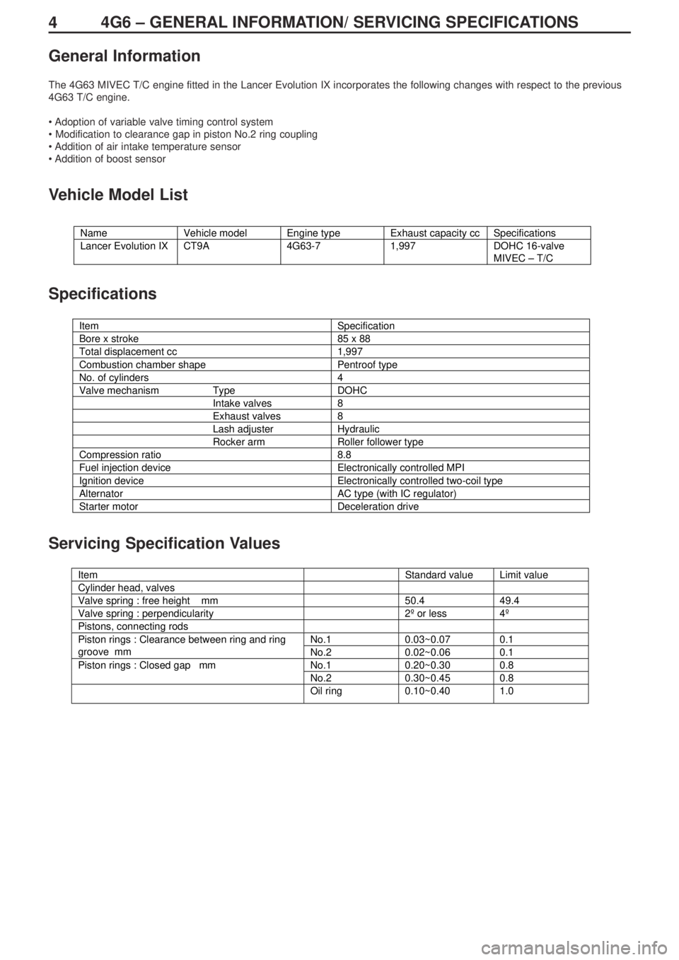
44G6 – GENERAL INFORMATION/ SERVICING SPECIFICATIONS
General Information
The 4G63 MIVEC T/C engine fitted in the Lancer Evolution IX incorporates the following changes with respect to the previous
4G63 T/C engine.
• Adoption of variable valve timing control system
• Modification to clearance gap in piston No.2 ring coupling
• Addition of air intake temperature sensor
• Addition of boost sensor
Vehicle Model List
Specifications
Servicing Specification Values
Name Vehicle model Engine type Exhaust capacity cc Specifications
Lancer Evolution IX CT9A 4G63-7 1,997 DOHC 16-valve
MIVEC – T/C
Item Specification
Bore x stroke 85 x 88
Total displacement cc 1,997
Combustion chamber shape Pentroof type
No. of cylinders 4
Valve mechanism Type DOHC
Intake valves 8
Exhaust valves 8
Lash adjuster Hydraulic
Rocker arm Roller follower type
Compression ratio 8.8
Fuel injection device Electronically controlled MPI
Ignition device Electronically controlled two-coil type
Alternator AC type (with IC regulator)
Starter motor Deceleration drive
g
Item Standard value Limit value
Cylinder head, valves
Valve spring : free height mm 50.4 49.4
Valve spring : perpendicularity 2º or less 4º
Pistons, connecting rods
No.1 0.03~0.07 0.1Piston rings : Clearance between ring and ring
groove mm
No.2 0.02~0.06 0.1
No.1 0.20~0.30 0.8Piston rings : Closed gap mm
No.2 0.30~0.45 0.8
Oil ring 0.10~0.40 1.0