Page 24 of 364

ENGINE – CYLINDER HEAD GASKET11-18
3. Use the special wrench for cylinder head bolts (MB991654) to
(loosely) tighten the bolts in the following order.
(1) In the order shown in the diagram, tighten the bolts to
78 ± 2 N•m.
(2) In reverse order to that shown in the diagram, completely loosen
the bolts.
(3) In the order shown in the diagram, tighten the bolts to
20 ± 2 N•m.
(4) Make a paint mark on the top of the cylinder head bolt, and on
the cylinder head, and tighten them to 90° as shown in the
diagram.
(5) Tighten the bolts to 90° as shown in the diagram, and check that
the paint mark on the top of the cylinder head bolt and the paint
mark on the cylinder head are in line.
Caution
1) If a bolt is tightened to an angle of less than 90° it has not
been tightened sufficiently.
2) If the angle of tightening exceeds the regulation level,
remove the bolt and start again from procedure number (1).
� �
C� �
Fitting the O-ring/fuel high pressure hose
1. Apply a little fresh engine oil to the O-ring.
Caution
Ensure that engine oil does not get inside the delivery pipe.
2. Without damaging the O-ring, twist the fuel high pressure hose
to fit it to the delivery pipe, making sure that it is twisted
smoothly.
3. If the hose cannot be twisted smoothly, there is a possibility that
it may be biting into the O-ring, so remove the fuel high pressure
hose, and check for any damage to the O-ring. If the O-ring is
undamaged, reinsert it into the delivery pipe and check once
more whether the hose can be turned smoothly.
4. Tighten the mounting bolts for the fuel high pressure hose to the
specified torque.
Tightening torque: 5.0 ± 1.0 N•m.
Front of engine
Procedure number (4)Procedure number (5)
paint markpaint mark
Page 41 of 364

MPI – GENERAL
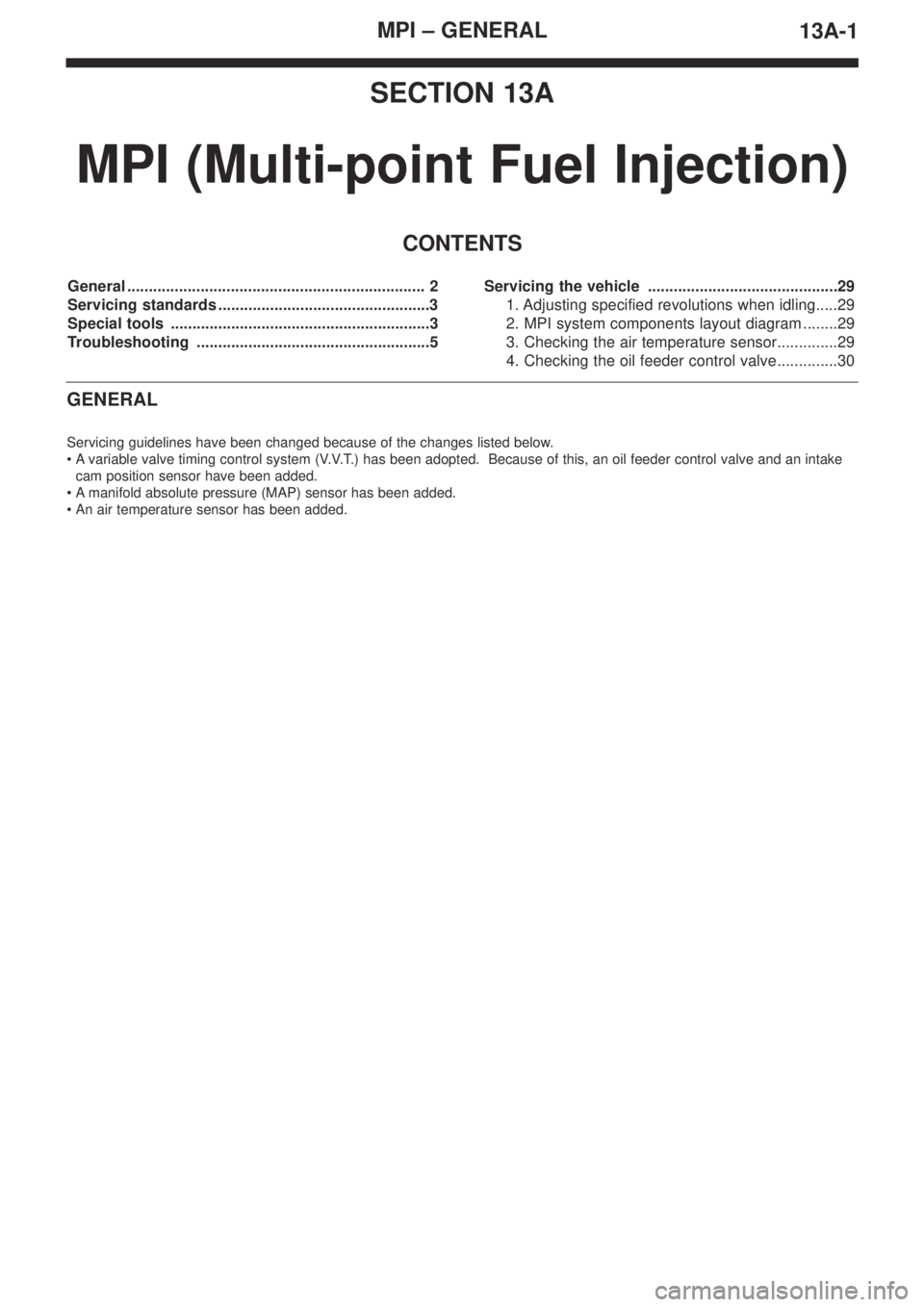
13A-1
SECTION 13A
MPI (Multi-point Fuel Injection)
CONTENTS
General ..................................................................... 2
Servicing standards .................................................3
Special tools ............................................................3
Troubleshooting ......................................................5Servicing the vehicle ............................................29
1. Adjusting specified revolutions when idling.....29
2. MPI system components layout diagram ........29
3. Checking the air temperature sensor..............29
4. Checking the oil feeder control valve..............30
GENERAL
Servicing guidelines have been changed because of the changes listed below.
•Avariable valve timing control system (V.V.T.) has been adopted. Because of this, an oil feeder control valve and an intake
cam position sensor have been added.
•Amanifold absolute pressure (MAP) sensor has been added.
•An air temperature sensor has been added.
Page 42 of 364

MPI – GENERAL13A-2
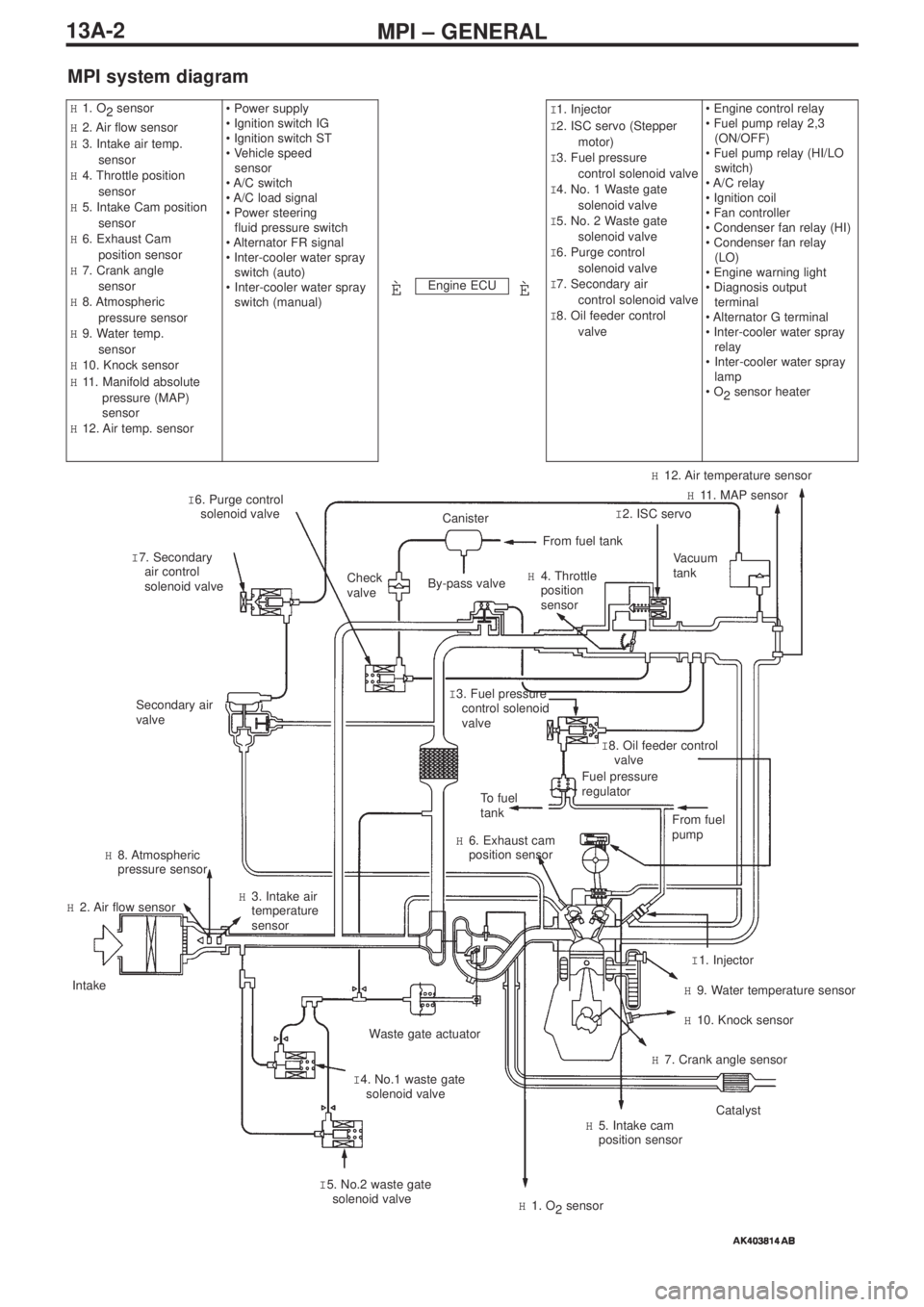
MPI system diagram
Engine ECU
H1. O
2 sensor
H2. Air flow sensor
H3. Intake air temp.
sensor
H4. Throttle position
sensor
H5. Intake Cam position
sensor
H6. Exhaust Cam
position sensor
H7. Crank angle
sensor
H8. Atmospheric
pressure sensor
H9. Water temp.
sensor
H10. Knock sensor
H11. Manifold absolute
pressure (MAP)
sensor
H12. Air temp. sensor• Power supply
• Ignition switch IG
• Ignition switch ST
• Vehicle speed
sensor
• A/C switch
• A/C load signal
• Power steering
fluid pressure switch
• Alternator FR signal
• Inter-cooler water spray
switch (auto)
•Inter-cooler water spray
switch (manual)I1. Injector
I2. ISC servo (Stepper
motor)
I3. Fuel pressure
control solenoid valve
I4. No. 1 Waste gate
solenoid valve
I5. No. 2 Waste gate
solenoid valve
I6. Purge control
solenoid valve
I7. Secondary air
control solenoid valve
I8. Oil feeder control
valve• Engine control relay
• Fuel pump relay 2,3
(ON/OFF)
• Fuel pump relay (HI/LO
switch)
• A/C relay
• Ignition coil
• Fan controller
• Condenser fan relay (HI)
• Condenser fan relay
(LO)
• Engine warning light
• Diagnosis output
terminal
• Alternator G terminal
• Inter-cooler water spray
relay
•Inter-cooler water spray
lamp
• O
2sensor heater
ÈÈ
I 6. Purge control
solenoid valve
I 7. Secondary
air control
solenoid valveCheck
valve
Secondary air
valve
To fuel
tank
H 6. Exhaust cam
position sensor
H 8. Atmospheric
pressure sensor
H 2. Air flow sensor
Intake
Waste gate actuator
I 4. No.1 waste gate
solenoid valve H 3. Intake air
temperature
sensor
I 5. No.2 waste gate
solenoid valve
H 1. O
2sensor
H 5. Intake cam
position sensorCatalyst
H 7. Crank angle sensor
H 10. Knock sensor
H 9. Water temperature sensor
I 1. Injector From fuel
pump
Fuel pressure
regulatorI 8. Oil feeder control
valve I 3. Fuel pressure
control solenoid
valve
Vacuum
tank
I 2. ISC servoH 11. MAP sensor
H 12. Air temperature sensor
H 4. Throttle
position
sensor
From fuel tank
Canister
By-pass valve
Page 45 of 364

MPI – TROUBLESHOOTING
13A-5
TROUBLESHOOTING
1. Diagnosis Functions
1-1 Engine warning light (Check engine lamp)
Changes have been made to engine warning lights.
Checklist for engine warning lights.
1-2 Checking of freeze frame data
Additions have been made to the freeze frame data tables.
Checklist for data tables
1-3 Failsafe and back-up functions
If one of the diagnosis functions detects that one of the main sensors is malfunctioning, it will ensure that the car can be driven
safely, in accordance with the pre-set control logic.
Engine ECU
Air flow sensor (AFS)
Manifold absolute pressure (MAP) sensor system
Intake air temperature sensor
Throttle position sensor (TPS)
Water temperature sensor
Crank angle sensor
Exhaust cam position sensor
Injector
Ignition coil (with built-in power transistor)
Atmospheric pressure sensor
O
2sensor
O
2sensor heater
Fuel system malfunction
Knock sensor
Intake cam position sensor system
Oil feeder control valve system
Item numberType of data Units/condition
95MAP sensorkPa
Malfunctioning itemControl measures taken when a malfunction occurs
Air temperature sensorRegulation of the intake air temperature at 25ºC.
Exhaust cam position sensor(1) Simultaneous flushing out of all fuel pipes.
(But only if the No. 1 cylinder has not been detected in the
TDC position after the ignition switch has been turned "ON".)
(2) Cutting off the fuel 4 seconds after the malfunction has been
detected.
(But only if the No. 1 cylinder has not been detected in the
TDC position after the ignition switch has been turned "ON".)
Intake cam position sensorThe oil feeder control valve should be switched "OFF", and the
angle of the cam should be in the reset position.
Page 156 of 364
LAYOUT DIAGRAMS - ENGINE / TRANSMISSION1-6
B-01 (1-black) Engine oil pressure switch
B-02 Alternator
B-03 (4-grey) Alternator
B-04 Starter
B-05 (1-black) Starter
B-06 (4-black) Throttle position sensorB-07 (2-black) Purge control solenoid valve
B-08 (7-black) Airflow sensor
B-12 (5-grey) Windscreen wiper motor
B-13X Engine speed detection connector
B-14X Starter relay
B-17X Ignition coil relay
ENGINE / TRANSMISSION
Connector Symbol
Control harnessGround cable
Battery
harness
Page 180 of 364
PART INSTALLATION POSITIONS - SOLENOID VALVES2-10
SOLENOID VALVES
Fuel pump relay 1
Intercooler water
spray relay
Fuel pump relay 2Fuel pump relay 1
Blower relay
Power window relay
Oil feeder control
valveFuel pressure
solenoid valve
Purge control
solenoid valve