Page 82 of 364
INTAKE & EXHAUST – EXHAUST MANIFOLD & TURBOCHARGER15-8
Exhaust manifold and turbocharger
Removal and fitting
Jobs to be completed before removal and after
fitting
• Removal and refitting of the valence
• Removal and refitting of the radiator
• Removal and refitting of the air intake hose and
air hose A• Removal and refitting of the cross member bar
• Removal and refitting of the front exhaust pipe
• Draining and refilling of the engine oil
Page 83 of 364

INTAKE & EXHAUST – EXHAUST MANIFOLD15-9
Removal procedure
1. Exhaust manifold heat protector
2. Air pipe ASSY connection
3. O
2sensor
4. Turbocharger heat protector
5. Turbocharger water feed pipe connection
6. Gasket
7. Water hose connection
8. Oil feed pipe
9. Gasket
10. Starter
11.Oil return pipe
12. Oil return pipe gasket (turbocharger side)
13. Oil return pipe gasket (oil pan side)14. Vacuum hose connection
15. Air outlet fitting
16. Air outlet fitting gasket
17. Exhaust fitting bracket
18. Turbocharger and exhaust fitting ASSY
19. Turbocharger ASSY
20. Exhaust fitting gasket
21. Exhaust fitting
22. Turbocharger gasket
23. Turbocharger water return pipe
24. Gasket
25. Exhaust manifold
26. Exhaust manifold gasket
Removal guidelines
� �
A� �
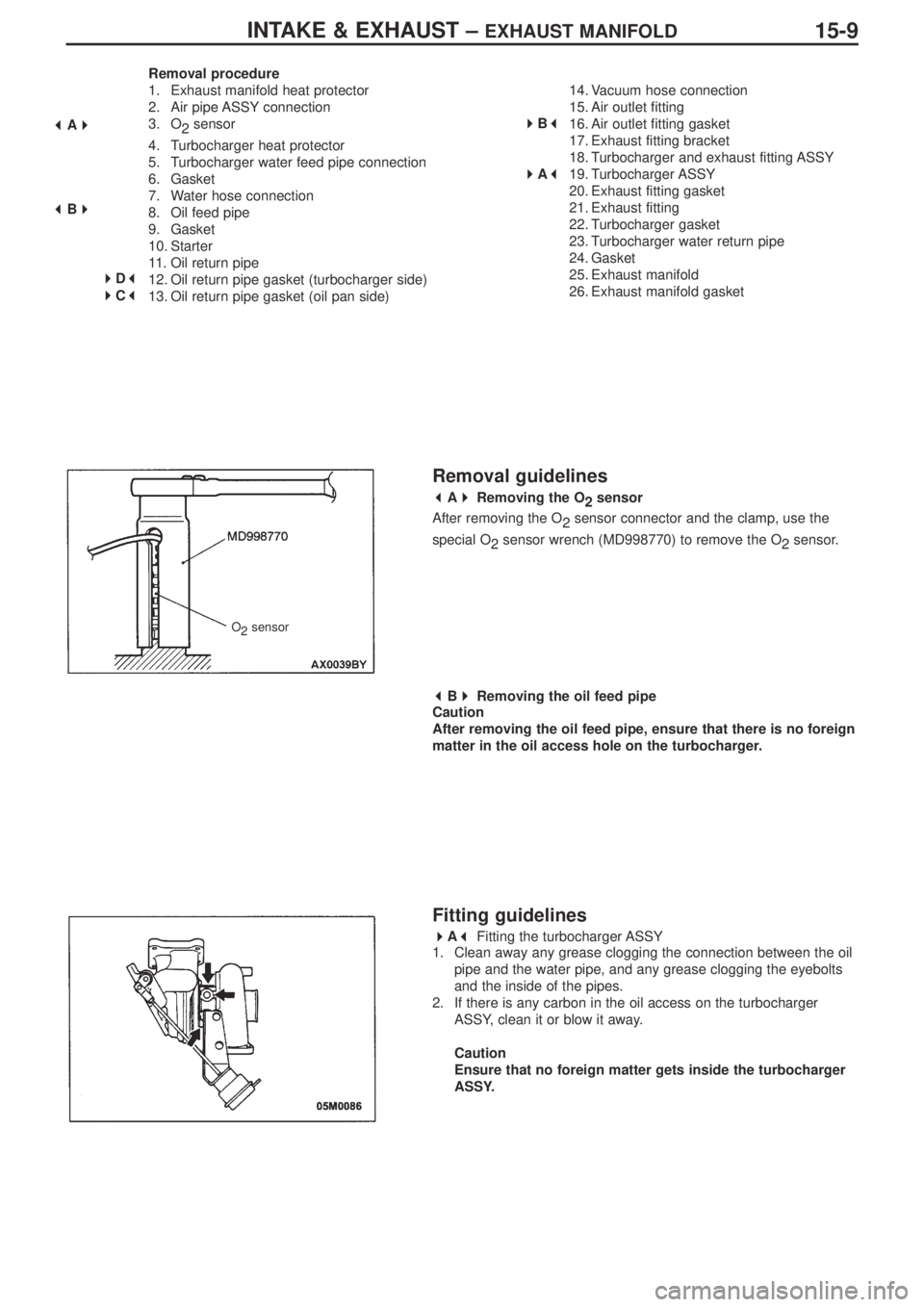
Removing the O
2sensor
After removing the O
2sensor connector and the clamp, use the
special O
2 sensor wrench (MD998770) to remove the O
2sensor.
� �
B� �
Removing the oil feed pipe
Caution
After removing the oil feed pipe, ensure that there is no foreign
matter in the oil access hole on the turbocharger.
Fitting guidelines
� �
A� �
Fitting the turbocharger ASSY
1. Clean away any grease clogging the connection between the oil
pipe and the water pipe, and any grease clogging the eyebolts
and the inside of the pipes.
2. If there is any carbon in the oil access on the turbocharger
ASSY, clean it or blow it away.
Caution
Ensure that no foreign matter gets inside the turbocharger
ASSY.
� �
A� �
� �
B� �
�
�
D� �
� �
C� �
�
�
B� �
� �
A� �
O
2sensor
Page 84 of 364
INTAKE & EXHAUST – EXHAUST MANIFOLD15-10
� �
B� �
Fitting the air outlet fitting gasket
Fit the gasket so that the protruding part is in the position located in
the diagram.
� �
C� �
Fitting the oil return pipe gasket (oil pan side)
Fit so that the printed side of the gasket is on the oil pan side.
� �
D� �
Fitting the oil return pipe gasket (turbocharger side)
Fit so that the printed side of the gasket is on the turbocharger side.turbocharger
protruding part
view “A”
view “A”
print
print
gasket
gasket
3. Apply some fresh engine oil via the fitting hole for the oil feed
pipe in the turbocharger ASSY.
Page 86 of 364
ENGINE ELECTRICAL – CHARGING SYSTEM16-2
Removal procedure
1. Injector connector
2. Accelerator cable connection
3. Delivery pipe, injector, and fuel pressure
regulator ASSY
4. Insulator
5. Insulator
6. Fuel pressure solenoid valve connector
7. Fuel pressure solenoid valve ASSY
8. Knock sensor connector
9. Purge control solenoid valve connector10. Purge control solenoid valve ASSY
11.Oil level gauge and guide ASSY
12. O-ring
13. Drive belt
14. Alternator connector and terminal
• Engine mount
15. Alternator
16. Water pump pulley
17. O
2sensor connector
18. Alternator bracket
(engine oil)
� �
A� ��
�
B� �
� �
C� �
Page 92 of 364

TYRES AND WHEELS – ON-VEHICLE SERVICING31-2
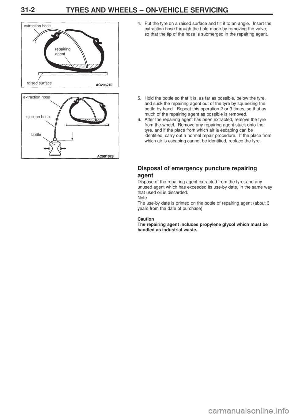
4. Put the tyre on a raised surface and tilt it to an angle. Insert the
extraction hose through the hole made by removing the valve,
so that the tip of the hose is submerged in the repairing agent.
5. Hold the bottle so that it is, as far as possible, below the tyre,
and suck the repairing agent out of the tyre by squeezing the
bottle by hand. Repeat this operation 2 or 3 times, so that as
much of the repairing agent as possible is removed.
6. After the repairing agent has been extracted, remove the tyre
from the wheel. Remove any repairing agent stuck onto the
tyre, and if the place from which air is escaping can be
identified, carry out a normal repair procedure. If the place from
which air is escaping cannot be identified, replace the tyre.
Disposal of emergency puncture repairing
agent
Dispose of the repairing agent extracted from the tyre, and any
unused agent which has exceeded its use-by date, in the same way
that used oil is discarded.
Note
The use-by date is printed on the bottle of repairing agent (about 3
years from the date of purchase)
Caution
The repairing agent includes propylene glycol which must be
handled as industrial waste.
extraction hose
raised surface
repairing
agent
extraction hose
injection hose
bottle
Page 93 of 364

FRONT SUSPENSION – GENERAL, SPECIAL TOOLS, STRUT ASSY
33-1
SECTION 33
FRONT SUSPENSION
CONTENTS
General........................................................1
Special tools ...............................................1Strut ASSY ..................................................1
General
The guidelines for the dismantling and assembly of the front suspension have been changed due to changes made to the
shape of the Bilstein shock absorbers.
Special tools
ToolNumberNameFunction
A: MB991237
B: MB991238A. Spring compressor body
B. Arm setDismantling and assembling
the strut ASSY
MB991680
A: MB991681
B: MB991682Wrench set
A. Wrench
B. Socket
Strut ASSY
Dismantling guidelines
� �
A� �
Removal of the self-locking nut
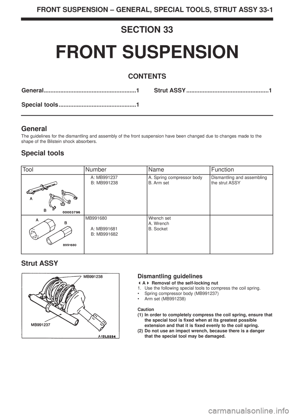
1. Use the following special tools to compress the coil spring.
• Spring compressor body (MB991237)
• Arm set (MB991238)
Caution
(1) In order to completely compress the coil spring, ensure that
the special tool is fixed when at its greatest possible
extension and that it is fixed evenly to the coil spring.
(2) Do not use an impact wrench, because there is a danger
that the special tool may be damaged.
Page 94 of 364

FRONT SUSPENSION – STRUT ASSY33-2
pipe
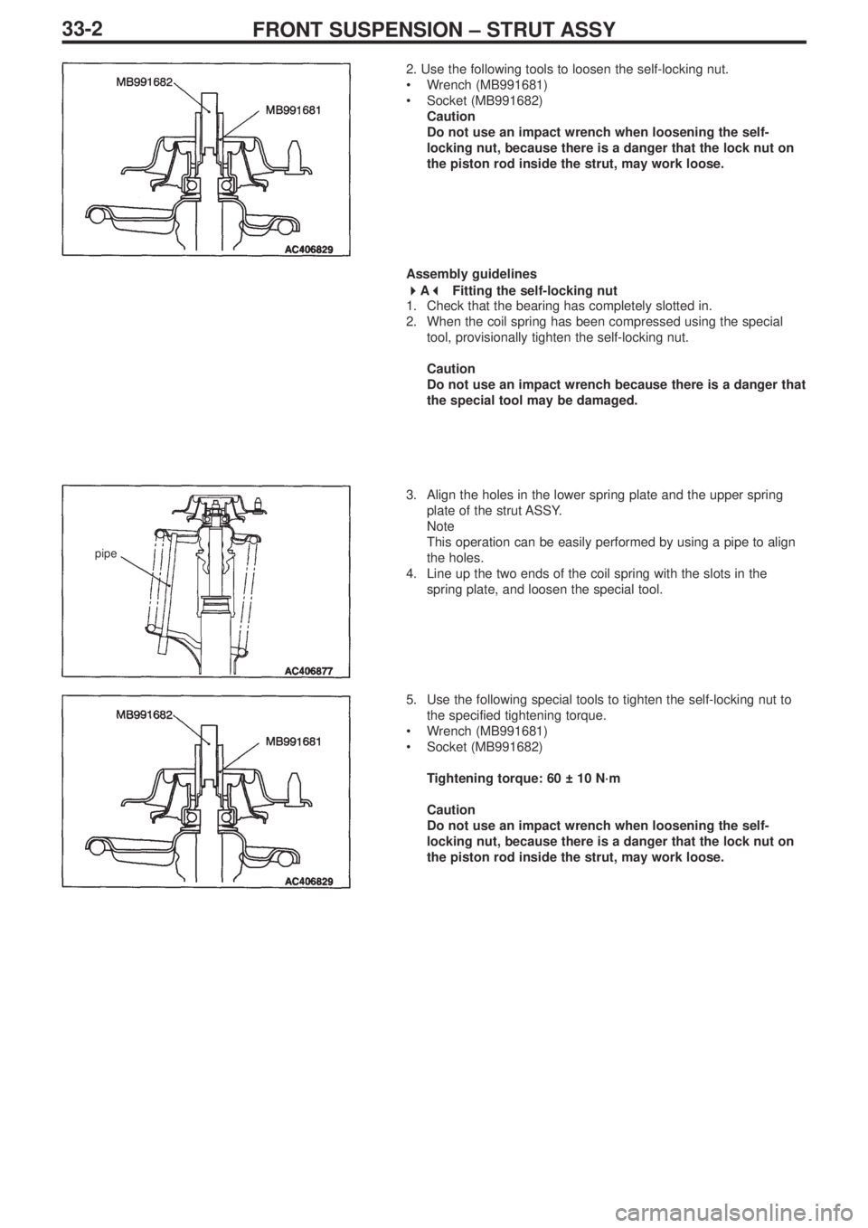
2. Use the following tools to loosen the self-locking nut.
•Wrench (MB991681)
•Socket (MB991682)
Caution
Do not use an impact wrench when loosening the self-
locking nut, because there is a danger that the lock nut on
the piston rod inside the strut, may work loose.
Assembly guidelines
� �
A� �
Fitting the self-locking nut
1. Check that the bearing has completely slotted in.
2. When the coil spring has been compressed using the special
tool, provisionally tighten the self-locking nut.
Caution
Do not use an impact wrench because there is a danger that
the special tool may be damaged.
3. Align the holes in the lower spring plate and the upper spring
plate of the strut ASSY.
Note
This operation can be easily performed by using a pipe to align
the holes.
4. Line up the two ends of the coil spring with the slots in the
spring plate, and loosen the special tool.
5. Use the following special tools to tighten the self-locking nut to
the specified tightening torque.
•Wrench (MB991681)
•Socket (MB991682)
Tightening torque: 60 ± 10 N·m
Caution
Do not use an impact wrench when loosening the self-
locking nut, because there is a danger that the lock nut on
the piston rod inside the strut, may work loose.
Page 99 of 364
EXTERIOR – FRONT BUMPER
51-3
Dismantling and assembly
Dismantling procedure
1. Front 3-diamonds badge
2. Front bumper nut
3. Front number plate garnish
4. Front bumper cover A
5. Front bumper cover B
6. Air dam skirt panel
7. Front bumper centre net
8. Front bumper lower plate
9. Front bumper upper plate
10. Front bumper upper support11.Air intake cover
12. Front bumper net
13. Bumper side net (LH)
14. Oil cooler duct
15. Bumper side net (RH)
•Inter-cooler water spray hose and nozzle
(Ref Section 15)
16. Front bumper side plate
17. Front bumper upper reinforcement
18. Front bumper facing
Note:
The main points for dismantling and assembly remain unchanged.
Cross section through A-A
hook
Cross section through B-B
clip
� �
A� �
�
�
A� �