Page 57 of 364

13A-17MPI – TROUBLESHOOTING
*: Refer to the 01-1 Service Manual for the Lancer Evolution VIII (No.1036K02)
*: Refer to the 03-1 Service Manual for the Lancer Evolution VIII (No.1036K07)
Repair
Repair
Repair
Repair
Repair
Repair
Continued from previous page
Replace the spark plug wire
Replace the spark plug
Replace the ignition coil
Inspection procedure 33: Inspection of the No.1 waste
gate solenoid valve (Ref: P13A-78) *2
Inspection procedure 37: Inspection of the No.2 waste
gate solenoid valve (Ref: P13A-21)
Inspection procedure 31: Inspection of the fuel control
solenoid valve (Ref: P13A-76) *2
Inspection procedure 38: Inspection of the air
temperature sensor (Ref: P13A-22)
Check the spark plug wire (Ref: Section 16: Ignition
apparatus)
Check the spark plug (Ref: Section 16: Ignition
apparatus)
Check connectors B-123 & B-119
Check the ignition coil (Ref: Section 16: Ignition
Apparatus)
Inspect the harness and the connectors between each
cylinder’s ignition coil and the body earth, and between
the engine ECU and the ignition coil. Check for cut or
short circuited wires, or other damage.
MUT-II/III Actuator test
•No.12: Waste gate solenoid valve (Ref: P13A-87)*2
Check the supercharge pressure of the turbo charger
(Ref: Section 15: Intake/Exhaust car servicing)
Check the supercharge pressure control system (Ref:
Section 15: Intake/Exhaust car servicing)
MUT-II/III Actuator test
•No.09: Fuel pressure control solenoid valve (Ref:
P13A-87)
Check the fuel pressure (Ref: P13D-109)
Check the compression pressure (Ref: Section 11:
Engine tuning)
If the intake hose and the inlet manifold are damaged
check the air intake and repair as necessary.
Measurements taken at B-108 air temperature sensor
connector
•Using the test harness (MB991658), connect it to only
connectors No.1 and No.2 and measure at the pick-
up harness component.
•Ignition switch: ON
•Voltage across earth at 1
OK:surrounding temperature -20ºC 3.8~4.4V
surrounding temperature 0ºC 3.2~3.8V
surrounding temperature 20ºC 2.3~2.9V
surrounding temperature 40ºC 1.5~2.1V
surrounding temperature 60ºC 0.8~1.4V
surrounding temperature 80ºC 0.4~1.0V
OK
OK
OK
OK
OK
OK
OK
OK
OK
OK
OK
OK
OK
NG
NG
NG
NG
NG
NG
NG
NG
NG
NG
NG
Page 69 of 364

13A-29MPI – TROUBLESHOOTING, ON-VEHICLE SERVICING
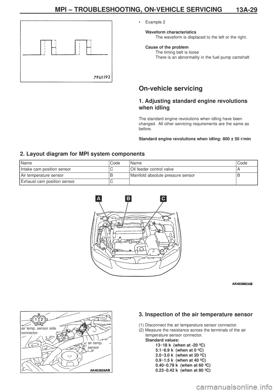
•Example 2
Waveform characteristics
The waveform is displaced to the left or the right.
Cause of the problem
The timing belt is loose
There is an abnormality in the fuel pump camshaft
On-vehicle servicing
1. Adjusting standard engine revolutions
when idling
The standard engine revolutions when idling have been
changed. All other servicing requirements are the same as
before.
Standard engine revolutions when idling: 800 ± 50 r/min
NameCodeNameCode
Intake cam position sensorCOil feeder control valveA
Air temperature sensorBManifold absolute pressure sensorB
Exhaust cam position sensorC
2. Layout diagram for MPI system components
air temp. sensor side
connector
air temp.
sensor
3. Inspection of the air temperature sensor
(1) Disconnect the air temperature sensor connector.
(2) Measure the resistance across the terminals of the air
temperature sensor connector.
Standard values:
13~18 kΩ (when at -20 ºC)
5.1~6.9 kΩ (when at 0 ºC)
2.0~3.0 kΩ (when at 20 ºC)
0.9~1.5 kΩ (when at 40 ºC)
0.40~0.78 kΩ (when at 60 ºC)
0.23~0.42 kΩ (when at 80 ºC)
Page 70 of 364

MPI – ON-VEHICLE SERVICING13A-30
(3) Remove the air temperature sensor
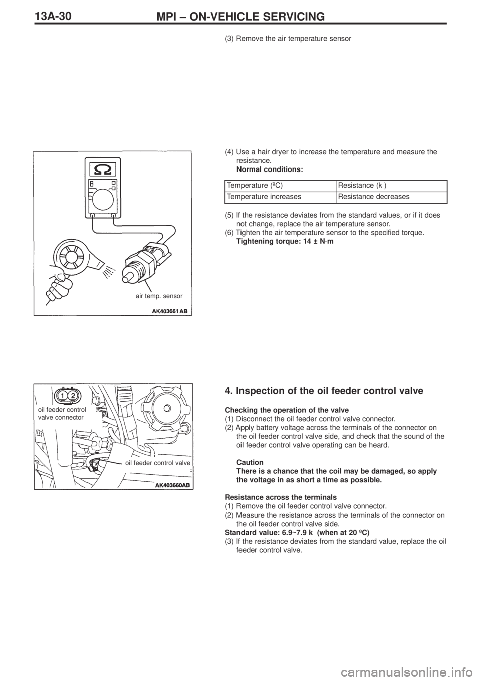
(4) Use a hair dryer to increase the temperature and measure the
resistance.
Normal conditions:
air temp. sensor
Temperature (ºC)Resistance (kΩ)
Temperature increasesResistance decreases
(5) If the resistance deviates from the standard values, or if it does
not change, replace the air temperature sensor.
(6) Tighten the air temperature sensor to the specified torque.
Tightening torque: 14 ± N·m
4. Inspection of the oil feeder control valve
Checking the operation of the valve
(1) Disconnect the oil feeder control valve connector.
(2) Apply battery voltage across the terminals of the connector on
the oil feeder control valve side, and check that the sound of the
oil feeder control valve operating can be heard.
Caution
There is a chance that the coil may be damaged, so apply
the voltage in as short a time as possible.
Resistance across the terminals
(1) Remove the oil feeder control valve connector.
(2) Measure the resistance across the terminals of the connector on
the oil feeder control valve side.
Standard value: 6.9~7.9 kΩ (when at 20 ºC)
(3) If the resistance deviates from the standard value, replace the oil
feeder control valve.oil feeder control
valve connector
oil feeder control valve
Page 72 of 364
ENGINE COOLING – WATER PUMP14-2
Water pump
Removal and fitting
Jobs to be completed before removal and after fitting
•Draining and refilling of the coolant
•Removal and refitting of the timing belt (Ref Section 11)
Removal procedure
1. Alternator bracket
2. Water pump
3. Water pump gasket
4. O-ring
Fitting guidelines
� �
A� �
Fitting the O-ring
Fit the O-ring into the O-ring groove at the end of the water inlet
pipe, and insert it into the water pump after moistening with water
the places where the O-ring will make contact with the water pump.
Caution
Ensure that absolutely no engine oil, or other type of grease,
gets onto the O-ring.
Positions for fitting different sized bolts
Nominal diameter and nominal length (mm)
� �
A� �
water pump
O-ring
water inlet pipe
Page 74 of 364

ENGINE COOLING – WATER HOSE AND PIPE14-4
Removal guidelines
� �
A� �
Removing the radiator upper hose and the radiator
lower hose
Mark the radiator hose and the hose clamp with indicator marks
and then remove the radiator hose.
Fitting guidelines
� �
A� �
Fitting the O-ring and the water inlet pipe
Fit the O-ring into the groove at the end of the water inlet pipe, and
insert it after moistening with water the places where the O-ring and
the water inlet pipe will be in contact.
Caution
Ensure that absolutely no engine oil, or other type of grease,
gets onto the O-ring.
� �
B� �
Connecting the radiator lower hose and the radiator
upper hose
1. Insert the hose as far as the protrusion on the water inlet pipe
and the water outlet fitting.
2. Match up the indicator marks on the radiator hose and the hose
clamp, and fit the radiator hose.
indicator marks
water pump and
thermostat case
O-ring
water inlet pipe
protrusion
water inlet pipe and
water outlet pipe fittingindicator marks
Page 79 of 364
INTAKE & EXHAUST – SECONDARY AIR CONTROL SYSTEM, INLET MANIFOLD15-5
Fitting guidelines
� �
A� �
Fitting the gasket
Fit the gasket so that the protruding part points in the direction
shown in the diagram.
Inlet manifold
Removal and fitting
Jobs to be completed before removal and
after fitting
•Take measures to prevent fuel leaking (only
before removal)
•Removal and refitting of the valence (Ref
Section 15: Front bumper)
•Draining and refilling the coolant
•Removal and refitting of the air duct•Removal and refitting of the strut tower bar
•Removal and refitting of the throttle body
•Removal and refitting of the secondary air
control valve (Ref P15-4)
•Removal and refitting of the cross member bar
•Removal and refitting of the front exhaust pipe
protruding
part
(engine oil)
(engine oil)
Page 80 of 364
INTAKE & EXHAUST – INLET MANIFOLD15-6
Removal procedure
1. Centre cover
2. Ignition coil connector
3. O
2sensor connector
4. Oil feeder control valve connector
5. Crank angle sensor connector
6. Injector connector
7. Air temperature sensor connector
8. Manifold absolute pressure sensor
connector
9. Purge control solenoid valve connector
10. Knock sensor connector
11.Fuel pressure solenoid valve connector12. Vacuum hose connection
13. Vacuum hose connection
14. Fuel return hose connection
15. Fuel high pressure hose connection
16. O-ring
17. Delivery pipe, injector and fuel pressure
regulator ASSY
18. Insulator
19. Insulator
20. Oil level gauge & guide ASSY
21. O-ring
22. Brake booster vacuum hose connection
23. Purge hose connection
� �
A� �
� �
A� �
�
�
A� �
Page 81 of 364

INTAKE & EXHAUST – INLET MANIFOLD
15-7
Removal procedure
24. Knock sensor connector
25. Purge control solenoid valve ASSY
26. Vacuum hose
27. Fuel pressure solenoid valve ASSY
28. PCV hose
•Alternator (Ref Section 16: Alternator)
29. Secondary air control solenoid valve
connector
30. Vacuum tank, ACV solenoid valve,
vacuum hose & pipe ASSY31. Inlet manifold stay
32. Cover
33. Gasket
34. Harness connection
35. Crank angle sensor connector
36. Alternator bracket
37. Inlet manifold
38. Inlet manifold gasket
Removal guidelines
� �
A� �
Removal of the delivery pipe, the injector and the fuel
pressure regulator ASSY
Remove the deliver pipe, with the injector and the fuel pressure
regulator intact.
Caution
When removing the delivery pipe, be careful not to drop the
injector.
Fitting guidelines
� �
A� �
Connecting the O-ring and the fuel high pressure hose
1. Apply a small quantity of fresh engine oil to the O-ring, and
insert it into the delivery pipe without damaging the O-ring.
2. Check that the high pressure hose can be turned smoothly. If it
cannot be turned smoothly there is a possibility that it is biting
into the O-ring, so remove the high pressure hose and check for
any damage to the O-ring. If the O-ring is undamaged, reinsert it
into the delivery pipe and check once more whether the hose
can be turned smoothly.
3. Tighten the mounting bolt to the specified torque.
Tightening torque: 5.0 ± 1.0 N·m