Page 112 of 364

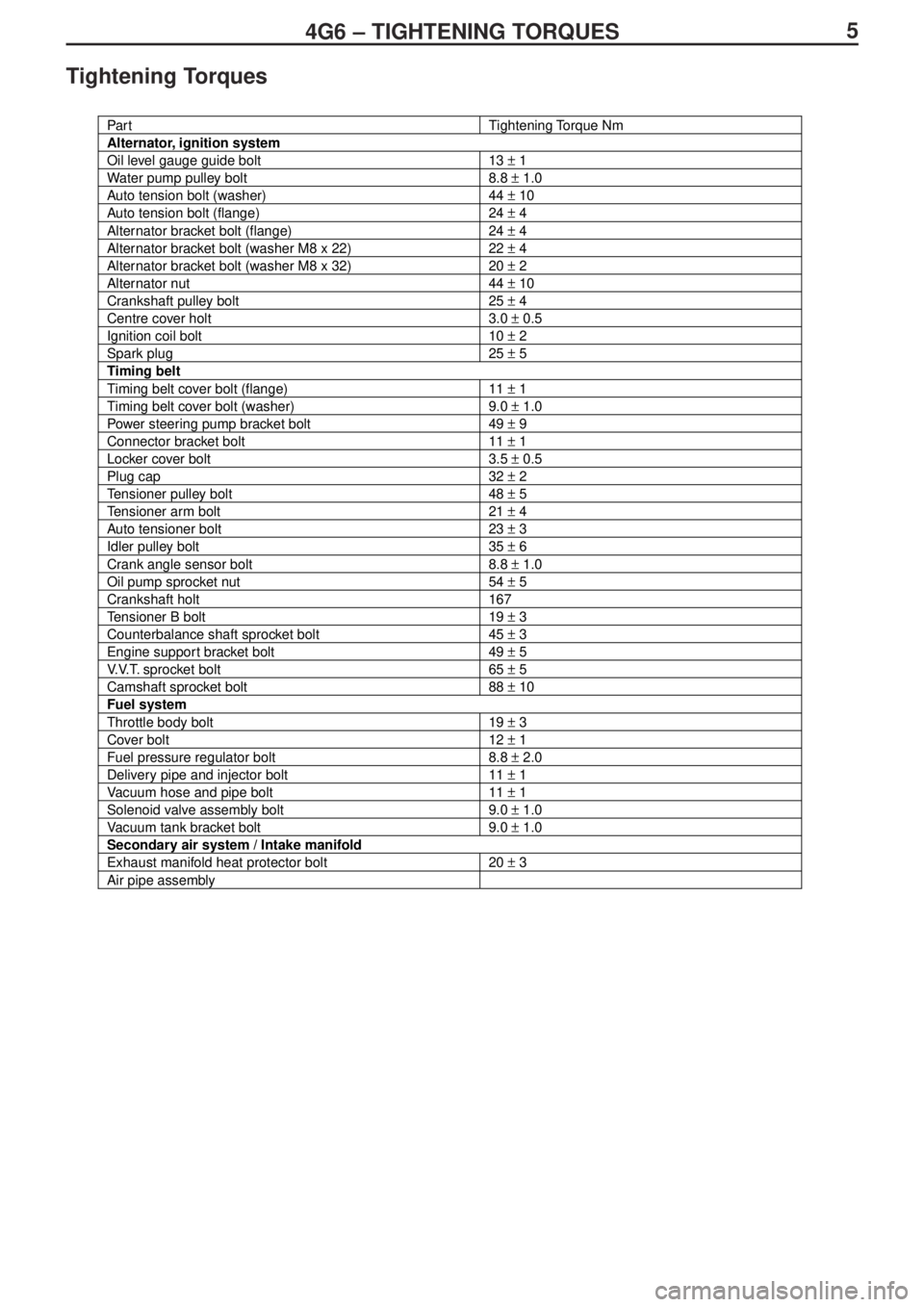
54G6 – TIGHTENING TORQUES
Tightening Torques
Par tTightening Torque Nm
Alternator, ignition system
Oil level gauge guide bolt13 ± 1
Water pump pulley bolt8.8 ± 1.0
Auto tension bolt (washer)44 ± 10
Auto tension bolt (flange)24 ± 4
Alternator bracket bolt (flange)24 ± 4
Alternator bracket bolt (washer M8 x 22)22 ± 4
Alternator bracket bolt (washer M8 x 32)20 ± 2
Alternator nut44 ± 10
Crankshaft pulley bolt25 ± 4
Centre cover holt3.0 ± 0.5
Ignition coil bolt10 ± 2
Spark plug25 ± 5
Timing belt
Timing belt cover bolt (flange)11 ± 1
Timing belt cover bolt (washer)9.0 ± 1.0
Power steering pump bracket bolt49 ± 9
Connector bracket bolt11 ± 1
Locker cover bolt3.5 ± 0.5
Plug cap32 ± 2
Tensioner pulley bolt48 ± 5
Tensioner arm bolt21 ± 4
Auto tensioner bolt23 ± 3
Idler pulley bolt35 ± 6
Crank angle sensor bolt8.8 ± 1.0
Oil pump sprocket nut54 ± 5
Crankshaft holt167
Tensioner B bolt19 ± 3
Counterbalance shaft sprocket bolt45 ± 3
Engine support bracket bolt49 ± 5
V.V.T. sprocket bolt65 ± 5
Camshaft sprocket bolt88 ± 10
Fuel system
Throttle body bolt19 ± 3
Cover bolt12 ± 1
Fuel pressure regulator bolt8.8 ± 2.0
Delivery pipe and injector bolt11 ± 1
Vacuum hose and pipe bolt11 ± 1
Solenoid valve assembly bolt9.0 ± 1.0
Vacuum tank bracket bolt9.0 ± 1.0
Secondary air system / Intake manifold
Exhaust manifold heat protector bolt20 ± 3
Air pipe assembly
Page 120 of 364
134G6 – FUEL SYSTEM
Fuel System
Removal and Installation
Removal Sequence
1. Throttle body assembly
2. Throttle body gasket
3. Cover
4. Gasket
5. Fuel hose
6. Fuel pressure regulator
7. O ring
8. Delivery pipe and injector
9. Insulator
10. Fuel return pipe
11.Insulator
12. Injector
13. O ring14. Grommet
15. Delivery pipe
16. Vacuum hose
17. Vacuum hose
18. Vacuum hose
19. Solenoid valve assembly
20. Solenoid valve assembly
21. Vacuum hose and pipe
22. Solenoid valve assembly
23. Vacuum tank bracket
24. Vacuum tank
25. Vacuum hose assembly
26. Vacuum hose and pipe
�
* 1�*
�
* 1�*
�
* 1�*
�A�*
Page 121 of 364
144G6 – FUEL SYSTEM
Installation Service Point
Installation of cover
The side of the cover marked “gasket side” should be assembled
facing the inlet manifold.
� A�Gasket
sideCover
Gasket
Inlet manifold
Page 153 of 364
LAYOUT DIAGRAMS - GENERAL LAYOUT DIAGRAM1-3
Front
harness (RH)Control panelInstrument
panel harnessRoof harness
Floor harness (RH)
Battery
harness
Front harness (LH)
Front door
harness *Floor
harness (LH)Fuel harnessRear door harness *
Note :
1. This diagram shows the main wiring harnesses only.
2. The * symbol indicates that the harness is also fitted on the right-hand side.
General Layout Diagram
Page 158 of 364
LAYOUT DIAGRAMS - ENGINE / TRANSMISSION1-8
B-106 (2-grey) Knock sensor
B-108 (2-black) Coolant temperature sensor
B-109 (34-black) ABS-ECU
B-114 (1-black) Water temperature gauge unit
B-115 (3-black) Exhaust cam position sensorB-119 (3-grey) Ignition coil 2
B-122 (3-black) Crank angle sensor
B-123 (3-grey) Ignition coil 1
B-124 (2-black) Fuel pressure solenoid valve
Engine / Transmission (continued)
Connector Symbol
Control harness
Battery harness
Page 159 of 364
LAYOUT DIAGRAMS - ENGINE / TRANSMISSION1-9
B-126 (6-black) Idle speed control servo
B-127 (4) Electric pump relay
B-128 (4) Fuel pump relay 3
B-129 (6-black) Register (for injector)
B-130 (2-black) Fuel pump register
B-131 (3-black) Vehicle speed sensorB-132 (2-black) Back-up lamp switch
B-133 (2-black) Secondary air control solenoid valve
B-134 (2-black) Oil feeder control valve
B-135 (3-black) Manifold absolute pressure sensor
Ground cable
Transmission harness
Page 165 of 364
LAYOUT DIAGRAMS - INSTRUMENT PANEL1-15
C-214 (5) Blower relay
C-215 (15) Floor harness (RH) / J/B junction
C-216 (3) Roof harness / J/B junction
C-217 (4) Dummy connector
C-218 (4) Dummy connector
C-219 (4) Fuel pump relay 2
C-220 (4) Intercooler water spray relay
C-221 (4) Fuel pump relay 1C-222 (5) Power window relay
C-223 (2) Instrument panel harness / J/B junction
C-224 (20) ETACS-ECU
C-225 (24-grey) ETACS-ECU
C-226 (24) ETACS-ECU
C-228 (5) Steer sensor
(Front side)
Instrument panel harness
Dedicated fuse
Floor harness (RH)
Roof harness(Rear side)
Page 166 of 364
LAYOUT DIAGRAMS - FLOOR / ROOF1-16
D-01 (3) Door switch (front : RH)
D-02 (2-black) Seatbelt pre-tensioner (RH)
D-03 (8) Floor harness (RH) / Rear door harness
(RH) junction
D-04 (2) Front cabin lamp
D-05 (2-black) Rear ABS sensor (RH)
D-06 (2-grey) Rear cabin lamp (Vehicle not fitted with
sunroof)
D-07 (3) Door switch (rear : RH)
D-09 (3) Door switch (rear : LH)D-10 (5-grey) Fuel pump and fuel gauge unit (main)
D-11 (2-black) Rear ABS sensor (LH)
D-12 (8) Floor harness (RH) / Fuel harness
junction
D-13 (8) Floor harness (LH) / Rear door harness
(LH) junction
D-14 (2-black) Seatbelt pre-tensioner (LH)
D-15 (3) Door switch (front : LH)
FLOOR / ROOF
Connector Symbol
Roof harness
Floor
harness (RH)
Instrument panel harness
Console harness