Page 79 of 364
INTAKE & EXHAUST – SECONDARY AIR CONTROL SYSTEM, INLET MANIFOLD15-5
Fitting guidelines
� �
A� �
Fitting the gasket
Fit the gasket so that the protruding part points in the direction
shown in the diagram.
Inlet manifold
Removal and fitting
Jobs to be completed before removal and
after fitting
•Take measures to prevent fuel leaking (only
before removal)
•Removal and refitting of the valence (Ref
Section 15: Front bumper)
•Draining and refilling the coolant
•Removal and refitting of the air duct•Removal and refitting of the strut tower bar
•Removal and refitting of the throttle body
•Removal and refitting of the secondary air
control valve (Ref P15-4)
•Removal and refitting of the cross member bar
•Removal and refitting of the front exhaust pipe
protruding
part
(engine oil)
(engine oil)
Page 80 of 364
INTAKE & EXHAUST – INLET MANIFOLD15-6
Removal procedure
1. Centre cover
2. Ignition coil connector
3. O
2sensor connector
4. Oil feeder control valve connector
5. Crank angle sensor connector
6. Injector connector
7. Air temperature sensor connector
8. Manifold absolute pressure sensor
connector
9. Purge control solenoid valve connector
10. Knock sensor connector
11.Fuel pressure solenoid valve connector12. Vacuum hose connection
13. Vacuum hose connection
14. Fuel return hose connection
15. Fuel high pressure hose connection
16. O-ring
17. Delivery pipe, injector and fuel pressure
regulator ASSY
18. Insulator
19. Insulator
20. Oil level gauge & guide ASSY
21. O-ring
22. Brake booster vacuum hose connection
23. Purge hose connection
� �
A� �
� �
A� �
�
�
A� �
Page 81 of 364

INTAKE & EXHAUST – INLET MANIFOLD
15-7
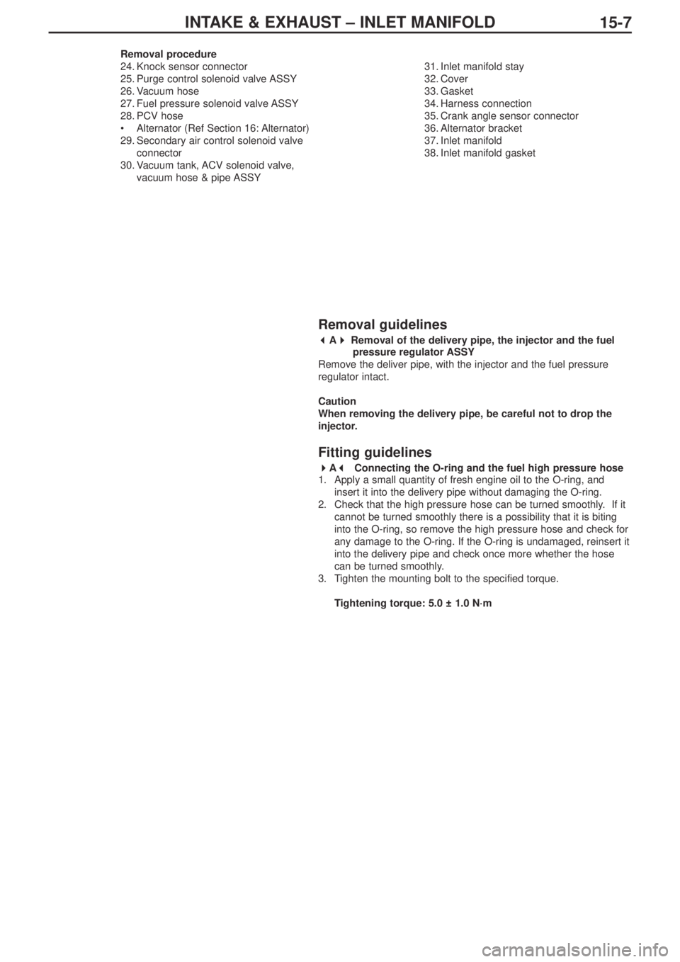
Removal procedure
24. Knock sensor connector
25. Purge control solenoid valve ASSY
26. Vacuum hose
27. Fuel pressure solenoid valve ASSY
28. PCV hose
•Alternator (Ref Section 16: Alternator)
29. Secondary air control solenoid valve
connector
30. Vacuum tank, ACV solenoid valve,
vacuum hose & pipe ASSY31. Inlet manifold stay
32. Cover
33. Gasket
34. Harness connection
35. Crank angle sensor connector
36. Alternator bracket
37. Inlet manifold
38. Inlet manifold gasket
Removal guidelines
� �
A� �
Removal of the delivery pipe, the injector and the fuel
pressure regulator ASSY
Remove the deliver pipe, with the injector and the fuel pressure
regulator intact.
Caution
When removing the delivery pipe, be careful not to drop the
injector.
Fitting guidelines
� �
A� �
Connecting the O-ring and the fuel high pressure hose
1. Apply a small quantity of fresh engine oil to the O-ring, and
insert it into the delivery pipe without damaging the O-ring.
2. Check that the high pressure hose can be turned smoothly. If it
cannot be turned smoothly there is a possibility that it is biting
into the O-ring, so remove the high pressure hose and check for
any damage to the O-ring. If the O-ring is undamaged, reinsert it
into the delivery pipe and check once more whether the hose
can be turned smoothly.
3. Tighten the mounting bolt to the specified torque.
Tightening torque: 5.0 ± 1.0 N·m
Page 86 of 364
ENGINE ELECTRICAL – CHARGING SYSTEM16-2
Removal procedure
1. Injector connector
2. Accelerator cable connection
3. Delivery pipe, injector, and fuel pressure
regulator ASSY
4. Insulator
5. Insulator
6. Fuel pressure solenoid valve connector
7. Fuel pressure solenoid valve ASSY
8. Knock sensor connector
9. Purge control solenoid valve connector10. Purge control solenoid valve ASSY
11.Oil level gauge and guide ASSY
12. O-ring
13. Drive belt
14. Alternator connector and terminal
• Engine mount
15. Alternator
16. Water pump pulley
17. O
2sensor connector
18. Alternator bracket
(engine oil)
� �
A� ��
�
B� �
� �
C� �
Page 87 of 364

ENGINE ELECTRICAL – CHARGING SYSTEM
16-3
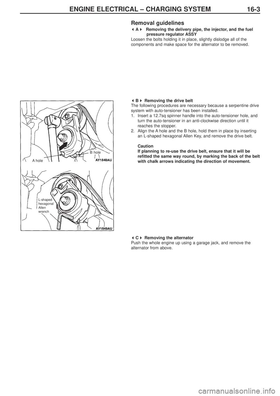
Removal guidelines
� �
A� �
Removing the delivery pipe, the injector, and the fuel
pressure regulator ASSY
Loosen the bolts holding it in place, slightly dislodge all of the
components and make space for the alternator to be removed.
� �
B� �
Removing the drive belt
The following procedures are necessary because a serpentine drive
system with auto-tensioner has been installed.
1. Insert a 12.7sq spinner handle into the auto-tensioner hole, and
turn the auto-tensioner in an anti-clockwise direction until it
reaches the stopper.
2. Align the A hole and the B hole, hold them in place by inserting
an L-shaped hexagonal Allen Key, and remove the drive belt.
Caution
If planning to re-use the drive belt, ensure that it will be
refitted the same way round, by marking the back of the belt
with chalk arrows indicating the direction of movement.
� �
C� �
Removing the alternator
Push the whole engine up using a garage jack, and remove the
alternator from above.
AholeB hole
L-shaped
hexagonal
Allen
wrench
Page 89 of 364
REAR AXLE – GENERAL, DIFFERENTIAL CARRIER 27B-1
SECTION 27B
REAR AXLE
CONTENTS
General........................................................1 Differential carrier
AYC system> ..............................................1
General
The tightening torque for the flare nut which joins the fuel pressure unit hose ASSY and the differential carrier ASSY, has been
changed. Other servicing guidelines remain unchanged.
Differential carrier
Removal and fitting
Note
*1: When the screw is dry.
*2: When the screw is lubricated.
NEWOLDfuel pressure unit hose ASSY
differential carrier ASSY
Page 108 of 364

Service Manual
4G6
FOREWORD
This manual contains information about the 4G6
DOHC engine. It only covers those points that are
different from the service manuals listed below.
Therefore, this manual should be used in conjunction
with the following manuals.
• 4G6 DOHC engine Service Manual (No. 1039G46)
• 4G6 DOHC engine Service Manual Supplement
(No.1039G63)
This manual is based on the engine specifications as of
March 2005. Please note that some engine details may
not match those given in this manual due to
subsequent changes in engine specifications. The units
shown in this manual are the standard international
SI units.
(However, conventional units are used for some figures
taken from existing documents)
If you have any opinions, requests or queries regarding
this manual, please write them down on the “Servicing
Comment Form” on the last page, and fax them to us.
March 2005
Mitsubishi Motor Corporation
This manual is printed on recycled paper.
CONTENTS
General Information . . . . . . . . . . . . . . . 4
Servicing Specification Values . . . . . . 4
Tightening torques . . . . . . . . . . . . . . . . 5
Sealants . . . . . . . . . . . . . . . . . . . . . . . . . 7
Alternator / Ignition system . . . . . . . . . 8
Timing belt . . . . . . . . . . . . . . . . . . . . . 10
Fuel system . . . . . . . . . . . . . . . . . . . . . 13
Secondary air system /
inlet manifold . . . . . . . . . . . . . . . . . . . 15
Exhaust manifold . . . . . . . . . . . . . . . . 16
Water pump / Water hose . . . . . . . . . 17
Rocker arm / Cam shaft . . . . . . . . . . . 18
Oil pump / Sump . . . . . . . . . . . . . . . . . 21
Pistons / Connecting rods . . . . . . . . . 22
Crank shaft / Cylinder block . . . . . . . 25
Turbocharger. . . . . . . . . . . . . . . . . . . . 27
DOHC
ENGINE
Page 111 of 364

44G6 – GENERAL INFORMATION/ SERVICING SPECIFICATIONS
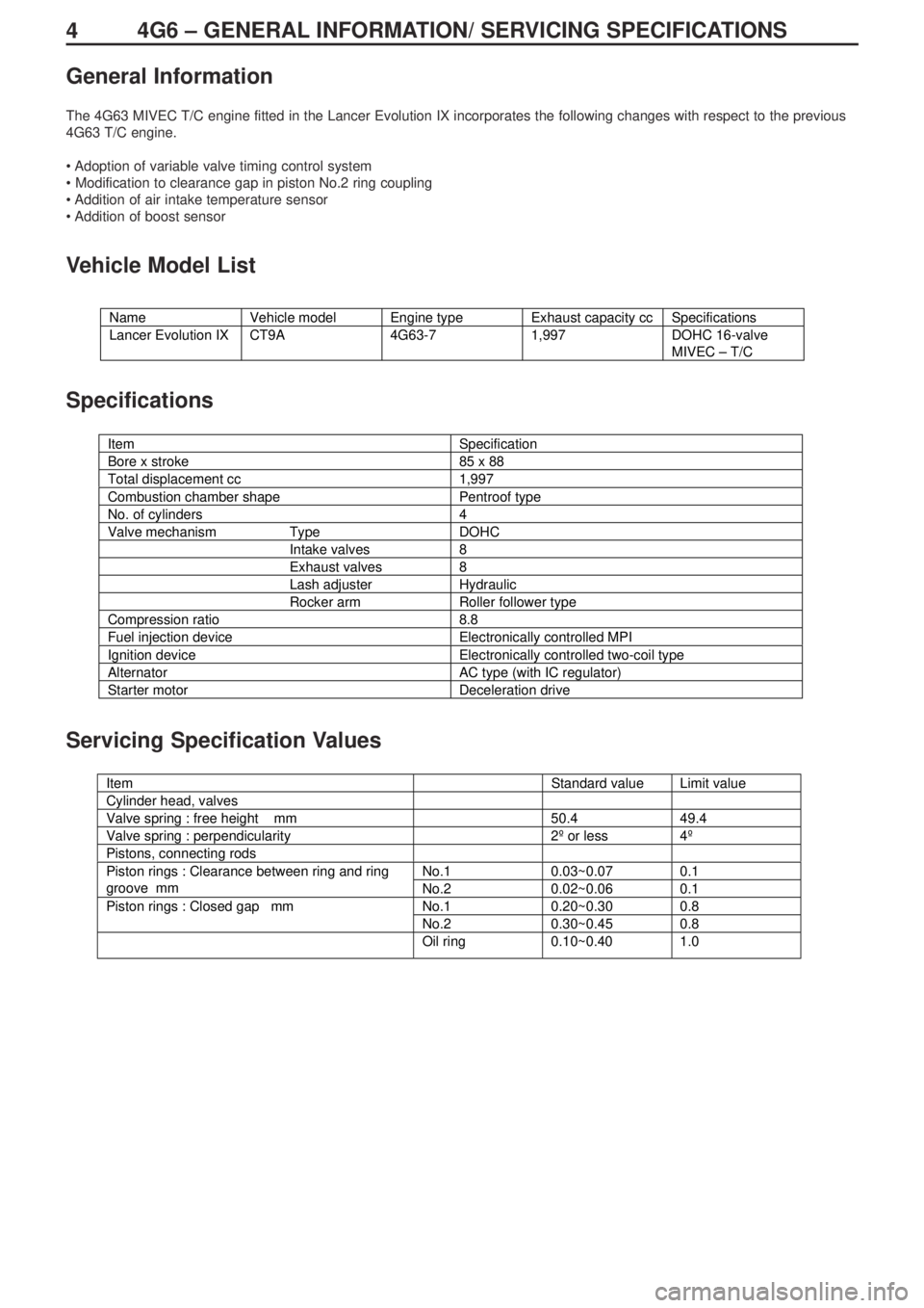
General Information
The 4G63 MIVEC T/C engine fitted in the Lancer Evolution IX incorporates the following changes with respect to the previous
4G63 T/C engine.
• Adoption of variable valve timing control system
• Modification to clearance gap in piston No.2 ring coupling
• Addition of air intake temperature sensor
• Addition of boost sensor
Vehicle Model List
Specifications
Servicing Specification Values
Name Vehicle model Engine type Exhaust capacity cc Specifications
Lancer Evolution IX CT9A 4G63-7 1,997 DOHC 16-valve
MIVEC – T/C
Item Specification
Bore x stroke 85 x 88
Total displacement cc 1,997
Combustion chamber shape Pentroof type
No. of cylinders 4
Valve mechanism Type DOHC
Intake valves 8
Exhaust valves 8
Lash adjuster Hydraulic
Rocker arm Roller follower type
Compression ratio 8.8
Fuel injection device Electronically controlled MPI
Ignition device Electronically controlled two-coil type
Alternator AC type (with IC regulator)
Starter motor Deceleration drive
g
Item Standard value Limit value
Cylinder head, valves
Valve spring : free height mm 50.4 49.4
Valve spring : perpendicularity 2º or less 4º
Pistons, connecting rods
No.1 0.03~0.07 0.1Piston rings : Clearance between ring and ring
groove mm
No.2 0.02~0.06 0.1
No.1 0.20~0.30 0.8Piston rings : Closed gap mm
No.2 0.30~0.45 0.8
Oil ring 0.10~0.40 1.0