Page 94 of 364
FRONT SUSPENSION – STRUT ASSY33-2
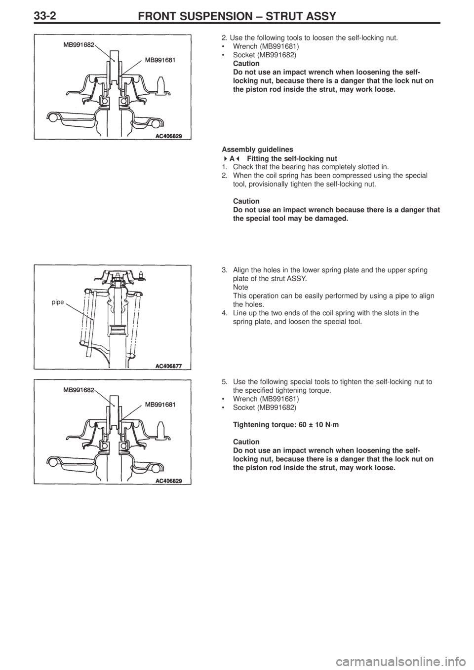
pipe
2. Use the following tools to loosen the self-locking nut.
•Wrench (MB991681)
•Socket (MB991682)
Caution
Do not use an impact wrench when loosening the self-
locking nut, because there is a danger that the lock nut on
the piston rod inside the strut, may work loose.
Assembly guidelines
� �
A� �
Fitting the self-locking nut
1. Check that the bearing has completely slotted in.
2. When the coil spring has been compressed using the special
tool, provisionally tighten the self-locking nut.
Caution
Do not use an impact wrench because there is a danger that
the special tool may be damaged.
3. Align the holes in the lower spring plate and the upper spring
plate of the strut ASSY.
Note
This operation can be easily performed by using a pipe to align
the holes.
4. Line up the two ends of the coil spring with the slots in the
spring plate, and loosen the special tool.
5. Use the following special tools to tighten the self-locking nut to
the specified tightening torque.
•Wrench (MB991681)
•Socket (MB991682)
Tightening torque: 60 ± 10 N·m
Caution
Do not use an impact wrench when loosening the self-
locking nut, because there is a danger that the lock nut on
the piston rod inside the strut, may work loose.
Page 108 of 364
Service Manual
4G6
FOREWORD
This manual contains information about the 4G6
DOHC engine. It only covers those points that are
different from the service manuals listed below.
Therefore, this manual should be used in conjunction
with the following manuals.
• 4G6 DOHC engine Service Manual (No. 1039G46)
• 4G6 DOHC engine Service Manual Supplement
(No.1039G63)
This manual is based on the engine specifications as of
March 2005. Please note that some engine details may
not match those given in this manual due to
subsequent changes in engine specifications. The units
shown in this manual are the standard international
SI units.
(However, conventional units are used for some figures
taken from existing documents)
If you have any opinions, requests or queries regarding
this manual, please write them down on the “Servicing
Comment Form” on the last page, and fax them to us.
March 2005
Mitsubishi Motor Corporation
This manual is printed on recycled paper.
CONTENTS
General Information . . . . . . . . . . . . . . . 4
Servicing Specification Values . . . . . . 4
Tightening torques . . . . . . . . . . . . . . . . 5
Sealants . . . . . . . . . . . . . . . . . . . . . . . . . 7
Alternator / Ignition system . . . . . . . . . 8
Timing belt . . . . . . . . . . . . . . . . . . . . . 10
Fuel system . . . . . . . . . . . . . . . . . . . . . 13
Secondary air system /
inlet manifold . . . . . . . . . . . . . . . . . . . 15
Exhaust manifold . . . . . . . . . . . . . . . . 16
Water pump / Water hose . . . . . . . . . 17
Rocker arm / Cam shaft . . . . . . . . . . . 18
Oil pump / Sump . . . . . . . . . . . . . . . . . 21
Pistons / Connecting rods . . . . . . . . . 22
Crank shaft / Cylinder block . . . . . . . 25
Turbocharger. . . . . . . . . . . . . . . . . . . . 27
DOHC
ENGINE
Page 112 of 364
54G6 – TIGHTENING TORQUES
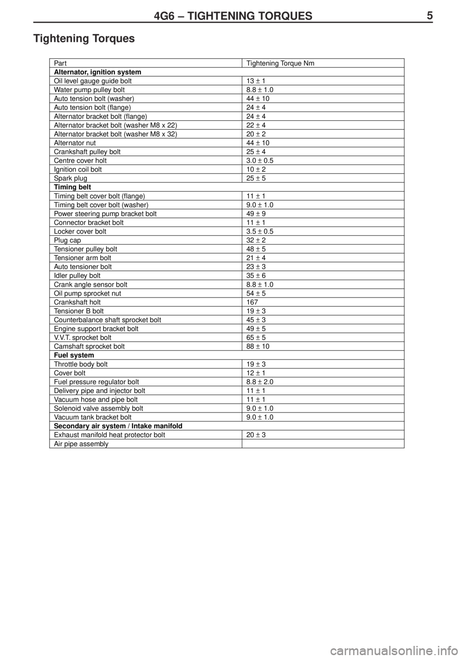
Tightening Torques
Par tTightening Torque Nm
Alternator, ignition system
Oil level gauge guide bolt13 ± 1
Water pump pulley bolt8.8 ± 1.0
Auto tension bolt (washer)44 ± 10
Auto tension bolt (flange)24 ± 4
Alternator bracket bolt (flange)24 ± 4
Alternator bracket bolt (washer M8 x 22)22 ± 4
Alternator bracket bolt (washer M8 x 32)20 ± 2
Alternator nut44 ± 10
Crankshaft pulley bolt25 ± 4
Centre cover holt3.0 ± 0.5
Ignition coil bolt10 ± 2
Spark plug25 ± 5
Timing belt
Timing belt cover bolt (flange)11 ± 1
Timing belt cover bolt (washer)9.0 ± 1.0
Power steering pump bracket bolt49 ± 9
Connector bracket bolt11 ± 1
Locker cover bolt3.5 ± 0.5
Plug cap32 ± 2
Tensioner pulley bolt48 ± 5
Tensioner arm bolt21 ± 4
Auto tensioner bolt23 ± 3
Idler pulley bolt35 ± 6
Crank angle sensor bolt8.8 ± 1.0
Oil pump sprocket nut54 ± 5
Crankshaft holt167
Tensioner B bolt19 ± 3
Counterbalance shaft sprocket bolt45 ± 3
Engine support bracket bolt49 ± 5
V.V.T. sprocket bolt65 ± 5
Camshaft sprocket bolt88 ± 10
Fuel system
Throttle body bolt19 ± 3
Cover bolt12 ± 1
Fuel pressure regulator bolt8.8 ± 2.0
Delivery pipe and injector bolt11 ± 1
Vacuum hose and pipe bolt11 ± 1
Solenoid valve assembly bolt9.0 ± 1.0
Vacuum tank bracket bolt9.0 ± 1.0
Secondary air system / Intake manifold
Exhaust manifold heat protector bolt20 ± 3
Air pipe assembly
Page 114 of 364
74G6 - TIGHTENING TORQUES
Par tTightening Torque
Oil control pump11 ± 1
Check valve30 ± 3
Eye bolt42 ± 2
Oil pipe11 ± 1
Oil pipe joint30 ± 3
Oil pump / Sump
Drain plug39 ± 5
Sump bolt9.0 ± 3.0
Oil screen bolt19 ± 3
Baffle plate bolt22 ± 4
Oil pressure switch10 ± 2
Oil cooler bypass valve54 ± 5
Relief plug44 ± 5
Oil filter bracket bolt19 ± 3
Plug cap23 ± 3
Flange bolt36 ± 3
Front case bolt23 ± 3
Oil pump cover bolt17 ± 2
Oil pump cover screw10 ± 2
Piston / Connecting rod
Connecting rod cap nut20 ± 2 _ +90° ~94°
Crankshaft / Cylinder block
Flywheel bolt132 ± 5
Rear plate bolt11 ± 1
Bell housing cover bolt (flange)10 ± 2
Bell housing cover bolt (washer)9.0 ± 1.0
Rear oil seal case bolt11 ± 1
Beam bearing cap bolt25 ± 2 _ +90° ~ 100°
Check valve32 ± 2
Turbocharger
Waste gate actuator bolt12 ± 1
Sealants
Par tSpecified Sealant
Cam position sensor support *MZ100191 or equivalent
Note : * indicates point where liquid gasket (FIPG) used
Page 119 of 364
124G6 – TIMING BELT
3. Push the V.V.T. sprocket firmly to the end and, holding the
hexagonal part of the camshaft with a wrench, check that the V.V.T.
sprocket does not rotate.
4. Hold the hexagonal section of the camshaft with a wrench and
tighten the V.V.T. sprocket bolt to the specified torque of 65 ±5 N-m.
5. Hold the hexagonal section of the camshaft with a wrench and
check that the V.V.T. sprocket does not rotate.
Note :
This check shows that the V.V.T. sprocket is locked at the maximum
delay angle by the interior pin.
Installation of plug cap
Note :
The washer must not be reused.
1. Install the washer on the plug cap.
2. Hold the hexagonal section of the camshaft with a wrench and
tighten the plug cap to the specified torque of 32±2 N-m.
�B�*
Page 132 of 364
254G6 – CRANKSHAFT / CYLINDER BLOCK
Crankshaft / Cylinder Block
Removal and Installation
Removal Procedure
1. Flywheel bolt
2. Flywheel
3. Rear plate
4. Bell housing cover
5. Rear oil seal case
6. Rear oil seal
7. Bearing cap bolt
8. Beam being cap9. Crankshaft bearing lower
10. Crankshaft
11.Crankshaft bearing upper
12. Thrust bearing
13. Check valve
14. Oil jet
15. Cylinder block
Apply engine oil to all
sliding parts before
installing. Bolt with washer : 9.0 ± 1.0 N-m
Flange bolt : 10 ± 2 N-m (supplementary part)
�A�*
�A�*
�
* 1�*
�
* 1�*
�
* 1�*
�
* 1�*
�
*1�*
Page 133 of 364
264G6 – CRANKSHAFT / CYLINDER BLOCK
Installation Service Point
Installation of crankshaft bearings
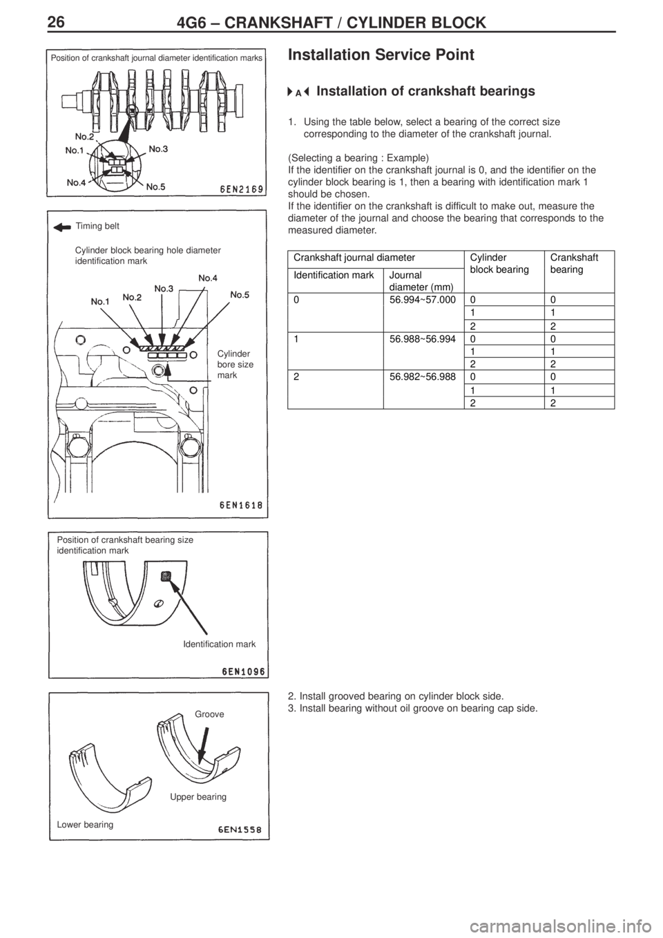
1. Using the table below, select a bearing of the correct size
corresponding to the diameter of the crankshaft journal.
(Selecting a bearing : Example)
If the identifier on the crankshaft journal is 0, and the identifier on the
cylinder block bearing is 1, then a bearing with identification mark 1
should be chosen.
If the identifier on the crankshaft is difficult to make out, measure the
diameter of the journal and choose the bearing that corresponds to the
measured diameter.
Crankshaft journal diameter
Identification mark Journal
diameter (mm)Cylinder
block bearingCrankshaft
bearing
00
11
056.994~57.000
22
00
11
156.988~56.994
22
00
11
256.982~56.988
22
2. Install grooved bearing on cylinder block side.
3. Install bearing without oil groove on bearing cap side.
Position of crankshaft journal diameter identification marks
Timing belt
Cylinder block bearing hole diameter
identification mark
Cylinder
bore size
mark
Position of crankshaft bearing size
identification mark
Identification mark
Groove
Lower bearingUpper bearing
�A�*
Page 138 of 364
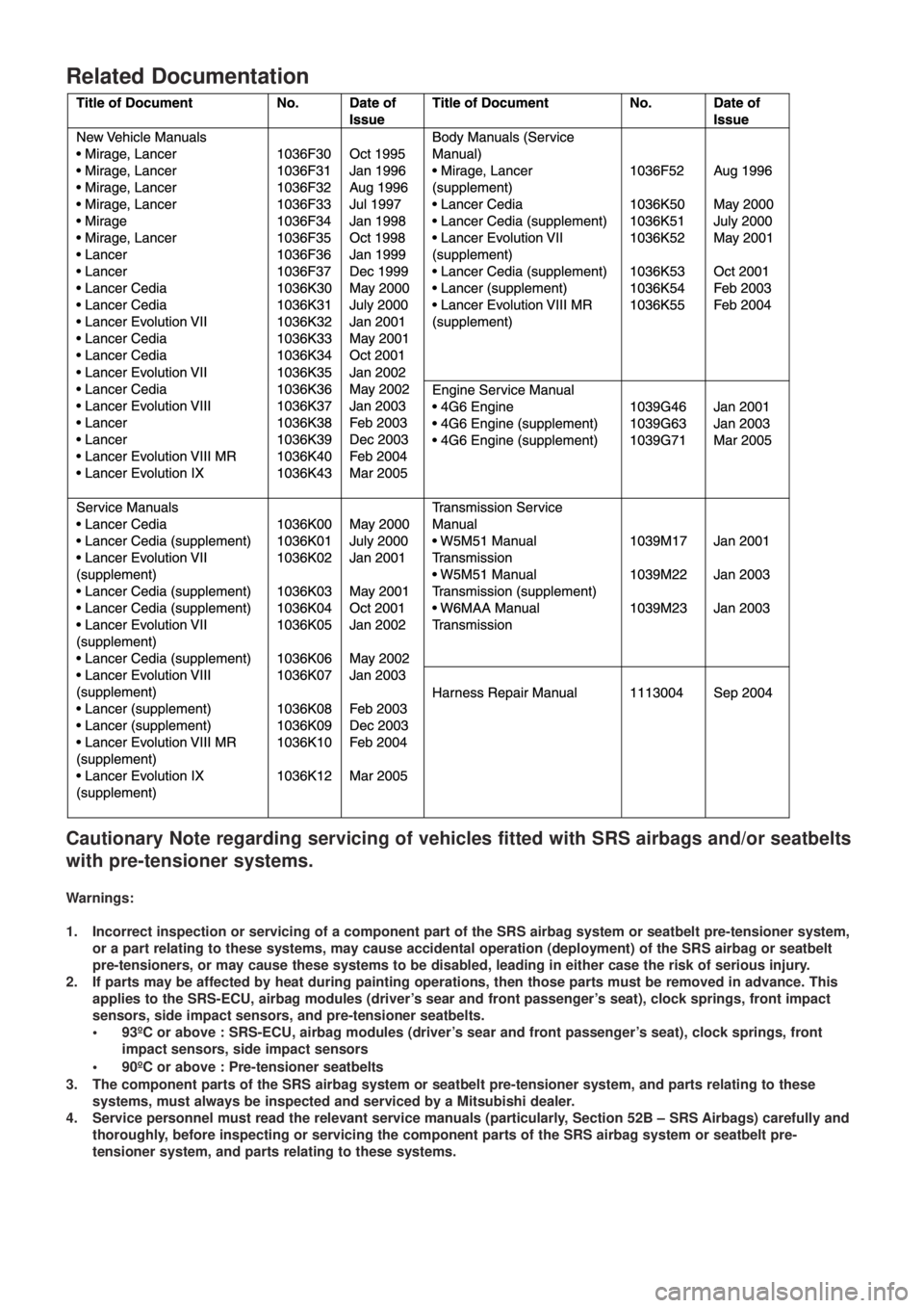
Related Documentation
Cautionary Note regarding servicing of vehicles fitted with SRS airbags and/or seatbelts
with pre-tensioner systems.
Warnings:
1. Incorrect inspection or servicing of a component part of the SRS airbag system or seatbelt pre-tensioner system,
or a part relating to these systems, may cause accidental operation (deployment) of the SRS airbag or seatbelt
pre-tensioners, or may cause these systems to be disabled, leading in either case the risk of serious injury.
2. If parts may be affected by heat during painting operations, then those parts must be removed in advance. This
applies to the SRS-ECU, airbag modules (driver’s sear and front passenger’s seat), clock springs, front impact
sensors, side impact sensors, and pre-tensioner seatbelts.
• 93ºC or above : SRS-ECU, airbag modules (driver’s sear and front passenger’s seat), clock springs, front
impact sensors, side impact sensors
•90ºC or above : Pre-tensioner seatbelts
3. The component parts of the SRS airbag system or seatbelt pre-tensioner system, and parts relating to these
systems, must always be inspected and serviced by a Mitsubishi dealer.
4. Service personnel must read the relevant service manuals (particularly, Section 52B – SRS Airbags) carefully and
thoroughly, before inspecting or servicing the component parts of the SRS airbag system or seatbelt pre-
tensioner system, and parts relating to these systems.