Page 468 of 1500

INPUT SIGNAL PROCEDURES
SIMPLIFIED WIRING SYSTEM (SWS)54B-468
STEP 13. Check the wiring harness between front power
window sub switch connector E-12 (terminals 1 and 2) and
ETACS-ECU connector C-217 (terminals 33 and 34).
NOTE: Also check intermediate connector C-26 for loose, cor-
roded, or damaged terminals, or terminals pushed back in the
connector. If intermediate connector C-26 is damaged, repair or
replace the connector as described in GROUP 00E, Harness
Connector Inspection P.00E-2.
Q: Is the wiring harness between front power window sub
switch connector E-12 (terminal 1 and 2) and
ETACS-ECU connector C-217 (terminals 33 and 34) in
good condition?
YES : Replace the ETACS-ECU. If the central door locking
system works normally, input signal from the door lock
switch (front power window sub switch) should be
normal.
NO : The wiring harness may be damaged or the
connector(s) may have loose, corroded or damaged
terminals, or terminals pushed back in the connector.
Repair the wiring harness as necessary. If the central
door locking system works normally, input signal from
the door lock switch (front power window sub switch)
should be normal.
Page 480 of 1500

CHECK AT ECU TERMINAL
SIMPLIFIED WIRING SYSTEM (SWS)54B-480
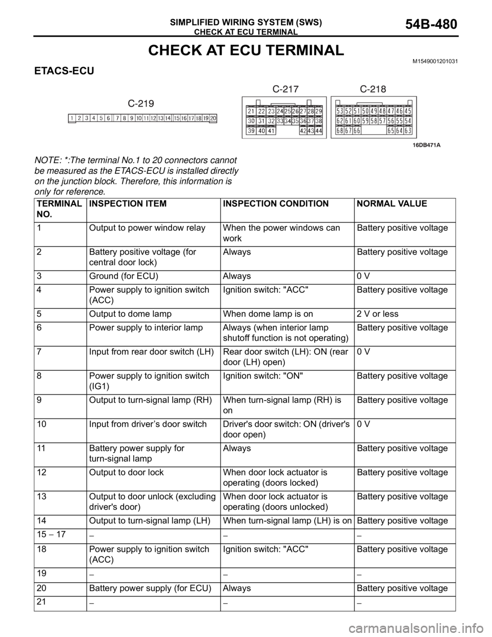
CHECK AT ECU TERMINALM1549001201031
ETACS-ECU
NOTE: *:The terminal No.1 to 20 connectors cannot
be measured as the ETACS-ECU is installed directly
on the junction block. Therefore, this information is
only for reference.
TERMINAL
NO.INSPECTION ITEM INSPECTION CONDITION NORMAL VALUE
1 Output to power window relay When the power windows can
workBattery positive voltage
2 Battery positive voltage (for
central door lock)Always Battery positive voltage
3 Ground (for ECU) Always 0 V
4 Power supply to ignition switch
(ACC)Ignition switch: "ACC" Battery positive voltage
5 Output to dome lamp When dome lamp is on 2 V or less
6 Power supply to interior lamp Always (when interior lamp
shutoff function is not operating)Battery positive voltage
7 Input from rear door switch (LH) Rear door switch (LH): ON (rear
door (LH) open)0 V
8 Power supply to ignition switch
(IG1)Ignition switch: "ON" Battery positive voltage
9 Output to turn-signal lamp (RH) When turn-signal lamp (RH) is
onBattery positive voltage
10 Input from driver’s door switch Driver's door switch: ON (driver's
door open)0 V
11 Battery power supply for
turn-signal lampAlways Battery positive voltage
12 Output to door lock When door lock actuator is
operating (doors locked)Battery positive voltage
13 Output to door unlock (excluding
driver's door)When door lock actuator is
operating (doors unlocked) Battery positive voltage
14 Output to turn-signal lamp (LH) When turn-signal lamp (LH) is on Battery positive voltage
15
17
18 Power supply to ignition switch
(ACC)Ignition switch: "ACC" Battery positive voltage
19
20 Battery power supply (for ECU) Always Battery positive voltage
21
Page 481 of 1500

CHECK AT ECU TERMINAL
SIMPLIFIED WIRING SYSTEM (SWS)54B-481
22 Output to door unlock (for
driver's door)When driver's door lock actuator
is operating (doors unlocked)Battery positive voltage
23, 24
25 Input of door lock key cylinder
switch (UNLOCK) signalDoor lock key cylinder switch:
UNLOCK0 V
26
28
29 Input of rear door lock actuator
(UNLOCK) signalRear door lock actuator:
UNLOCK0 V
30 Input of key reminder switch
signalKey reminder switch: ON (when
ignition key is removed)0 V
31, 32
33 Input of door lock switch (LOCK)
signalDoor lock switch (incorporated in
power window switch): LOCK0 V
34 Input of door lock switch
(UNLOCK) signalDoor lock switch (incorporated in
power window switch): UNLOCK0 V
35 Input from rear door switch (RH) Rear door switch (RH): ON (rear
door (RH) open)0 V
36 Input of driver's door lock
actuator (UNLOCK) signalDriver's door lock actuator:
UNLOCK0 V
37 Input from trunk lid latch
assemblyTrunk lid latch: ON (trunk open) 0 V
38 Ground (for sensor) Always 0 V
39
41
42 Input of door lock key cylinder
switch (LOCK) signalDoor lock key cylinder switch:
LOCK0 V
43 Input of front passenger's door
lock actuator (UNLOCK) signalFront passenger’s door lock
actuator: UNLOCK0 V
44 Output to horn relay When a horn sounds by the
keyless entry horn answerback
function2 V or less
45 Output to data link connector When DTC sets 0
12 V (pulse signal)
When input check signal is
output0
12 V (when input
pulse signal is
fluctuating)
46 Output to trunk lamp When trunk lid latch on. 0 V
47
48 Input of fog lamp switch signal Fog lamp switch: ON 0 V
49 Input of hazard warning lamp
switch signalHazard warning lamp switch: ON
(When the switch is depressed)0 V
50 Ground (for sensor) Always 0 V
51 Key Ring Antenna (+) 0 V 0 V
52 Key Ring Antenna (-) 0 V 0 V
53 SWS communication line Always 0
12 V (pulse signal) TERMINAL
NO.INSPECTION ITEM INSPECTION CONDITION NORMAL VALUE
Page 503 of 1500
Page 504 of 1500
Page 505 of 1500
Page 506 of 1500
DOOR TRIM
INTERIOR52A-17
DISASSEMBLY AND ASSEMBLYM1521006900100
DISASSEMBLY STEPS
1. ASSIST GRIP
2. POWER WINDOW MAIN SWITCH
3. REMOTE CONTROLLED MIRROR
SWITCH4. POWER WINDOW MEIN SWITCH
PA N E L
5. ARMREST BRACKET
6. ARMREST
7. FRONT DOOR TRIMDISASSEMBLY STEPS
Page 507 of 1500
DOOR TRIM
INTERIOR52A-18
DISASSEMBLY STEPS
1. POWER WINDOW SUB SWITCH
2. POWER WINDOW SUB SWITCH
PA N E L3. ARMREST
4. REAR DOOR TRIMDISASSEMBLY STEPS