Page 1356 of 1500
AUTO-CRUISE CONTROL
ENGINE AND EMISSION CONTROL17-25
STEP 6. Check intermediate connector C-29, auto-cruise
control switch connector C-302 and clock spring
connectors C-303 and C-306 for loose, corroded or
damaged terminals, or terminals pushed back in the
connector.
Q: Are the connectors and terminals in good condition?
YES : Go to Step 7.
NO : Repair the faulty connector if possible or as
recommended, replace complete wiring harness.
(Refer to GROUP 00E, Harness Connector Inspection
P.00E-2). Install the air bag module (driver’s side).
(Refer to GROUP 52B, Air Bag Modules and Clock
Spring P.52B-237). Then go to Step 18.
Page 1357 of 1500

AUTO-CRUISE CONTROL
ENGINE AND EMISSION CONTROL17-26
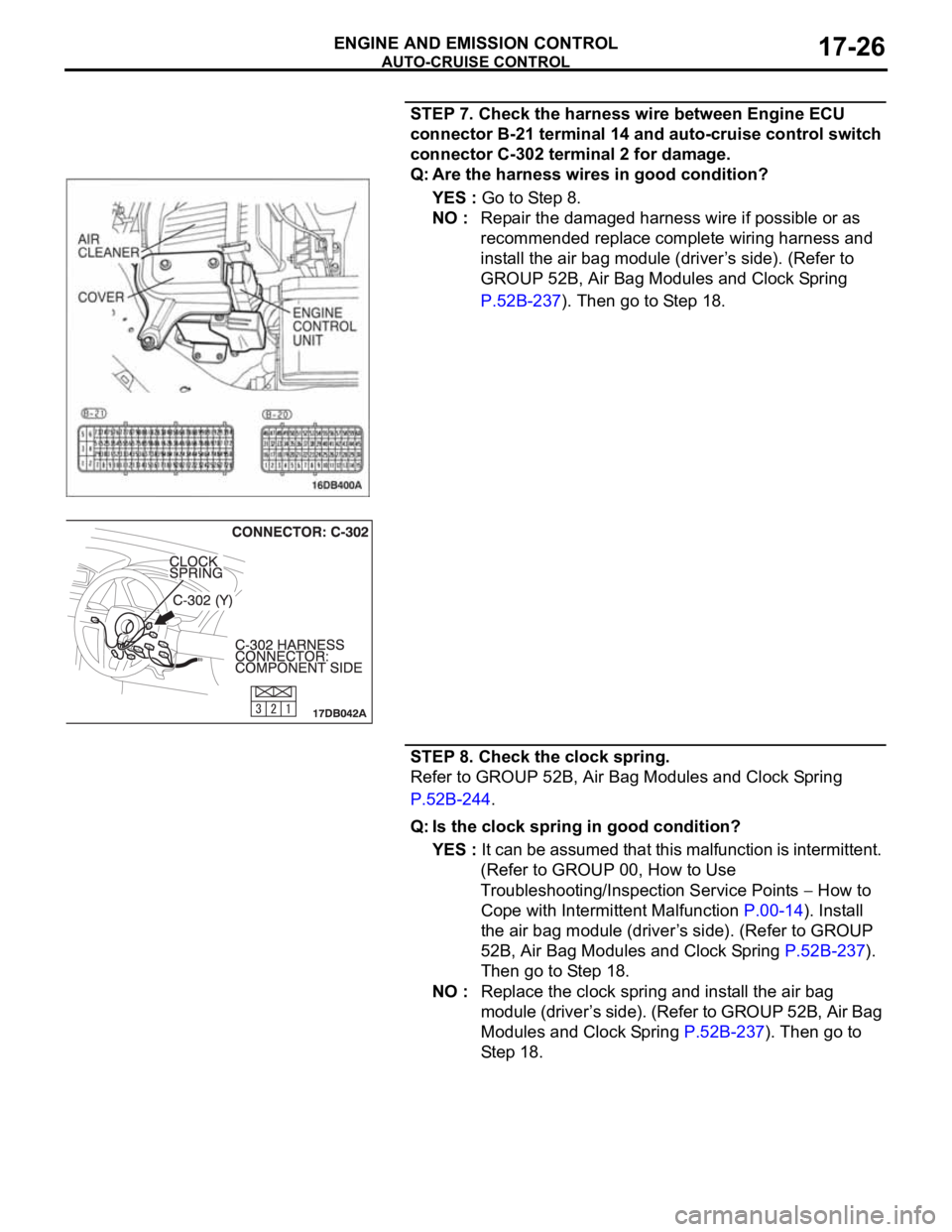
STEP 7. Check the harness wire between Engine ECU
connector B-21 terminal 14 and auto-cruise control switch
connector C-302 terminal 2 for damage.
Q: Are the harness wires in good condition?
YES : Go to Step 8.
NO : Repair the damaged harness wire if possible or as
recommended replace complete wiring harness and
install the air bag module (driver’s side). (Refer to
GROUP 52B, Air Bag Modules and Clock Spring
P.52B-237). Then go to Step 18.
STEP 8. Check the clock spring.
Refer to GROUP 52B, Air Bag Modules and Clock Spring
P.52B-244.
Q: Is the clock spring in good condition?
YES : It can be assumed that this malfunction is intermittent.
(Refer to GROUP 00, How to Use
Troubleshooting/Inspection Service Points
How to
Cope with Intermittent Malfunction P.00-14). Install
the air bag module (driver’s side). (Refer to GROUP
52B, Air Bag Modules and Clock Spring P.52B-237).
Then go to Step 18.
NO : Replace the clock spring and install the air bag
module (driver’s side). (Refer to GROUP 52B, Air Bag
Modules and Clock Spring P.52B-237). Then go to
Step 18.
Page 1359 of 1500
AUTO-CRUISE CONTROL
ENGINE AND EMISSION CONTROL17-28
STEP 11. Check Engine ECU connector B-21 for loose,
corroded or damaged terminals, or terminals pushed back
in the connector.
Q: Are the connector and terminals in good condition?
YES : Install the air bag module (driver’s side). (Refer to
GROUP 52B, Air Bag Modules and Clock Spring
P.52B-237). Then go to Step 17.
NO : Repair the faulty connector if possible, or as
recommended, replace complete wiring harness.
(Refer to GROUP 00E, Harness Connector Inspection
P.00E-2). Install the air bag module (driver’s side).
(Refer to GROUP 52B, Air Bag Modules and Clock
Spring P.52B-237). Then go to Step 18.
Page 1361 of 1500
AUTO-CRUISE CONTROL
ENGINE AND EMISSION CONTROL17-30
Q: Are the connectors and terminals in good condition?
YES : Go to Step 13.
NO : Repair the faulty connector if possible, or as
recommended, replace complete wiring harness.
(Refer to GROUP 00E, Harness Connector Inspection
P.00E-2). Install the air bag module (driver’s side).
(Refer to GROUP 52B, Air Bag Modules and Clock
Spring P.52B-237). Then go to Step 18.
STEP 13. Check the harness wire between Engine ECU
connector B-21 terminal 15 and auto-cruise control switch
connector C-302 terminal 3 for damage.
Q: Are the harness wires in good condition?
YES : Go to Step 14.
NO : Repair the damaged harness wire if possible, or
replace complete wiring harness and install the air
bag module (driver’s side). (Refer to GROUP 52B, Air
Bag Modules and Clock Spring P.52B-237). Then go
to Step 18.
Page 1362 of 1500

AUTO-CRUISE CONTROL
ENGINE AND EMISSION CONTROL17-31
STEP 14. Check the clock spring.
Refer to GROUP 52B, Air Bag Modules and Clock Spring
P.52B-244.
Q: Is the clock spring in good condition?
YES : It can be assumed that this malfunction is intermittent.
(Refer to GROUP 00, How to Use
Troubleshooting/Inspection Service Points
How to
Cope with Intermittent Malfunction P.00-14). Install
the air bag module (driver’s side). (Refer to GROUP
52B, Air Bag Modules and Clock Spring P.52B-237).
Then go to Step 18.
NO : Replace the clock spring and install the air bag
module (driver’s side). (Refer to GROUP 52B, Air Bag
Modules and Clock Spring P.52B-237). Then go to
Step 18.
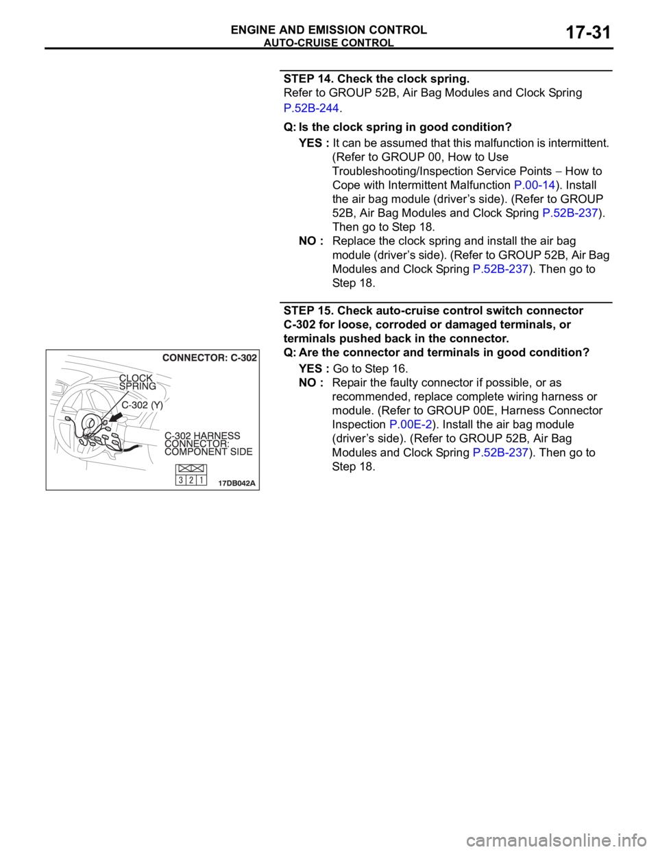
STEP 15. Check auto-cruise control switch connector
C-302 for loose, corroded or damaged terminals, or
terminals pushed back in the connector.
Q: Are the connector and terminals in good condition?
YES : Go to Step 16.
NO : Repair the faulty connector if possible, or as
recommended, replace complete wiring harness or
module. (Refer to GROUP 00E, Harness Connector
Inspection P.00E-2). Install the air bag module
(driver’s side). (Refer to GROUP 52B, Air Bag
Modules and Clock Spring P.52B-237). Then go to
Step 18.
Page 1370 of 1500
AUTO-CRUISE CONTROL
ENGINE AND EMISSION CONTROL17-39
STEP 5. Check the harness wire between Engine ECU
connector B-21 terminal 18 and stoplamp switch
connector C-30 terminal 1 for damage.
Q: Is the harness wire in good condition?
YES : Go to Step 13.
NO : Repair the damaged harness wire if possible, or as
recommended, replace complete wiring harness.
Then go to Step 22.
Page 1394 of 1500

AUTO-CRUISE CONTROL
ENGINE AND EMISSION CONTROL17-63
CIRCUIT OPERATION
The Engine ECU detects "CRUISE" (MAIN) switch
"ON" signal to illuminate the "CRUISE" indicator
lamp on the combination meter.
.
COMMENT
Connector(s), wiring harness in the CAN bus line
between the Engine ECU and the combination
meter, power supply to the Engine ECU, the combi-
nation meter, the Engine ECU may be defective.
.
TROUBLESHOOTING HINTS
Malfunction of the combination meter.
Damaged harness or connector.
Malfunction of the Engine ECU.
Circuit drawings
Refer to circuit diagrams GROUP-90
Refer to configuration diagrams GROUP-80
Refer to component locations GROUP-70
DIAGNOSIS
Required Special Tools:
MB991958: Diagnostic Tool (MUT-III Sub Assembly)
MB991824: V.C.I.
MB991827: MUT-III USB Cable
MB991910: MUT-III Main Harness A
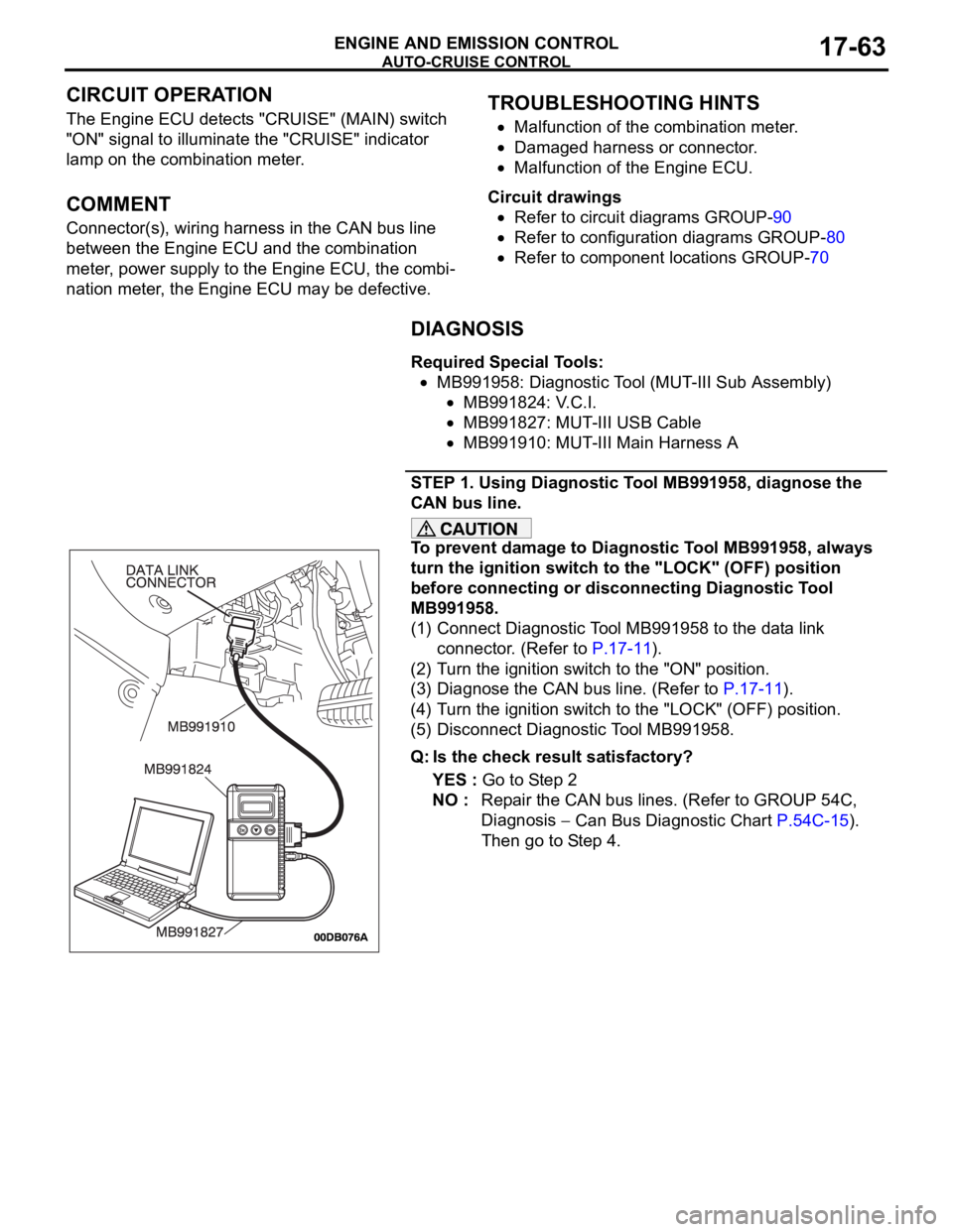
STEP 1. Using Diagnostic Tool MB991958, diagnose the
CAN bus line.
To prevent damage to Diagnostic Tool MB991958, always
turn the ignition switch to the "LOCK" (OFF) position
before connecting or disconnecting Diagnostic Tool
MB991958.
(1) Connect Diagnostic Tool MB991958 to the data link
connector. (Refer to P.17-11).
(2) Turn the ignition switch to the "ON" position.
(3) Diagnose the CAN bus line. (Refer to P.17-11).
(4) Turn the ignition switch to the "LOCK" (OFF) position.
(5) Disconnect Diagnostic Tool MB991958.
Q: Is the check result satisfactory?
YES : Go to Step 2
NO : Repair the CAN bus lines. (Refer to GROUP 54C,
Diagnosis
Can Bus Diagnostic Chart P.54C-15).
Then go to Step 4.
Page 1397 of 1500

AUTO-CRUISE CONTROL
ENGINE AND EMISSION CONTROL17-66
If the air intake duct is removed from the throttle body take great care to keep fingers away
from the throttle plate. The drive motor has very high torque and is capable of random move-
ment at any time. Do not under any circumstances activate the throttle plate by hand.
When removing the throttle body from the intake manifold disconnect the wiring first. During
replacement connect the wiring last.
Do not activate the throttle body using a DC suppy to test the motor,as permanent damage to
the throttle body will result.
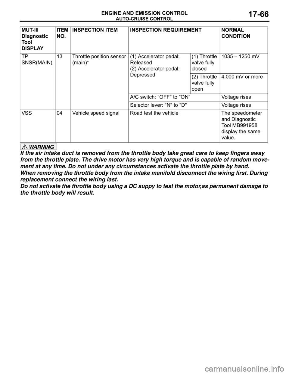
TP
SNSR(MAIN)13 Throttle position sensor
(main)*(1) Accelerator pedal:
Released
(2) Accelerator pedal:
Depressed(1) Throttle
valve fully
closed1035 1250 mV
(2) Throttle
valve fully
open4,000 mV or more
A/C switch: "OFF" to "ON" Voltage rises
Selector lever: "N" to "D" Voltage rises
VSS 04 Vehicle speed signal Road test the vehicle The speedometer
and Diagnostic
Tool MB991958
display the same
value. MUT-III
Diagnostic
To o l
DISPLAYITEM
NO.INSPECTION ITEM INSPECTION REQUIREMENT NORMAL
CONDITION