2005 MITSUBISHI 380 wiring
[x] Cancel search: wiringPage 965 of 1500

INTAKE MANIFOLD PLENUM
INTAKE AND EXHAUST15-6
Required Special Tool:
MD998412: Guide
INSTALLATION SERVICE POINT
.
>>A<< INTAKE MANIFOLD PLENUM INSTALLA-
TION
Use special tool MD998412 to install the intake manifold ple-
num.
REMOVAL STEPS
1. MANIFOLD ABSOLUTE
PRESSURE SENSOR
CONNECTOR
2. CONTROL WIRING HARNESS
AND INJECTOR WIRING
HARNESS COMBINATION
CONNECTOR
3. CRANKSHAFT POSITION
SENSOR CONNECTOR
4. KNOCK SENSOR CONNECTOR
5. POWER STEERING PRESSURE
SWITCH CONNECTOR
6. EVAPORATIVE EMISSION
PURGE SOLENOID CONNECTOR
8. VACUUM HOSE CONNECTION
9. PURGE HOSE
10. POWER STEERING PRESSURE
HOSE CLAMP
11. POWER STEERING PRESSURE
HOSE CLAMP BRACKET
12. INTAKE MANIFOLD PLENUM
STAY, REARSTEERING GEAR AND LINKAGE
PROTECTOR (REFER TO 37,
STEERING GEAR BOX AND
LINKAGE P.37-30)
POWER STEERING OIL PUMP
(REFER TO 37, POWER
STEERING OIL PUMP ASSEMBLY
P.37-43)
15. POWER STEERING OIL PUMP
BRACKET CONNECTING BOLT
16. INTAKE MANIFOLD PLENUM
STAY, FRONT
>>A<<17. INTAKE MANIFOLD PLENUM
18. INTAKE MANIFOLD PLENUM
GASKET
19. VACUUM PIPE
20. EVAPORATIVE EMISSION
PURGE SOLENOID ASSEMBLY
23. HARNESS BRACKET
24. MANIFOLD ABSOLUTE
PRESSURE SENSOR
25. O-RINGREMOVAL STEPS (Continued)
Page 984 of 1500

CHARGING SYSTEM
ENGINE ELECTRICAL16-7
ON-VEHICLE SERVICE
ALTERNATOR OUTPUT WIRE VOLTAGE DROP TESTM1161000900669
Required Special Tool:
: Diagnostic Tool (MUT-III)
MB991824: V.C.I.
MB991827: MUT-III USB Cable
MB991910: MUT-III Main Harness A
This test determines whether the wiring from the
alternator "B" terminal to the positive battery terminal
(including the fusible link) is in good condition or not:
Battery posts, terminals and related acces-
sories contain lead and lead compounds.
WASH HANDS AFTER HANDLING.
1. Always be sure to check the following before the
test.
Alternator installation
Alternator drive belt tension (Refer to GROUP 00,
General
Maintenance Service Drive Belts
(For Alternator, Power Steering Pump and Air
Conditioning) (Check) P.00-39.)
Fusible link
Abnormal noise from the alternator while the
engine is running.2. Turn the ignition switch to the "LOCK" (OFF)
position.
3. Disconnect the negative battery cable.
4. Connect a clamp-type DC test ammeter with a
range of 0
100 A to the alternator "B" terminal
output wire.
NOTE: The way of disconnecting the alternator
output wire and of connecting the ammeter is pos-
sibly not found the problem that the output current
is dropping due to the insufficient connection
between terminal "B" and the output wire.
5. Connect a digital-type voltmeter between the
alternator "B" terminal and the positive battery
terminal. (Connect the positive lead of the
voltmeter to the "B" terminal, and then connect the
negative lead of the voltmeter to the positive
battery cable.)
6. Reconnect the negative battery cable.
7. Connect an engine tachometer or diagnostic tool.
8. Leave the hood open.
9. Start the engine.
Page 985 of 1500

CHARGING SYSTEM
ENGINE ELECTRICAL16-8
10.With the engine running at 2,500 r/min, turn the
headlights and other lights on and off to adjust the
alternator load so that the value displayed on the
ammeter is slightly above 30 A.
Read the voltmeter. Voltage reading at or below
limit value means voltage drop between alternator
and battery is OK.
Limit value: maximum 0.3 V
NOTE: When the alternator output is high and the
value displayed on the ammeter does not
decrease to 30 A, set the value to 40 A. Read the
value displayed on the voltmeter at this time.
In this case the limit value becomes maximum 0.4
V.
Adjust the engine speed by gradually decreasing
it until the value displayed on the ammeter is 30
A. Take a reading of the value displayed on the
voltmeter at this time.11.If the value displayed on the voltmeter is above
the limit value, there is probably a malfunction in
the alternator output wire. Check the wiring
between the alternator "B" terminal and the
positive battery terminal (including fusible link).
If a terminal is not sufficiently tight or if the
harness has become discolored due to
overheating, repair and then test again.
12.After the test, run the engine at idle.
13.Turn off all lights and turn the ignition switch to the
"LOCK" (OFF) position.
14.Disconnect the engine tachometer or diagnostic
tool.
15.Disconnect the negative battery cable.
16.Disconnect the ammeter and voltmeter.
17.Connect the negative battery cable.
18.Run the engine for 10 minutes at an idle.
OUTPUT CURRENT TESTM1161001000670
Page 1047 of 1500

WINDSHIELD WIPER AND WASHER
EXTERIOR51-14
WINDSHIELD WIPER AND WASHER
GENERAL DESCRIPTIONM1511000100558
WINDSHIELD WIPER AND WASHER
OPERATION
.
WINDSHIELD LOW-SPEED (AND
HIGH-SPEED) WIPER OPERATION
If the windshield low-speed wiper switch is turned
to the ON position with the ignition switch at the
"ACC" or "ON" position, the column switch sends
a low-speed wiper ON and high-speed wiper OFF
signals to the front-ECU. This turns the wiper sig-
nal on and the wiper speed control relay off
(low-speed), causing the wipers to operate at
low-speed.
If the windshield high-speed wiper switch is
turned to the ON position, the column switch
sends a low-speed wiper OFF and high-speed
wiper ON signals to the front-ECU. This turns
both the wiper signal and the wiper speed control
relay on (high-speed), causing the wipers to
operate at high-speed.
NOTE: The windshield wiper speed is adjustable
with the built-in wiper speed control relay.
High-speed operations take place when the wiper
speed control relay is set to "ON" and low-speed
operations take place when the wiper speed control
relay is set to "OFF".
.
WINDSHIELD INTERMITTENT WIPER
OPERATION
The ETACS-ECU calculates the wiper operation
interval according to the voltage signal sent from the
column switch. Then the ETACS-ECU sends a signal
to the front-ECU. The front-ECU determines the
wiper operation interval and turns on the wiper relay
signal relay. This causes the wiper auto stop relay to
turn on. Then the wiper auto stop relay will turn off
after the wipers reach the park position. This causes
the wiper signal relay and then the wipers to turn off.
If the wiper signal relay remains off for the wiper
operation interval, the relay turns on again, causing
the wipers to operate in intermittent mode.
.
WINDSHIELD MIST WIPER OPERATION
If the windshield mist wiper switch is turned to the
ON position with the ignition switch at the "ACC"
or "ON" position, the mist wiper high-speed oper-
ation signal is sent to the front-ECU. This signal
turns on the wiper speed control relay, causing
the wipers to work at high-speed while the mist
switch is on.
While the windshield mist wiper switch remains
turned on when the intermittent mode is still work-
ing, the wipers work as the mist wiper. However,
the wipers return to the intermittent mode again
when the switch is changed back to "INT" posi-
tion.
To prevent the windshield mist wiper from operat-
ing when the windshield wiper switch is turned
OFF, the windshield mist wiper does not work for
0.5 second after the windshield intermittent wiper
switch, the windshield low-speed wiper switch
and the windshield high-speed wiper switch are
turned OFF.
.
WINDSHIELD WASHER OPERATION
If the windshield washer switch is turned to the
ON position with the ignition switch at "ACC" or
"ON" position, the windshield washer ON signal is
sent to the front-ECU. After 0.3 second, the wind-
shield wiper signal turns on. After the windshield
washer switch signal turns off, the windshield
wiper signal turns off in three seconds.
If the windshield washer switch is turned on while
the windshield wiper is at intermittent mode, and
the windshield washer switch is turned OFF
within 0.2 second, the wiper works only once to
perform mist operation. When the windshield
washer switch is turned on for more than 0.2 sec-
ond, the wiper performs the same movement as
normal condition from the time when 0.2 second
has elapsed, and then returns to intermittent
operation.
WINDSHIELD WIPER AND WASHER DIAGNOSISM1511000700389
The windshield wiper and washer are controlled by
the Simplified Wiring System (SWS). For trouble-
shooting, refer to GROUP 54B, SWS Diagnosis
P.54B-10.NOTE: Even when the ETACS-ECU has failed, the
windshield wiper can work at low speed as fail-safe
mode. (Normally, the windshield wiper operates
when the ignition switch is at the "ACC" position. But,
if it enters the fail-safe mode, the wiper can operate
only when the ignition switch is at the "ON" position.)
Page 1090 of 1500

DOOR
BODY42-23
DOOR
GENERAL DESCRIPTIONM1423000100246
OPERATION
.
CENTRAL DOOR LOCKING SYSTEM
The central door locking system operates the door
lock actuator to lock or unlock the doors and the fuel
lid door using the door lock switch built into the front
power window (main or sub) switch or key cylinder
built into the driver's side door outside handle. The
system has the following operations and features:
All doors and fuel lid door can be locked using the
door lock switch built into the front power window
(main or sub
Insert the key into the driver's key cylinder and
turn once to the unlock side to unlock the driver's
door and fuel lid door. Turn the key once again to
the unlock side to unlock all doors and fuel lid
door.
The key reminder function automatically unlocks
all doors when door lock operation is performed
and the front doors are opened while the key is
inserted into the ignition switch.
.
POWER WINDOWS
When the power window (main or sub) switch is
operated, the door windows will open or close. This
system has the following operations and features:
A power window lock switch on the power win-
dow main switch prevents the door window glass
from opening/closing with the front passenger's
and rear power window sub switch.
The power window of the door window glass can
be opened/closed for 30 seconds with the timer
function after the ignition switch is turned OFF.
(The timer expires if the front door
opened when the timer is in operation).
The power window main switch contains a
one-touch down switch that will automatically
open the driver's side door window only.
CENTRAL DOOR LOCKING SYSTEM DIAGNOSISM1427000700217
The central door locking system is controlled by the
simplified wiring system (SWS). Refer to GROUP
54B, SWS Diagnosis P.54B-57.
POWER WINDOW DIAGNOSISM1429000700224
The power window is controlled by the simplified wir-
ing system (SWS). Refer to GROUP 54B, SWS
Diagnosis P.54B-57.
DOOR DIAGNOSIS
INTRODUCTION TO GLASS AND DOOR DIAGNOSISM1423007300241
Glass and door faults include water leaks and
improper opening and closing. Causes for these
faults can include faults in the glass, weatherstrip,
drain hole, waterproof film or door installation.
GLASS AND DOOR DIAGNOSTIC TROUBLESHOOTING STRATEGYM1423006700246
Use these steps to plan your diagnostic strategy. If
you follow them carefully, you will be sure that you
have exhausted most of the possible ways to find a
glass and door fault.
1. Gather information from the customer.2. Verify that the condition described by the
customer exists.
3. Find the malfunction by following the Symptom
Chart.
4. Verify malfunction is eliminated.
Page 1135 of 1500

KEYLESS ENTRY SYSTEM
BODY42-68
If none of the doors is opened or the ignition key
is not inserted in the ignition switch within 30 sec-
onds after the doors are unlocked using the
transmitter, the ETACS-ECU will relock the doors
automatically. This is called "Timer lock function."
This timer lock function prevents accidental
unlocking of doors. The adjustment function
allows you to change the timer lock period from 30 seconds (default setting) to 60, 120 or 180
seconds. For further details on using the
multi-center display (middle grade type) to adjust
the timer lock period, refer to GROUP 54B,
On-vehicle Service P.54B-486.
NOTE: The timer lock period begins when the doors
are unlocked, and ends when the doors is relocked
automatically.
KEYLESS ENTRY SYSTEM DIAGNOSISBGBCJGAI
The keyless entry system is controlled by the Simpli-
fied Wiring System (SWS). Refer to GROUP 54B,
SWS Diagnosis P.54B-57.
SPECIAL TOOLBGBBBGDH
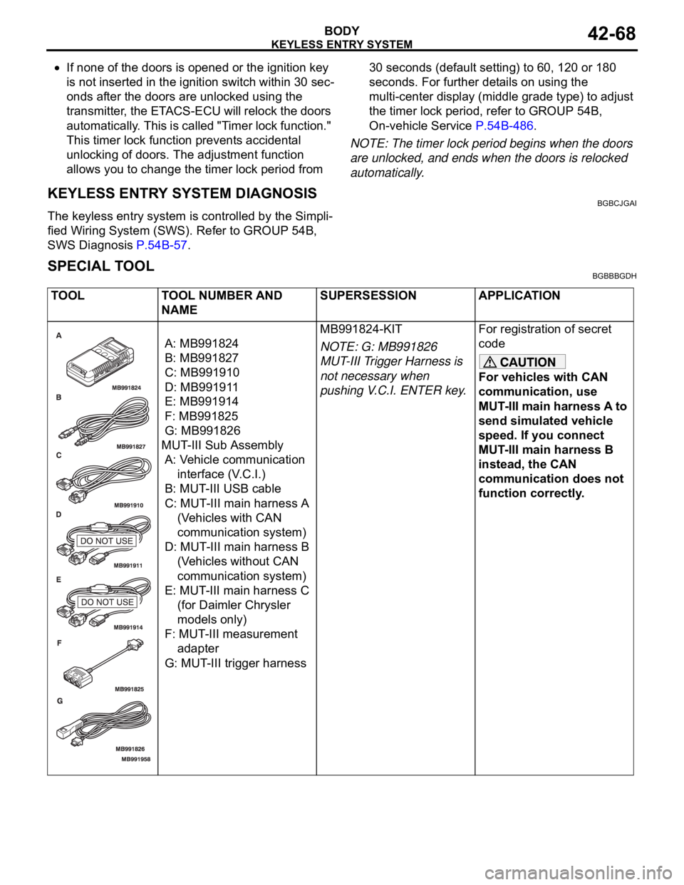
TOOL TOOL NUMBER AND
NAMESUPERSESSION APPLICATION
A: MB991824
B: MB991827
C: MB991910
D: MB991911
E: MB991914
F: MB991825
G: MB991826
MUT-III Sub Assembly
A: Vehicle communication
interface (V.C.I.)
B: MUT-III USB cable
C: MUT-III main harness A
(Vehicles with CAN
communication system)
D: MUT-III main harness B
(Vehicles without CAN
communication system)
E: MUT-III main harness C
(for Daimler Chrysler
models only)
F: MUT-III measurement
adapter
G: MUT-III trigger harnessMB991824-KIT
NOTE: G: MB991826
MUT-III Trigger Harness is
not necessary when
pushing V.C.I. ENTER key.For registration of secret
code
For vehicles with CAN
communication, use
MUT-III main harness A to
send simulated vehicle
speed. If you connect
MUT-III main harness B
instead, the CAN
communication does not
function correctly.
Page 1142 of 1500

SUNROOF ASSEMBLY
BODY42-75
SUNROOF ASSEMBLY
GENERAL DESCRIPTIONM1426000100234
A motor-driven inner slide-type glass sunroof with a
tilt-up mechanism is available in some models as a
standard or optional equipment. Even when the sun-
roof is fully closed, a sufficient amount of lighting and
a feeling of openness can still be obtained by open-
ing the sunroof sunshade.
SUNROOF DIAGNOSISM1426000700311
The sunroof system is controlled by the Simplified
Wiring System (SWS). Refer to GROUP 54B, SWS
Diagnosis P.54B-57.
SPECIAL TOOLM1426000600228
ON-VEHICLE SERVICE
WAT E R T ES TM1426000900274
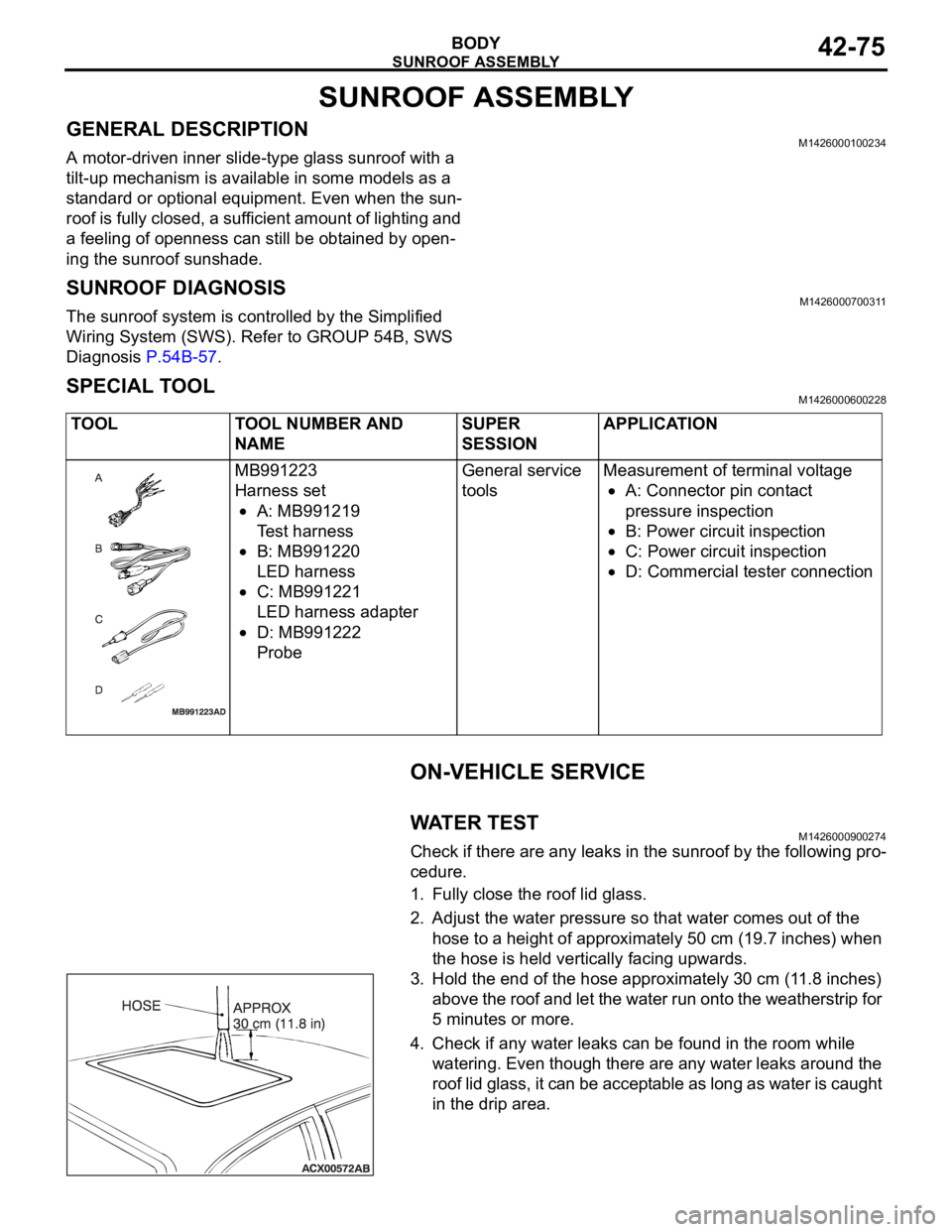
Check if there are any leaks in the sunroof by the following pro-
cedure.
1. Fully close the roof lid glass.
2. Adjust the water pressure so that water comes out of the
hose to a height of approximately 50 cm (19.7 inches) when
the hose is held vertically facing upwards.
3. Hold the end of the hose approximately 30 cm (11.8 inches)
above the roof and let the water run onto the weatherstrip for
5 minutes or more.
4. Check if any water leaks can be found in the room while
watering. Even though there are any water leaks around the
roof lid glass, it can be acceptable as long as water is caught
in the drip area. TOOL TOOL NUMBER AND
NAMESUPER
SESSIONAPPLICATION
MB991223
Harness set
A: MB991219
Test harness
B: MB991220
LED harness
C: MB991221
LED harness adapter
D: MB991222
ProbeGeneral service
toolsMeasurement of terminal voltage
A: Connector pin contact
pressure inspection
B: Power circuit inspection
C: Power circuit inspection
D: Commercial tester connection
Page 1189 of 1500

BRAKE PEDAL
BASIC BRAKE SYSTEM35A-24
BRAKE PEDAL
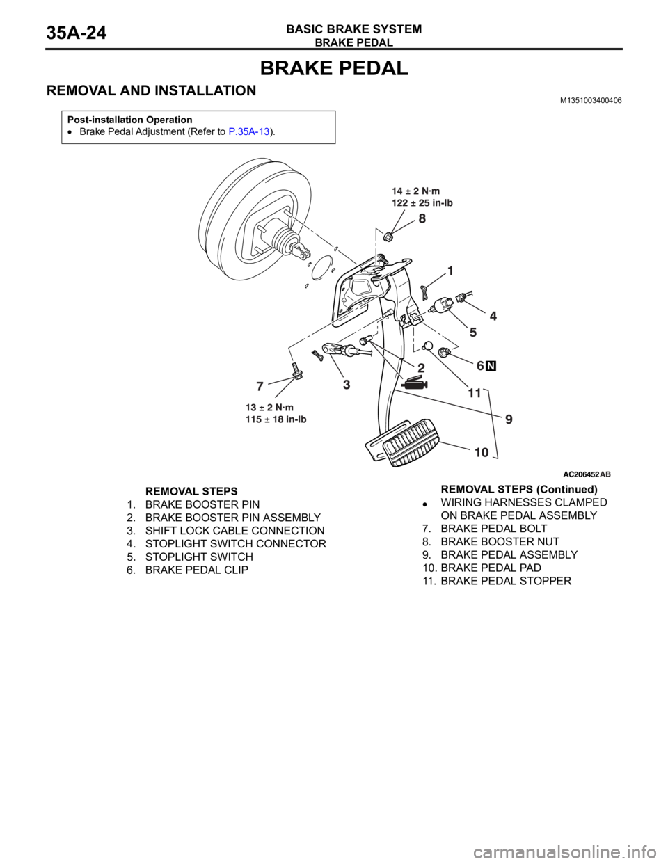
REMOVAL AND INSTALLATIONM1351003400406
Post-installation Operation
Brake Pedal Adjustment (Refer to P.35A-13).
REMOVAL STEPS
1. BRAKE BOOSTER PIN
2. BRAKE BOOSTER PIN ASSEMBLY
3. SHIFT LOCK CABLE CONNECTION
4. STOPLIGHT SWITCH CONNECTOR
5. STOPLIGHT SWITCH
6. BRAKE PEDAL CLIPWIRING HARNESSES CLAMPED
ON BRAKE PEDAL ASSEMBLY
7. BRAKE PEDAL BOLT
8. BRAKE BOOSTER NUT
9. BRAKE PEDAL ASSEMBLY
10. BRAKE PEDAL PAD
11. BRAKE PEDAL STOPPERREMOVAL STEPS (Continued)