Page 907 of 1500

HOW TO DIAGNOSE
GENERAL 00E-6
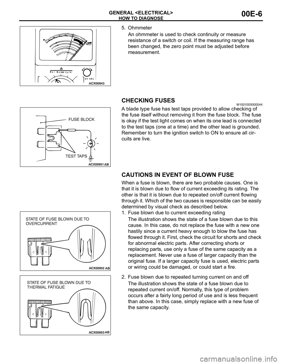
5. Ohmmeter
An ohmmeter is used to check continuity or measure
resistance of a switch or coil. If the measuring range has
been changed, the zero point must be adjusted before
measurement.
CHECKING FUSESM1001005000044
A blade type fuse has test taps provided to allow checking of
the fuse itself without removing it from the fuse block. The fuse
is okay if the test light comes on when its one lead is connected
to the test taps (one at a time) and the other lead is grounded.
Remember to turn the ignition switch to ON to ensure all cir-
cuits are live.
CAUTIONS IN EVENT OF BLOWN FUSE
When a fuse is blown, there are two probable causes. One is
that it is blown due to flow of current exceeding its rating. The
other is that it is blown due to repeated on/off current flowing
through it. Which of the two causes is responsible can be easily
determined by visual check as described below.
1. Fuse blown due to current exceeding rating
The illustration shows the state of a fuse blown due to this
cause. In this case, do not replace the fuse with a new one
hastily since a current heavy enough to blow the fuse has
flowed through it. First, check the circuit for shorts and check
for abnormal electric parts. After correcting shorts or
replacing parts, use only a fuse of the same capacity as a
replacement. Never use a fuse of larger capacity than the
original fuse. If a larger capacity fuse is used, electric parts
or wiring could be damaged, or could start a fire.
2. Fuse blown due to repeated turning current on and off
The illustration shows the state of a fuse blown due to
repeated current on/off. Normally, this type of problem
occurs after a fairly long period of use and is less frequent
than above. In this case, simply replace with a new fuse of
the same capacity.
Page 910 of 1500

HOW TO DIAGNOSE
GENERAL 00E-9
CABLES AND WIRES CHECKM1001005100041
1. Check connections for looseness, rust, and stains.
2. Check terminals and wires for corrosion.
3. Check terminals and wires for open circuit or impending
open circuit.
4. Check wire insulation and coating for damage, cracks, and
wear.
5. Check conductive parts of terminals for contact with other
metallic parts (vehicle body and other parts).
6. Check grounding parts to verify that there is complete
continuity between attaching bolt(s) and vehicle body.
7. Check for incorrect wiring.
8. Check that harnesses are secured to prevent contact with
sharp edges and corners or hot parts (exhaust manifold,
pipe, etc.).
9. Check that harnesses are secured firmly to provide enough
clearance from the fan pulley, fan belt, and other rotating or
moving parts.
10.Check that the harnesses between fixed parts (such as the
vehicle body) and vibrating parts (such as the engine) are
long enough to allow for vibration and movement.
BATTERY HANDLINGM1001005200048
Battery posts, terminals and related accessories con-
tain lead and lead compounds. WASH HANDS AFTER
HANDLING.
When checking or servicing does not require power from the
vehicle battery, be sure to disconnect the cable from the battery
(
) terminal. This will prevent problems that could be caused by
a short circuit. Disconnect the (
) battery terminal first and
reconnect it last.
GENERAL ELECTRICAL SYSTEM CHECKM1001005300045
A circuit consists of the power supply, switch, relay, load,
ground, etc. There are various methods to check a circuit
including an overall check, voltage check, short-circuit check,
and continuity check. Each of the methods briefly described
below applies only to circuits similar to the illustration.
Page 920 of 1500
Page 921 of 1500
ENGINE COOLING DIAGNOSIS
ENGINE COOLING14-6
DIAGNOSIS
STEP 1. Measure the power supply voltage at fan
controller connector A-24.
(1) Disconnect fan controller connector A-24 and measure
wiring harness side connector.
(2) Turn the ignition switch to the "ON" position.
(3) Measure the voltage between fan controller connector A-24
terminal 3 and body earth.
The voltage should measure system voltage.
(4) Turn the ignition switch to the "LOCK" (OFF) position.
(5) Connect fan controller connector A-24.
Q: Is the measured voltage system voltage?
YES : Go to Step 17.
NO : Go to Step 2.
STEP 2. Check the fan controller connector A-24.
Q: Is the connector in good condition?
YES : Go to Step 3.
NO : Repair or replace the connector. Then go to Step 24.
Page 930 of 1500
ENGINE COOLING DIAGNOSIS
ENGINE COOLING14-15
STEP 17. Check the continuity between fan controller
connector A-24 and body earth.
(1) Disconnect fan controller connector A-24 and measure
wiring harness side connector.
(2) Measure the resistance between fan controller connector
A-24 terminal 1 and body earth.
Continuity exists.
(3) Connect fan controller connector A-24.
Q: Dose the continuity exists?
YES : Go to Step 20.
NO : Go to Step 18.
STEP 18. Check the fan controller connector A-24.
Q: Is the connector in good condition?
YES : Go to Step 19.
NO : Repair or replace the connector. Then go to Step 24.
Page 935 of 1500
Page 940 of 1500

ENGINE COOLING DIAGNOSIS
ENGINE COOLING14-25
STEP 7. MUT-III self-diag code
Check if an MPI system self-diag code is set. (Refer to GROUP
13A - Trouble shooting 13A-5)
Q: Diagnosis code set?
YES : Inspection chart for diagnosis code (Refer to GROUP
13A - Trouble shooting 13A-5)
NO : Replace the engine-ECU (Refer to GROUP 13A,
Engine-ECU 13A-675 ) Then go to Step 8 .
STEP 8. Check the symptoms.
Q: Does the radiator fan motor and the condenser fan
motor operate correctly?
YES : This symptom is complete.
NO : Return to Step 1.
INSPECTION PROCEDURE 5: Radiator Fan does not Operate
.
Radiator Fan and Condenser Fan Drive
Circuit
.
TECHNICAL DESCRIPTION
The cause could be a malfunction of the radiator fan
motor or an open circuit between the fan controller
and the radiator fan motor.
.
TROUBLESHOOTING HINTS
Malfunction of radiator fan motor
Malfunction of fan controller
Refer to component locations GROUP-1
Refer to configuration diagrams GROUP-1
Refer to circuit diagrams GROUP-1
DIAGNOSIS
Replace the radiator fan motor and fan controller assembly.
Q: Does the radiator fan operate correctly?
YES : There is no action to be taken?
NO : Repair the wiring harness between the fan controller
and the radiator fan motor.
INSPECTION PROCEDURE 6: Condenser Fan does not Operate
.
Radiator Fan and Condenser Fan Drive
Circuit
.
TECHNICAL DESCRIPTION
The cause could be a malfunction of the condenser
fan motor or fan controller.
.
TROUBLESHOOTING HINTS
Malfunction of condenser fan motor
Malfunction of fan controller
Refer to component locations GROUP-1
Refer to configuration diagrams GROUP-1
Refer to circuit diagrams GROUP-1
Page 950 of 1500

THERMOSTAT
ENGINE COOLING14-35
THERMOSTAT
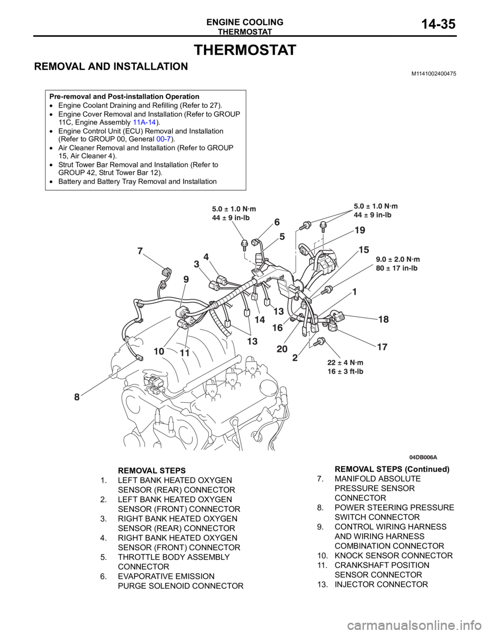
REMOVAL AND INSTALLATIONM1141002400475
Pre-removal and Post-installation Operation
Engine Coolant Draining and Refilling (Refer to 27).
Engine Cover Removal and Installation (Refer to GROUP
11C, Engine Assembly 11A-14).
Engine Control Unit (ECU) Removal and Installation
(Refer to GROUP 00, General 00-7).
Air Cleaner Removal and Installation (Refer to GROUP
15, Air Cleaner 4).
Strut Tower Bar Removal and Installation (Refer to
GROUP 42, Strut Tower Bar 12).
Battery and Battery Tray Removal and Installation
REMOVAL STEPS
1. LEFT BANK HEATED OXYGEN
SENSOR (REAR) CONNECTOR
2. LEFT BANK HEATED OXYGEN
SENSOR (FRONT) CONNECTOR
3. RIGHT BANK HEATED OXYGEN
SENSOR (REAR) CONNECTOR
4. RIGHT BANK HEATED OXYGEN
SENSOR (FRONT) CONNECTOR
5. THROTTLE BODY ASSEMBLY
CONNECTOR
6. EVAPORATIVE EMISSION
PURGE SOLENOID CONNECTOR7. MANIFOLD ABSOLUTE
PRESSURE SENSOR
CONNECTOR
8. POWER STEERING PRESSURE
SWITCH CONNECTOR
9. CONTROL WIRING HARNESS
AND WIRING HARNESS
COMBINATION CONNECTOR
10. KNOCK SENSOR CONNECTOR
11. CRANKSHAFT POSITION
SENSOR CONNECTOR
13. INJECTOR CONNECTORREMOVAL STEPS (Continued)