2005 MITSUBISHI 380 Fuel
[x] Cancel search: FuelPage 1101 of 1500
DOOR
BODY42-34
CIRCUIT BREAKER (INCORPORATED IN THE
POWER WINDOW MOTOR) INSPECTION
M1429001000284
1. Pull the power window switch to the UP position to fully
close the door window glass, and keep pulling the switch for
an additional ten seconds.
2. Release the power window switch from the UP position and
immediately press it to the DOWN position. The condition of
the circuit breaker is good if the door window glass starts to
move downwards within about 60 seconds.
POWER WINDOW CHECKM1429004400214
1. Operate the power window switch of each door to verify that
the power windows operate properly. If they don't, then
troubleshoot as described in GROUP 54B, SWS Diagnosis
P.54B-57.
2. Turn ON the power window lock switch of the power window
main switch. Then operate the passenger's door and rear
door power window sub-switches to ensure that they do not
operate. If they do, replace the power window main switch
(Refer to P.42-39).
CENTRAL DOOR LOCKING SYSTEM
INSPECTION
M1427001100144
Check the following. Troubleshoot if operations malfunction
(Refer to GROUP 54B, SWS Diagnosis P.54B-57).
Insert the key into the driver's key cylinder and turn once to
the unlock side to unlock the driver's door and fuel lid door.
Turn the key once again to the unlock side to unlock all
doors and fuel lid door.
All doors and fuel lid door can be locked using the door lock
switch built into the front power window (main or sub
switch.
Page 1118 of 1500
DOOR
BODY42-51
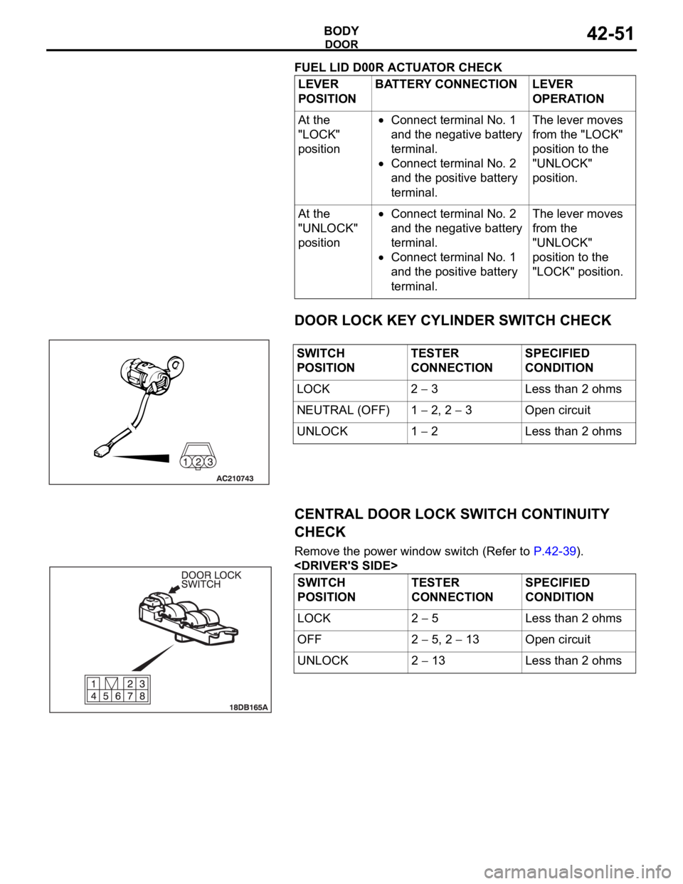
FUEL LID D00R ACTUATOR CHECK
DOOR LOCK KEY CYLINDER SWITCH CHECK
CENTRAL DOOR LOCK SWITCH CONTINUITY
CHECK
Remove the power window switch (Refer to P.42-39).
POSITIONBATTERY CONNECTION LEVER
OPERATION
At the
"LOCK"
position
Connect terminal No. 1
and the negative battery
terminal.
Connect terminal No. 2
and the positive battery
terminal.The lever moves
from the "LOCK"
position to the
"UNLOCK"
position.
At the
"UNLOCK"
position
Connect terminal No. 2
and the negative battery
terminal.
Connect terminal No. 1
and the positive battery
terminal.The lever moves
from the
"UNLOCK"
position to the
"LOCK" position.
SWITCH
POSITIONTESTER
CONNECTIONSPECIFIED
CONDITION
LOCK 2
3 Less than 2 ohms
NEUTRAL (OFF) 1
2, 2 3 Open circuit
UNLOCK 1
2 Less than 2 ohms
SWITCH
POSITIONTESTER
CONNECTIONSPECIFIED
CONDITION
LOCK 2
5 Less than 2 ohms
OFF 2
5, 2 13 Open circuit
UNLOCK 2
13 Less than 2 ohms
Page 1223 of 1500
GENERAL00-2
MAINTENANCE SERVICE . . . . . . . .00-37
1. FUEL SYSTEM (TANK, PIPE LINE AND
CONNECTION, AND FUEL TANK FILLER
TUBE CAP) (CHECK FOR LEAKS) . . . . . . 00-37
2. FUEL HOSES (CHECK CONDITION) . . 00-37
3. AIR CLEANER FILTER (REPLACE). . . . 00-37
4. EVAPORATIVE EMISSION SYSTEM
(EXCEPT EVAPORATIVE EMISSION
CANISTER) (CHECK FOR CLOGGING) . . 00-37
5. SPARK PLUGS (REPLACE). . . . . . . . . . 00-38
7. TIMING BELT (REPLACE) . . . . . . . . . . . 00-38
8. DRIVE BELTS (FOR ALTERNATOR, POWER
STEERING PUMP AND AIR CONDITIONING)
(CHECK) . . . . . . . . . . . . . . . . . . . . . . . . . . . 00-39
9. EXHAUST SYSTEM (CONNECTIONS
PORTION OF MUFFLER, MUFFLER PIPES
AND CONVERTER HEAT SHIELDS) (CHECK
AND SERVICE AS REQUIRED) . . . . . . . . . 00-44
10. ENGINE OIL (CHANGE) . . . . . . . . . . . . 00-4411. ENGINE OIL FILTER (REPLACE) . . . . 00-44
12. TRANSMISSION FLUID . . . . . . . . . . . . 00-45
13. ENGINE COOLANT (CHANGE) . . . . . . 00-47
14. COOLANT HOSES (RADIATOR HOSE,
HEATER HOSE) (INSPECT). . . . . . . . . . . . 00-49
15. DISC BRAKE PADS, ROTORS
(INSPECT FOR WEAR) . . . . . . . . . . . . . . . 00-49
16. BRAKE HOSES (CHECK FOR
DETERIORATION OR LEAKS) . . . . . . . . . . 00-49
17. BALL JOINT AND STEERING LINKAGE
SEALS (INSPECT FOR GREASE LEAKS
AND DAMAGE) . . . . . . . . . . . . . . . . . . . . . . 00-50
18. DRIVE SHAFT BOOTS (INSPECT FOR
GREASE LEAKS AND DAMAGE) . . . . . . . . 00-50
19. SUSPENSION SYSTEM (INSPECT FOR
LOOSENESS AND DAMAGE) . . . . . . . . . . 00-51
20. SRS AIR BAG (INSPECT FOR SRS
SYSTEM). . . . . . . . . . . . . . . . . . . . . . . . . . . 00-51
21. TYRES (ROTATE). . . . . . . . . . . . . . . . . 00-58
Page 1224 of 1500
HOW TO USE THIS MANUAL
GENERAL00-3
HOW TO USE THIS MANUALM1001000100897
MAINTENANCE, REPAIR AND
SERVICING EXPLANATIONS
This manual provides explanations, etc. concerning
procedures for the inspection, maintenance, repair
and servicing of the subject model. Unless otherwise
specified, each service procedure covers all models.
Procedures covering specific models are identified
by the model codes, or similar designation (engine
type, transaxle type, etc). A description of these des-
ignations is covered in this manual under "VEHICLE
IDENTIFICATION."
.
ON-VEHICLE SERVICE
The "ON-VEHICLE SERVICE" section has proce-
dures for performing inspections and adjustments of
particularly important components. These proce-
dures are done with regard to maintenance and ser-
vicing, but other inspections (looseness, play,
cracking, damage, etc.) must also be performed.
.
SERVICE PROCEDURES
The service steps are arranged in numerical order.
Attention to be paid in performing vehicle service are
described in detail in SERVICE POINTS.
DEFINITION OF TERMS
.
STANDARD VALUE
Indicates the value used as the standard for judging
whether or not a part or adjustment is correct.
.
LIMIT
Shows the maximum or minimum value for judging
whether or not a part or adjustment is acceptable.
.
REFERENCE VALUE
Indicates the adjustment value prior to starting the
work (presented in order to facilitate assembly and
adjustment procedures, and so they can be com-
pleted in a shorter time).
.
DANGER, WARNING, AND CAUTION
DANGER, WARNING, and CAUTION call special
attention to a necessary action or to an action that
must be avoided. The differences among DANGER,
WARNING, and CAUTION are as follows:
If a DANGER is not followed, the result is severe
bodily harm or even death.
If a WARNING is not followed, the result could be
bodily injury.
If a CAUTION is not followed, the result could be
damage to the vehicle, vehicle components or
service equipment.
TIGHTENING TORQUE INDICATION
The tightening torque indicates a median and its tol-
erance by a unit of N
m (in-lb.) or Nm (ft.-lb.). For
fasteners with no assigned torque value, refer to
P.00-32.
SPECIAL TOOL NOTE
Only MMC special tool part numbers are called out in
the repair sections of this manual. Please refer to the
special tool cross-reference chart located at the
beginning of each group, for the special tool number
that is available in your market.
ABBREVIATIONS
The following abbreviations are used in this manual
for classification of model types:
A/T:Automatic transaxle, or models equipped with
automatic transaxle.
MPI: Multipoint fuel injection, or engines equipped
with multiport fuel injection.
A/C: Air conditioning.
3.8L engine: 3.8 litre <6G75> engine, or a model
equipped with such an engine.
ABS: Anti-lock Braking System
TCL: Traction Control System
ECU: Electronic Control Unit
V.C.I.: Vehicle Communication Interface
SWS: Simplified Wiring System
CAN: Controller Area Network
M/T: Manual Transmission
SRS: Supplemental Restraint System
Page 1239 of 1500
VEHICLE IDENTIFICATION
GENERAL00-18
VEHICLE IDENTIFICATION
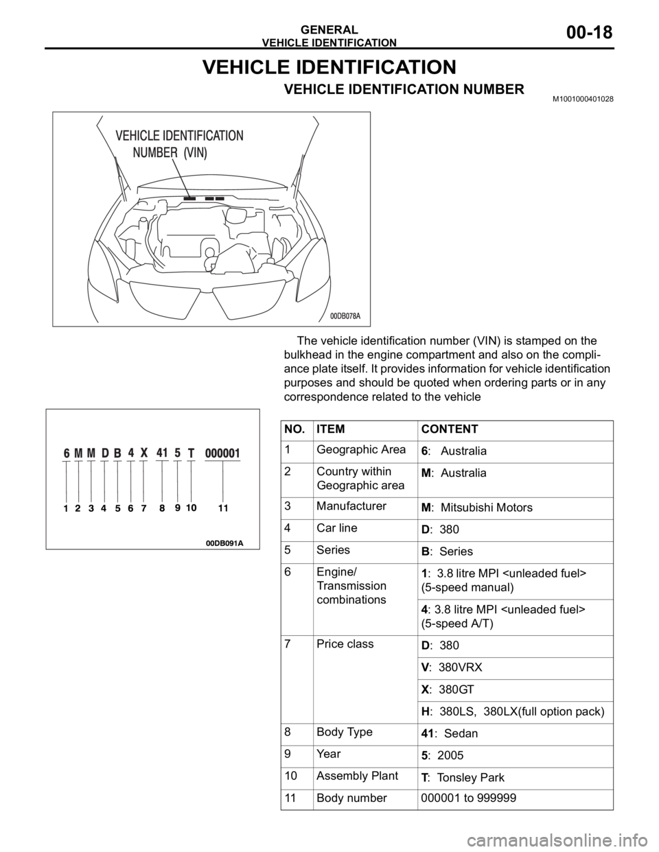
VEHICLE IDENTIFICATION NUMBERM1001000401028
The vehicle identification number (VIN) is stamped on the
bulkhead in the engine compartment and also on the compli-
ance plate itself. It provides information for vehicle identification
purposes and should be quoted when ordering parts or in any
correspondence related to the vehicle
NO. ITEM CONTENT
1 Geographic Area
6: Australia
2 Country within
Geographic areaM: Australia
3 Manufacturer
M: Mitsubishi Motors
4 Car line
D: 380
5Series
B: Series
6 Engine/
Transmission
combinations1: 3.8 litre MPI
(5-speed manual)
4: 3.8 litre MPI
(5-speed A/T)
7Price class
D: 380
V: 380VRX
X: 380GT
H: 380LS, 380LX(full option pack)
8 Body Type
41: Sedan
9Year
5: 2005
10 Assembly Plant
T: Tonsley Park
11 Body number 000001 to 999999
Page 1251 of 1500
TOWING AND HOISTING
GENERAL00-30
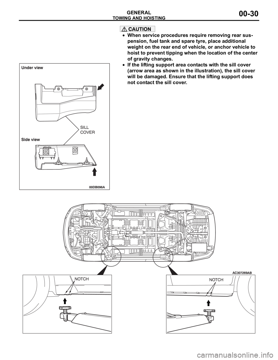
When service procedures require removing rear sus-
pension, fuel tank and spare tyre, place additional
weight on the rear end of vehicle, or anchor vehicle to
hoist to prevent tipping when the location of the center
of gravity changes.
If the lifting support area contacts with the sill cover
(arrow area as shown in the illustration), the sill cover
will be damaged. Ensure that the lifting support does
not contact the sill cover.
Page 1253 of 1500

TIGHTENING TORQUE
GENERAL00-32
TIGHTENING TORQUEM1001001100555
Each torque value in the table is a standard value for
tightening under the following conditions.
1. Bolts, nuts and washers are all made of steel and
plated with zinc.
2. The threads and bearing surface of bolts and
nuts are all in dry condition.
The values in the table are not applicable:1. If toothed washers are inserted.
2. If plastic parts are fastened.
3. If bolts are tightened to plastic or die-cast
inserted nuts.
4. If self-tapping screws or self-locking nuts are
used.
STANDARD BOLT AND NUT TIGHTENING TORQUE Engine Model No. 6G75
Total displacement 3,828cc
Automatic
TransaxleModel No. F5A5A-4-C2Z
Type 5-speed automatic
Manual
Trans.Model No. F 5M51
Type 5-speed manual
Fuel
systemFuel supply system Electronic controlled multipoint fuel injection (MPI) ITEM 380, 380LS, 380LX 380VRX, 380GT
THREAD SIZE STANDARD TIGHTENING TORQUE
NOMINAL BOLT
DIAMETER (mm)PITCH
(mm)HEAD MARK "4" HEAD MARK "7" HEAD MARK "8"
M5 0.8 2.5
0.5 Nm (23 4
in-lb)5.0 1.0 Nm (44 9
in-lb)6.0 1.0 Nm (53 9
in-lb)
M6 1.0 5.0
1.0 Nm (44 9
in-lb)8.5 1.5 Nm (76 13
in-lb)10 2 Nm (89 17
in-lb)
M8 1.25 11
2 Nm (98 17
in-lb)20 4 Nm (15 3 ft-lb) 24 4 Nm (18 3 ft-lb)
M10 1.25 23
4 Nm (17 3 ft-lb) 42 8 Nm (31 6 ft-lb) 53 7 Nm (39 5 ft-lb)
M12 1.25 42
8 Nm (31 6 ft-lb) 80 10 Nm (59 7
ft-lb)93 12 Nm (68 9
ft-lb)
M14 1.5 70
10 Nm (52 7
ft-lb)130 20 Nm (96 15
ft-lb)150 20 Nm ( 111 14
ft-lb)
M16 1.5 105
15 Nm (78 11
ft-lb)195 25 Nm (144 18
ft-lb)230 30 Nm (170 22
ft-lb)
M18 1.5 150
20 Nm ( 111 14
ft-lb)290 40 Nm (214 29
ft-lb)335 45 Nm (247 33
ft-lb)
Page 1255 of 1500
LUBRICATION AND MAINTENANCE
GENERAL00-34
LUBRICATION AND MAINTENANCEM1001001200336
Maintenance and lubrication service recommenda-
tions have been compiled to provide maximum pro-
tection for the vehicle owner's investment against all
reasonable types of driving conditions. Since these
conditions vary with the individual vehicle owner's
driving habits, the area in which the vehicle is oper-
ated and the type of driving to which the vehicle is
subjected, it is necessary to prescribe lubrication and
maintenance service on a time frequency as well as
mileage interval basis.
Oils, lubricants and greases are classified and
graded according to standards recommended by the
Society of Automotive Engineers (SAE) and the Aus-
tralian Petroleum Institute (API).
MAINTENANCE SCHEDULES
For Information on service maintenance refer to the
"Service handbook".
ENGINE OIL
Tests have shown that laboratory animals
develop skin cancer after prolonged contact with
used engine oil. Accordingly, the potential exists
for humans to develop a number of skin disor-
ders, including cancer, from such exposure to
used engine oil. Therefore, when changing
engine oil, be careful not to touch it as much as
possible. Protective clothing and gloves, that
cannot be penetrated by oil, should be worn. The
skin should be thoroughly washed with soap and
water, or use waterless hand cleaner, to remove
any used engine oil. Do not use petrol, thinners,
or solvents.Either of the following engine oils should be used:
1. Engine oil conforming to the ACEA classification:
"For service A1, A2 or A3.
2. Engine oil conforming to the API classification:
"For service SG" or higher.
FUEL USAGE STATEMENT
Using leaded petrol in this car will damage the
catalytic converters and heated oxygen sensors,
and affect the warranty coverage validity.
This vehicle must use unleaded petrol only.
This vehicle has a fuel filler tube which is especially
designed to accept only the smaller-diameter
unleaded petrol dispensing nozzle.
The 3.8L model is designed to operate on unleaded
petrol having an octane rating (DIN 51607) of 90
RON or higher.
.
PETROL CONTAINING ALCOHOL
Some petrol sold at service stations contain alcohol
although they may not be so identified.
Using fuels containing alcohol is not recommended
unless the nature of the blend can be determined as
being satisfactory, as follows.
Gasohol: A mixture of 10% ethanol and 90%
unleaded gasoline may be used in your vehicle. If
driveability problems are experienced as a result of
using gasohol, it is recommended that the vehicle be
operated on petrol.
Methanol: Do not use petrol containing methanol
(wood alcohol). Using this type of alcohol can result
in vehicle performance deterioration and damage
critical parts in the fuel system components. Fuel
system damage and performance problems resulting
from the use of petrol containing methanol may not
be covered by the new vehicle warranty.
MATERIALS ADDED TO FUEL
Indiscriminate use of fuel system cleaning agents
should be avoided. Many materials intended for gum
and varnish removal may contain highly active sol-
vents or similar ingredients that can be harmful to
gasket and diaphragm materials used in fuel system
component parts.