2005 MITSUBISHI 380 Fuel
[x] Cancel search: FuelPage 967 of 1500

Page 968 of 1500

INTAKE MANIFOLD
INTAKE AND EXHAUST15-9
>>C<< FUEL HIGH-PRESSURE HOSE
INSTALLATION
Be careful not to allow any engine oil to enter the fuel
rail.
Be careful not to bend the fuel high-pressure hose as it
is made of plastics.
1. When connecting the fuel high-pressure hose to the fuel rail,
apply a small amount of new engine oil to the O-ring and
then insert the fuel high-pressure hose, being careful not to
damage the O-ring.
2. While turning the fuel high-pressure hose to the left and
right, install it to the fuel rail.
3. Check that the injector turns smoothly. If it does not turn
smoothly, the O-ring may be trapped. Remove the fuel
high-pressure hose and then re-insert it into the fuel rail and
check again.
INSPECTIONM1151003100672
Check the following points; replace the part if a problem is
found.
.
Intake Manifold Check
1. Check for damage or cracking of any part.
2. Clogging of the negative pressure (vacuum) outlet port.
3. Using a straight edge and feeler gauge, check for distortion
of the cylinder head installation surface.
Standard value: 0.15 mm (0.006 inch) or less
Limit: 0.20 mm (0.008 inch)
Page 975 of 1500

SPECIFICATIONS
INTAKE AND EXHAUST15-16
SPECIFICATIONS
FASTENER TIGHTENING SPECIFICATIONSM1151006800506
ITEMSPECIFICATION
Air cleaner
Air cleaner bolt 8.8
1.0 Nm (78 9 in-lb)
Air cleaner bracket bolt and nut 12
2 Nm (102 22 in-lb)
Air cleaner resonator bolt 8.8
1.0 Nm (78 9 in-lb)
Air intake hose clamp bolt 4.0
0.9 Nm (35 8 in-lb)
Airflow sensor nut 8.0
1.0 Nm
Exhaust manifold
Exhaust manifold nut 44
5 Nm (33 3 ft-lb)
Front exhaust pipe bolt 49
9 Nm (37 6 ft-lb)
Exhaust manifold stay, left A bolt M8 19
3 Nm (14 2 ft-lb)
Exhaust manifold stay, left B bolt M10 44
8 Nm (33 5 ft-lb)
Heat protector bolt 14
1 Nm (120 13 in-lb)
Heated oxygen sensor 44
5 Nm (33 3 ft-lb)
Exhaust manifold
Exhaust manifold nut 44
5 Nm (33 3 ft-lb)
Exhaust manifold stay, right A bolt M12 75
10 Nm (55 7 ft-lb)
Exhaust manifold stay, right B bolt M10 44
5 Nm (33 3 ft-lb)
Heat protector bolt 14
1 Nm (120 13 in-lb)
Heated oxygen sensor 44
5 Nm (33 3 ft-lb)
Exhaust pipe and main muffler
Crossmember stay bolt 45
5 Nm (34 3 ft-lb)
Center exhaust pipe nut 49
9 Nm (37 6 ft-lb)
Front floor backbone brace bolt 22
4 Nm (16 3 ft-lb)
Front no.1 exhaust pipe bolt 35
4 Nm (26 3 ft-lb)
Front no.1 exhaust pipe to front no.2 exhaust pipe bolt 49
4 Nm (37 3 ft-lb)
Front no.1 exhaust pipe to right bank exhaust manifold nut 49
9 Nm (37 6 ft-lb)
Front no.1 exhaust pipe to left bank exhaust manifold bolt 49
9 Nm (37 6 ft-lb)
Hanger bolt 12
2 Nm (107 17 in-lb)
Main muffler bolt 49
4 Nm (37 3 ft-lb)
Heat protector bolt 14
1 Nm (120 13 in-lb)
Intake manifold
Control harness clamp bolt 11
1 Nm (98 8 in-lb)
Engine mounting stay bolt 36
6 Nm (27 4 ft-lb)
Fuel rail and injector bolt 12
1 Nm (102 13 in-lb)
Intake manifold bolt 22
1 Nm (16 1 ft-lb)
Timing belt front upper cover bolt M6 11
1 Nm (98 8 in-lb)
M8 14
1 Nm (120 13 in-lb)
Page 1008 of 1500
IGNITION SYSTEM
ENGINE ELECTRICAL16-31
ON-VEHICLE SERVICE
KNOCK CONTROL SYSTEM CHECKM1163001800081
Check the knock sensor circuit if diagnostic trouble code, No.
P0325 is shown.
Refer to GROUP 13B, Multiport Fuel Injection (MPI)
Multiport
Fuel Injection (MPI) Diagnosis
Diagnostic Trouble Code Pro-
cedures
DTC P0325 : Knock Sensor Circuit 13A-346.
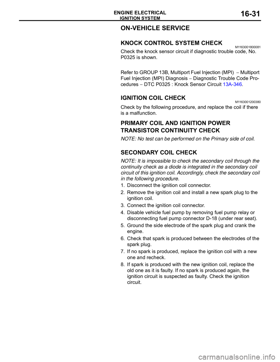
IGNITION COIL CHECK M1163001200380
Check by the following procedure, and replace the coil if there
is a malfunction.
.
PRIMARY COIL AND IGNITION POWER
TRANSISTOR CONTINUITY CHECK
NOTE: No test can be performed on the Primary side of coil.
.
SECONDARY COIL CHECK
NOTE: It is impossible to check the secondary coil through the
continuity check as a diode is integrated in the secondary coil
circuit of this ignition coil. Accordingly, check the secondary coil
in the following procedure.
1. Disconnect the ignition coil connector.
2. Remove the ignition coil and install a new spark plug to the
ignition coil.
3. Connect the ignition coil connector.
4. Disable vehicle fuel pump by removing fuel pump relay or
disconnecting fuel pump connector D-18 (under rear seat).
5. Ground the side electrode of the spark plug and crank the
engine.
6. Check that spark is produced between the electrodes of the
spark plug.
7. If no spark is produced, replace the ignition coil with a new
one and recheck.
8. If spark is produced with the new ignition coil, replace the
old one as it is faulty. If no spark is produced again, the
ignition circuit is suspected as faulty. Check the ignition
circuit.
Page 1009 of 1500
IGNITION SYSTEM
ENGINE ELECTRICAL16-32
SPARK PLUG TESTM1163001500143
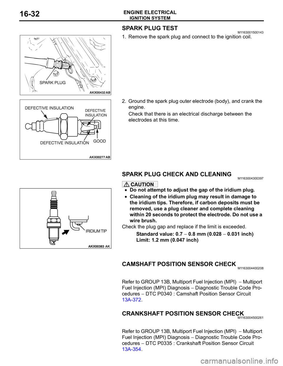
1. Remove the spark plug and connect to the ignition coil.
2. Ground the spark plug outer electrode (body), and crank the
engine.
Check that there is an electrical discharge between the
electrodes at this time.
SPARK PLUG CHECK AND CLEANING M1163004300397
Do not attempt to adjust the gap of the iridium plug.
Cleaning of the iridium plug may result in damage to
the iridium tips. Therefore, if carbon deposits must be
removed, use a plug cleaner and complete cleaning
within 20 seconds to protect the electrode. Do not use a
wire brush.
Check the plug gap and replace if the limit is exceeded.
Standard value: 0.7
0.8 mm (0.028 0.031 inch)
Limit: 1.2 mm (0.047 inch)
CAMSHAFT POSITION SENSOR CHECKM1163004400208
Refer to GROUP 13B, Multiport Fuel Injection (MPI) Multiport
Fuel Injection (MPI) Diagnosis
Diagnostic Trouble Code Pro-
cedures
DTC P0340 : Camshaft Position Sensor Circuit
13A-372.
CRANKSHAFT POSITION SENSOR CHECKM1163004500261
Refer to GROUP 13B, Multiport Fuel Injection (MPI) Multiport
Fuel Injection (MPI) Diagnosis
Diagnostic Trouble Code Pro-
cedures
DTC P0335 : Crankshaft Position Sensor Circuit
13A-354.
Page 1068 of 1500
42-1
GROUP 42
BODY
CONTENTS
HOOD . . . . . . . . . . . . . . . . . . . . .
42-4
BODY DIAGNOSIS . . . . . . . . . . . .
42-4
INTRODUCTION TO HOOD DIAGNOSIS42-4
HOOD DIAGNOSTIC TROUBLESHOOTING
STRATEGY . . . . . . . . . . . . . . . . . . . . . . 42-4
SYMPTOM CHART . . . . . . . . . . . . . . . . 42-4
SYMPTOM PROCEDURES . . . . . . . . . 42-4
ON-VEHICLE SERVICE. . . . . . . . .42-6
ADJUSTMENT OF CLEARANCE
AROUND HOOD . . . . . . . . . . . . . . . . . . 42-6
ALIGNMENT OF HOOD LATCH AND
STRIKER . . . . . . . . . . . . . . . . . . . . . . . . 42-6
ADJUSTMENT OF HOOD HEIGHT . . . 42-7
HOOD . . . . . . . . . . . . . . . . . . . . . . .42-8
REMOVAL AND INSTALLATION . . . . . 42-8
FENDER . . . . . . . . . . . . . . . . . . .42-10
REMOVAL AND INSTALLATION .
42-10
FUEL FILLER LID . . . . . . . . . . .42-11
REMOVAL AND INSTALLATION .
42-11
STRUT TOWER BAR . . . . . . . . 42-12
REMOVAL AND INSTALLATION .
42-12
WINDOW GLASS . . . . . . . . . . . 42-12
GENERAL . . . . . . . . . . . . . . . . . . . .
42-12
WINDOW GLASS DIAGNOSIS . . .42-14
INTRODUCTION TO WINDOW GLASS
DIAGNOSIS . . . . . . . . . . . . . . . . . . . . . . 42-14
WINDOW GLASS DIAGNOSTIC
TROUBLESHOOTING STRATEGY . . . . 42-14
WINDOW GLASS DIAGNOSTIC TROUBLE
SYMPTOM CHART . . . . . . . . . . . . . . . . 42-14
SYMPTOM PROCEDURES . . . . . . . . . . 42-14
SPECIAL TOOL . . . . . . . . . . . . . . .42-14
WINDSHIELD . . . . . . . . . . . . . . . . .42-15
REMOVAL AND INSTALLATION . . . . . . 42-15
REAR WINDOW GLASS . . . . . . . .42-20
REMOVAL AND INSTALLATION . . . . . . 42-20
Continued on next page
Page 1078 of 1500
FUEL FILLER LID
BODY42-11
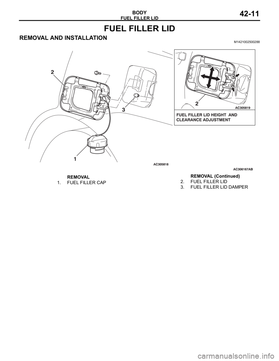
FUEL FILLER LID
REMOVAL AND INSTALLATIONM1421002500288
REMOVAL
1. FUEL FILLER CAP2. FUEL FILLER LID
3. FUEL FILLER LID DAMPERREMOVAL (Continued)
Page 1090 of 1500
DOOR
BODY42-23
DOOR
GENERAL DESCRIPTIONM1423000100246
OPERATION
.
CENTRAL DOOR LOCKING SYSTEM
The central door locking system operates the door
lock actuator to lock or unlock the doors and the fuel
lid door using the door lock switch built into the front
power window (main or sub) switch or key cylinder
built into the driver's side door outside handle. The
system has the following operations and features:
All doors and fuel lid door can be locked using the
door lock switch built into the front power window
(main or sub
Insert the key into the driver's key cylinder and
turn once to the unlock side to unlock the driver's
door and fuel lid door. Turn the key once again to
the unlock side to unlock all doors and fuel lid
door.
The key reminder function automatically unlocks
all doors when door lock operation is performed
and the front doors are opened while the key is
inserted into the ignition switch.
.
POWER WINDOWS
When the power window (main or sub) switch is
operated, the door windows will open or close. This
system has the following operations and features:
A power window lock switch on the power win-
dow main switch prevents the door window glass
from opening/closing with the front passenger's
and rear power window sub switch.
The power window of the door window glass can
be opened/closed for 30 seconds with the timer
function after the ignition switch is turned OFF.
(The timer expires if the front door
opened when the timer is in operation).
The power window main switch contains a
one-touch down switch that will automatically
open the driver's side door window only.
CENTRAL DOOR LOCKING SYSTEM DIAGNOSISM1427000700217
The central door locking system is controlled by the
simplified wiring system (SWS). Refer to GROUP
54B, SWS Diagnosis P.54B-57.
POWER WINDOW DIAGNOSISM1429000700224
The power window is controlled by the simplified wir-
ing system (SWS). Refer to GROUP 54B, SWS
Diagnosis P.54B-57.
DOOR DIAGNOSIS
INTRODUCTION TO GLASS AND DOOR DIAGNOSISM1423007300241
Glass and door faults include water leaks and
improper opening and closing. Causes for these
faults can include faults in the glass, weatherstrip,
drain hole, waterproof film or door installation.
GLASS AND DOOR DIAGNOSTIC TROUBLESHOOTING STRATEGYM1423006700246
Use these steps to plan your diagnostic strategy. If
you follow them carefully, you will be sure that you
have exhausted most of the possible ways to find a
glass and door fault.
1. Gather information from the customer.2. Verify that the condition described by the
customer exists.
3. Find the malfunction by following the Symptom
Chart.
4. Verify malfunction is eliminated.