Page 1177 of 1500
SPECIAL TOOLS
BASIC BRAKE SYSTEM35A-12
STEP 4. Check the wheel bearings for end play.
(1) Remove the brake discs.
(2) Place a dial gauge as shown, and measure the end play
while moving the hub in the axial direction.
Limit: 0.05 mm (0.002 inch)
Q: Does the measured end play exceed the limit?
YES : Replace the faulty hub assembly. Then go to Step 5.
NO : Go to Step 5.
STEP 5. Recheck symptom.
Q: Is the symptom eliminated?
YES : The procedure is complete.
NO : Start over at step 1. If a new symptom surfaces, refer
to the symptom chart.
SPECIAL TOOLSM1351000600360
TOOL TOOL NUMBER AND
NAMESUPERSESSION APPLICATION
MB991568
Push rod adjusting socketGeneral service
toolAdjustment of the brake booster
push rod protrusion amount
MB990964
Brake tool set
A: MB990520
Disc brake piston expanderMB990620-01 or
general service
toolPushing-in of the disc brake
piston
Page 1187 of 1500
ON-VEHICLE SERVICE
BASIC BRAKE SYSTEM35A-22
BRAKE DISC RUN-OUT CHECK AND
CORRECTION
1. Remove the brake assembly, and then hold it with wire.
2. Temporarily install the disc with the hub nut.
3. Place a dial gauge approximately 5 mm (0.2 inch) from the
outer circumference of the brake disc, and measure the
run-out of the disc.
Limit:
: 0.10 mm (0.0039 inch)
: 0.04 mm (0.0016 inch)
4. If the brake disc run-out exceeds the limit, correct it as
follows:
(1) Chalk phase marks on the wheel stud and the brake disc
as shown.
(2) Remove the brake disc. Then place a dial gauge as
shown, and measure the end play while moving the hub
in the axial direction.
Limit: 0.05 mm (0.002 inch)
(3) If the end play exceeds the limit, replace the hub
assembly.
(4) If the end play does not exceed the limit, dephase the
brake disc and secure it. Then recheck the brake disc
run-out.
Page 1262 of 1500
MAINTENANCE SERVICE
GENERAL00-41
WHEN USING THE TENSION GAUGE
Use a belt tension gauge to check that the belt tension is within
the standard value.
Standard value: 490
686 N (110 154 lb)
.
BELT DEFLECTION CHECK
Apply approximately 98 N (22 lb) of force to the middle of the
drive belt between the pulleys (at the place indicated by the
arrow) and check that the amount of deflection in within the
standard value.
Standard value: 8.4
10.7 mm (0.33 0.42 in)
Page 1264 of 1500

MAINTENANCE SERVICE
GENERAL00-43
WHEN USING A TENSION GAUGE
Use a belt tension gauge to check that the belt tension is within
the standard value.
Standard value:
.
BELT DEFLECTION CHECK
Apply approximately 98 N (22 lb) of force to the middle of the
drive belt between the pulleys (at the place indicated by the
arrow) and check that the amount of deflection is within the
standard value.
Standard value:
.if the tension or deflection is outside the standard value, adjust
by the following procedure.
1. Loosen the tensioner pulley lock nut.
2. Adjust the belt tension to the standard value by turning the
adjusting bolt. The tension will increase when turning the
adjusting bolt clockwise, and decrease when turning
counterclockwise.
3. Tighten the lock nut to the specified torque.
Tightening torque: 49
9 Nm (36 7 ft-lb)
4. Tighten the adjusting bolt.
Tightening torque: 5.0
1.0 Nm (44 9 in-lb)
Check after turning the crankshaft one or more rotations
clockwise.
5. Check the belt deflection amount and tension, and readjust
if necessary.
ITEM WHEN
CHECKEDDURING
ADJUSTMENTDURING
REPLACEMENT
Te n s i o n N
(lb)294 490
(66
110)343
441
(77
99)490
686
(110
154)
ITEM WHEN
CHECKEDDURING
ADJUSTMENTDURING
REPLACEMENT
Deflection
(Reference
value) mm
(in)12.3 16.2
(0.48
0.64)13.2
15.1
(0.52
0.59)9.6
12.3
(0.38
0.48)
Page 1420 of 1500

FRONT AXLE DIAGNOSIS
FRONT AXLE26-3
2. Verify that the condition described by the
customer exists.3. Find the malfunction by following the Symptom
Chart.
4. Verify malfunction is eliminated.
SYMPTOM CHARTM1261005700269
SYMPTOM PROCEDURES
INSPECTION PROCEDURE 1: Noise during Wheel Rotation
DIAGNOSIS
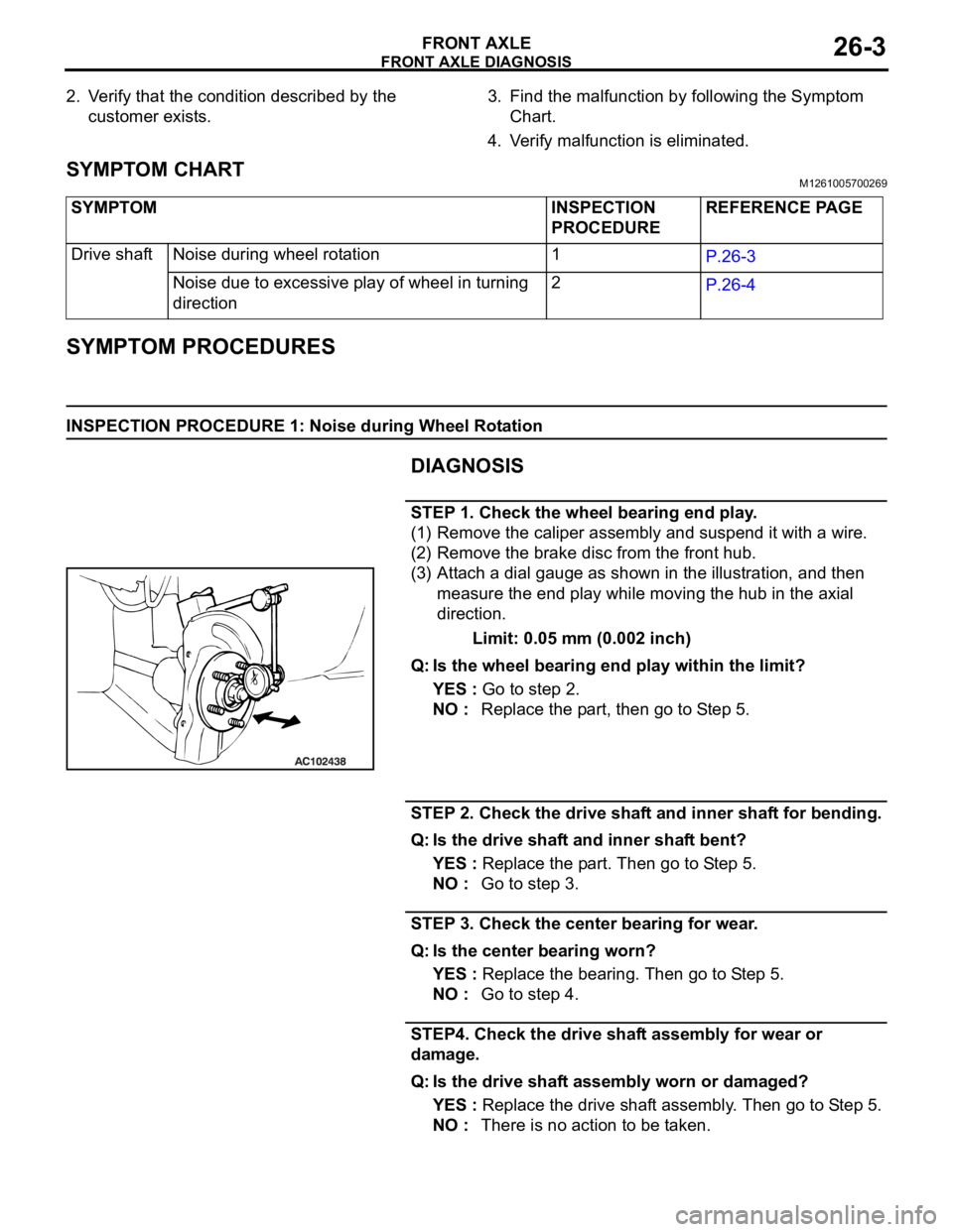
STEP 1. Check the wheel bearing end play.
(1) Remove the caliper assembly and suspend it with a wire.
(2) Remove the brake disc from the front hub.
(3) Attach a dial gauge as shown in the illustration, and then
measure the end play while moving the hub in the axial
direction.
Limit: 0.05 mm (0.002 inch)
Q: Is the wheel bearing end play within the limit?
YES : Go to step 2.
NO : Replace the part, then go to Step 5.
STEP 2. Check the drive shaft and inner shaft for bending.
Q: Is the drive shaft and inner shaft bent?
YES : Replace the part. Then go to Step 5.
NO : Go to step 3.
STEP 3. Check the center bearing for wear.
Q: Is the center bearing worn?
YES : Replace the bearing. Then go to Step 5.
NO : Go to step 4.
STEP4. Check the drive shaft assembly for wear or
damage.
Q: Is the drive shaft assembly worn or damaged?
YES : Replace the drive shaft assembly. Then go to Step 5.
NO : There is no action to be taken. SYMPTOM INSPECTION
PROCEDUREREFERENCE PAGE
Drive shaft Noise during wheel rotation 1
P.26-3
Noise due to excessive play of wheel in turning
direction2
P.26-4
Page 1425 of 1500

ON-VEHICLE SERVICE
FRONT AXLE26-8
ON-VEHICLE SERVICE
WHEEL BEARING END PLAY CHECKM1261000900246
1. Remove the caliper assembly and suspend it with a wire.
2. Remove the brake disc from the front hub.
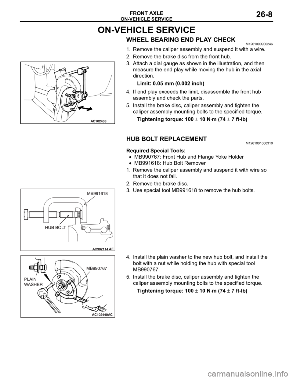
3. Attach a dial gauge as shown in the illustration, and then
measure the end play while moving the hub in the axial
direction.
Limit: 0.05 mm (0.002 inch)
4. If end play exceeds the limit, disassemble the front hub
assembly and check the parts.
5. Install the brake disc, caliper assembly and tighten the
caliper assembly mounting bolts to the specified torque.
Tightening torque: 100
10 Nm (74 7 ft-lb)
HUB BOLT REPLACEMENTM1261001000310
Required Special Tools:
MB990767: Front Hub and Flange Yoke Holder
MB991618: Hub Bolt Remover
1. Remove the caliper assembly and suspend it with wire so
that it does not fall.
2. Remove the brake disc.
3. Use special tool MB991618 to remove the hub bolts.
4. Install the plain washer to the new hub bolt, and install the
bolt with a nut while holding the hub with special tool
MB990767.
5. Install the brake disc, caliper assembly and tighten the
caliper assembly mounting bolts to the specified torque.
Tightening torque: 100
10 Nm (74 7 ft-lb)
Page 1450 of 1500

REAR AXLE DIAGNOSIS
REAR AXLE27-3
SYMPTOM PROCEDURESM1271004400222
INSPECTION PROCEDURE 1: Abnormal Noise
DIAGNOSIS
STEP 1. Check the rear hub assembly installation bolts for
looseness.
Q: Are the rear hub assembly installation bolts loosened?
YES : Tighten the rear hub assembly installation bolts to the
specified torque 73
7 Nm (54 5 ft-lb). Then go to
St e p 4 .
NO : Go to Step 2.
STEP 2. Check the wheel bearing end play.
(1) Remove the caliper assembly, and suspend the caliper
assembly with a wire and remove the brake disc.
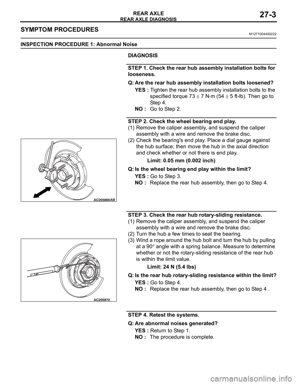
(2) Check the bearing's end play. Place a dial gauge against
the hub surface; then move the hub in the axial direction
and check whether or not there is end play.
Limit: 0.05 mm (0.002 inch)
Q: Is the wheel bearing end play within the limit?
YES : Go to Step 3.
NO : Replace the rear hub assembly, then go to Step 4.
STEP 3. Check the rear hub rotary-sliding resistance.
(1) Remove the caliper assembly, and suspend the caliper
assembly with a wire and remove the brake disc.
(2) Turn the hub a few times to seat the bearing.
(3) Wind a rope around the hub bolt and turn the hub by pulling
at a 90
angle with a spring balance. Measure to determine
whether or not the rotary-sliding resistance of the rear hub
is within the limit value.
Limit: 24 N (5.4 lbs)
Q: Is the rear hub rotary-sliding resistance within the limit?
YES : Go to Step 4.
NO : Replace the rear hub assembly, then go to Step 4 .
STEP 4. Retest the systems.
Q: Are abnormal noises generated?
YES : Return to Step 1.
NO : The procedure is complete.
Page 1451 of 1500

SPECIAL TOOLS
REAR AXLE27-4
SPECIAL TOOLSM1271000600525
ON-VEHICLE SERVICE
WHEEL BEARING END PLAY CHECKM1271000900474
1. Remove the caliper assembly, and suspend the caliper
assembly with a wire and remove the brake disc.
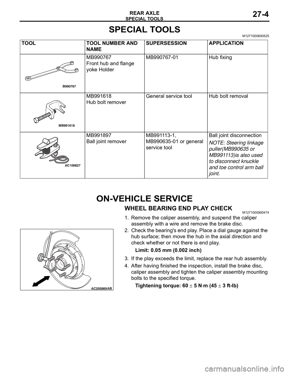
2. Check the bearing's end play. Place a dial gauge against the
hub surface; then move the hub in the axial direction and
check whether or not there is end play.
Limit: 0.05 mm (0.002 inch)
3. If the play exceeds the limit, replace the rear hub assembly.
4. After having finished the inspection, install the brake disc,
caliper assembly and tighten the caliper assembly mounting
bolts to the specified torque.
Tightening torque: 60
5 Nm (45 3 ft-lb) TOOL TOOL NUMBER AND
NAMESUPERSESSION APPLICATION
MB990767
Front hub and flange
yoke HolderMB990767-01 Hub fixing
MB991618
Hub bolt removerGeneral service tool Hub bolt removal
MB991897
Ball joint removerMB991113-1,
MB990635-01 or general
service toolBall joint disconnection
NOTE: Steering linkage
puller(MB990635 or
MB991113)is also used
to disconnect knuckle
and toe control arm ball
joint.