2005 MITSUBISHI 380 service
[x] Cancel search: servicePage 1233 of 1500
HOW TO USE TROUBLESHOOTING/INSPECTION SERVICE POINTS
GENERAL00-12
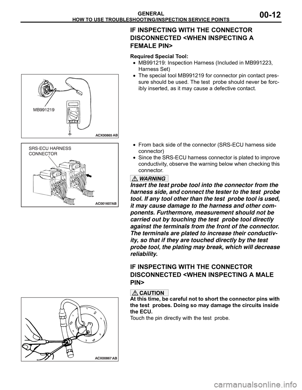
IF INSPECTING WITH THE CONNECTOR
DISCONNECTED
Required Special Tool:
MB991219: Inspection Harness (Included in MB991223,
Harness Set)
The special tool MB991219 for connector pin contact pres-
sure should be used. The test probe should never be forc-
ibly inserted, as it may cause a defective contact.
From back side of the connector (SRS-ECU harness side
connector)
Since the SRS-ECU harness connector is plated to improve
conductivity, observe the warning below when checking this
connector.
Insert the test probe tool into the connector from the
harness side, and connect the tester to the test probe
tool. If any tool other than the test probe tool is used,
it may cause damage to the harness and other com-
ponents. Furthermore, measurement should not be
carried out by touching the test probe tool directly
against the terminals from the front of the connector.
The terminals are plated to increase their conductiv-
ity, so that if they are touched directly by the test
probe tool, the plating may break, which will decrease
reliability.
IF INSPECTING WITH THE CONNECTOR
DISCONNECTED
At this time, be careful not to short the connector pins with
the test probes. Doing so may damage the circuits inside
the ECU.
Touch the pin directly with the test probe.
Page 1234 of 1500
HOW TO USE TROUBLESHOOTING/INSPECTION SERVICE POINTS
GENERAL00-13
CONNECTOR INSPECTION SERVICE POINTSM1001013700060
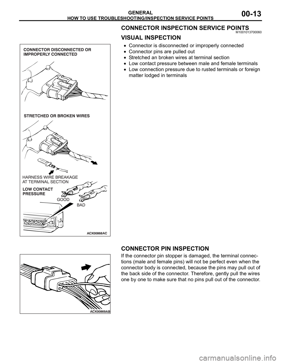
VISUAL INSPECTION
Connector is disconnected or improperly connected
Connector pins are pulled out
Stretched an broken wires at terminal section
Low contact pressure between male and female terminals
Low connection pressure due to rusted terminals or foreign
matter lodged in terminals
.
CONNECTOR PIN INSPECTION
If the connector pin stopper is damaged, the terminal connec-
tions (male and female pins) will not be perfect even when the
connector body is connected, because the pins may pull out of
the back side of the connector. Therefore, gently pull the wires
one by one to make sure that no pins pull out of the connector.
.
Page 1235 of 1500
HOW TO USE TROUBLESHOOTING/INSPECTION SERVICE POINTS
GENERAL00-14
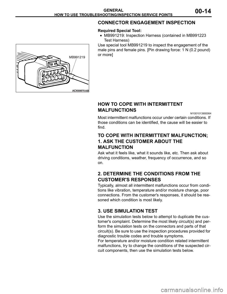
CONNECTOR ENGAGEMENT INSPECTION
Required Special Tool:
MB991219: Inspection Harness (contained in MB991223
Test Harness)
Use special tool MB991219 to inspect the engagement of the
male pins and female pins. [Pin drawing force: 1 N (0.2 pound)
or more]
HOW TO COPE WITH INTERMITTENT
MALFUNCTIONS
M1001013900064
Most intermittent malfunctions occur under certain conditions. If
those conditions can be identified, the cause will be easier to
find.
.
TO COPE WITH INTERMITTENT MALFUNCTION;
1. ASK THE CUSTOMER ABOUT THE
MALFUNCTION
Ask what it feels like, what it sounds like, etc. Then ask about
driving conditions, weather, frequency of occurrence, and so
on.
.
2. DETERMINE THE CONDITIONS FROM THE
CUSTOMER'S RESPONSES
Typically, almost all intermittent malfunctions occur from condi-
tions like vibration, temperature and/or moisture change, poor
connections. From the customer's responses, it should be rea-
soned which condition is most likely.
.
3. USE SIMULATION TEST
Use the simulation tests below to attempt to duplicate the cus-
tomer's complaint. Determine the most likely circuit(s) and per-
form the simulation tests on the connectors and parts of that
circuit(s). Be sure to use the inspection procedures provided for
diagnostic trouble codes and trouble symptoms.
For temperature and/or moisture condition related intermittent
malfunctions, try to change the conditions of the suspected cir-
cuit components, then use the simulation tests below.
.
Page 1236 of 1500
HOW TO USE TROUBLESHOOTING/INSPECTION SERVICE POINTS
GENERAL00-15
4. VERIFY THE INTERMITTENT MALFUNCTION IS
ELIMINATED
Repair the malfunctioning part and try to duplicate the condi-
tion(s) again to verify the intermittent malfunction has been
eliminated.
.
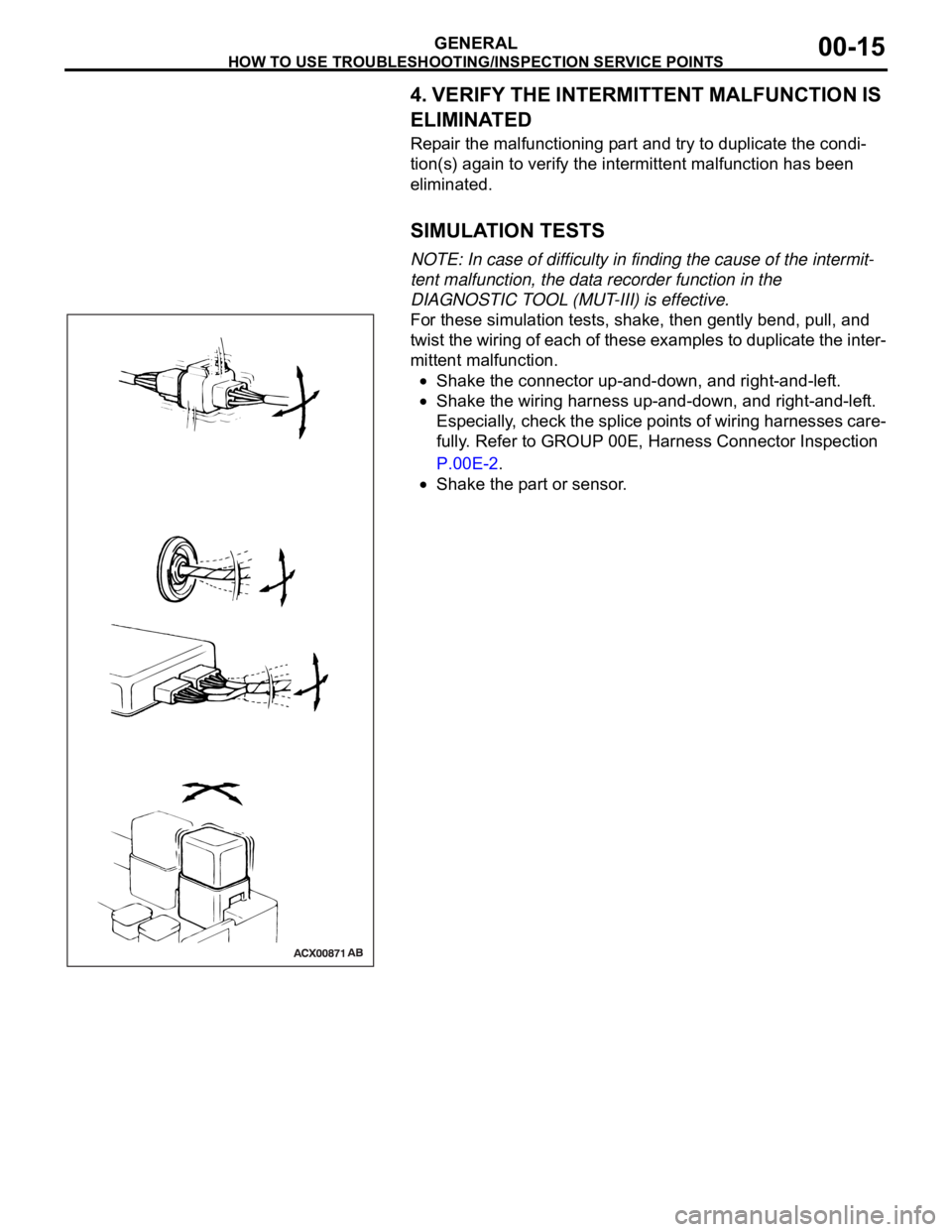
SIMULATION TESTS
NOTE: In case of difficulty in finding the cause of the intermit-
tent malfunction, the data recorder function in the
DIAGNOSTIC TOOL (MUT-III) is effective.
For these simulation tests, shake, then gently bend, pull, and
twist the wiring of each of these examples to duplicate the inter-
mittent malfunction.
Shake the connector up-and-down, and right-and-left.
Shake the wiring harness up-and-down, and right-and-left.
Especially, check the splice points of wiring harnesses care-
fully. Refer to GROUP 00E, Harness Connector Inspection
P.00E-2.
Shake the part or sensor.
Page 1237 of 1500
HOW TO USE TROUBLESHOOTING/INSPECTION SERVICE POINTS
GENERAL00-16
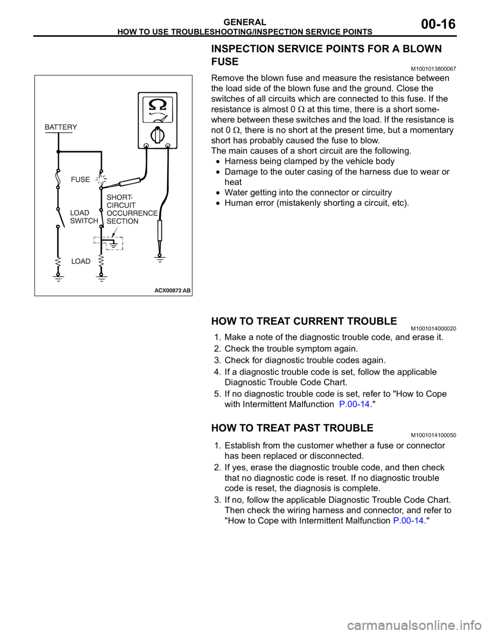
INSPECTION SERVICE POINTS FOR A BLOWN
FUSE
M1001013800067
Remove the blown fuse and measure the resistance between
the load side of the blown fuse and the ground. Close the
switches of all circuits which are connected to this fuse. If the
resistance is almost 0
at this time, there is a short some-
where between these switches and the load. If the resistance is
not 0
, there is no short at the present time, but a momentary
short has probably caused the fuse to blow.
The main causes of a short circuit are the following.
Harness being clamped by the vehicle body
Damage to the outer casing of the harness due to wear or
heat
Water getting into the connector or circuitry
Human error (mistakenly shorting a circuit, etc).
HOW TO TREAT CURRENT TROUBLEM1001014000020
1. Make a note of the diagnostic trouble code, and erase it.
2. Check the trouble symptom again.
3. Check for diagnostic trouble codes again.
4. If a diagnostic trouble code is set, follow the applicable
Diagnostic Trouble Code Chart.
5. If no diagnostic trouble code is set, refer to "How to Cope
with Intermittent Malfunction P.00-14."
HOW TO TREAT PAST TROUBLEM1001014100050
1. Establish from the customer whether a fuse or connector
has been replaced or disconnected.
2. If yes, erase the diagnostic trouble code, and then check
that no diagnostic code is reset. If no diagnostic trouble
code is reset, the diagnosis is complete.
3. If no, follow the applicable Diagnostic Trouble Code Chart.
Then check the wiring harness and connector, and refer to
"How to Cope with Intermittent Malfunction P.00-14."
Page 1243 of 1500
PRECAUTIONS BEFORE SERVICE
GENERAL00-22
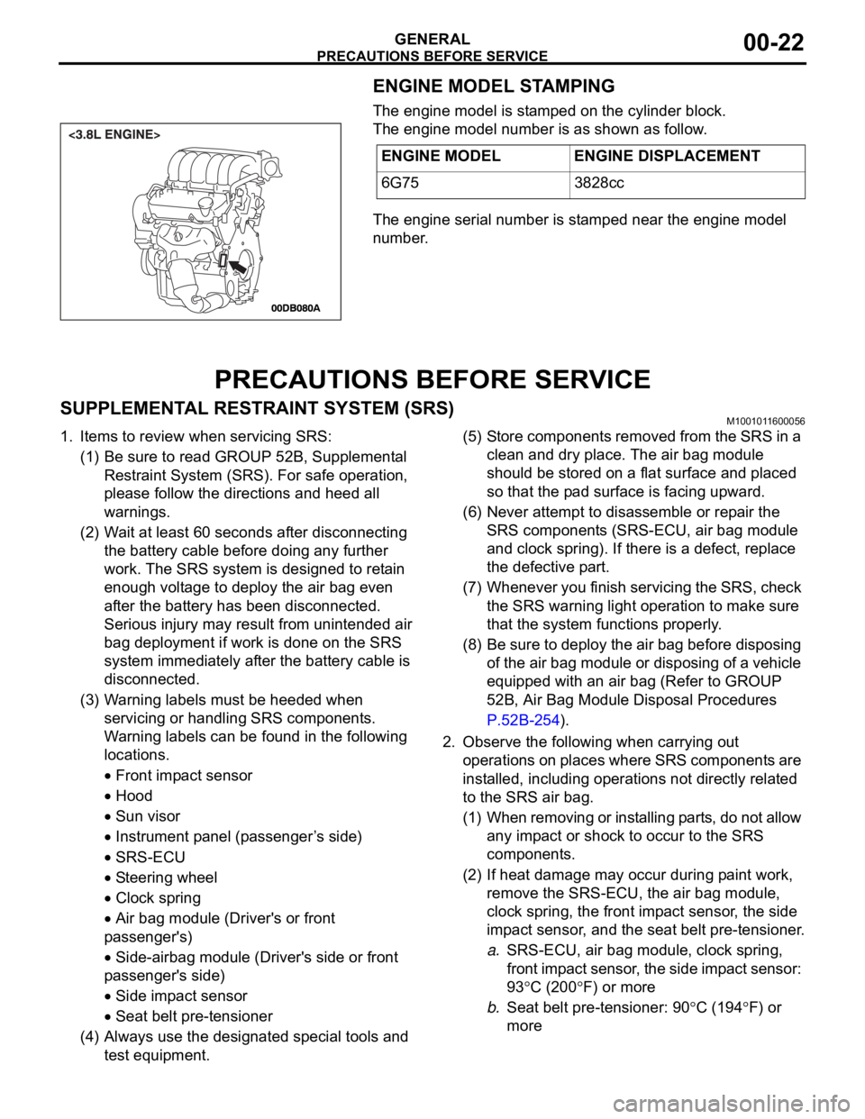
ENGINE MODEL STAMPING
The engine model is stamped on the cylinder block.
The engine model number is as shown as follow.
The engine serial number is stamped near the engine model
number.
PRECAUTIONS BEFORE SERVICE
SUPPLEMENTAL RESTRAINT SYSTEM (SRS)M1001011600056
1. Items to review when servicing SRS:
(1) Be sure to read GROUP 52B, Supplemental
Restraint System (SRS). For safe operation,
please follow the directions and heed all
warnings.
(2) Wait at least 60 seconds after disconnecting
the battery cable before doing any further
work. The SRS system is designed to retain
enough voltage to deploy the air bag even
after the battery has been disconnected.
Serious injury may result from unintended air
bag deployment if work is done on the SRS
system immediately after the battery cable is
disconnected.
(3) Warning labels must be heeded when
servicing or handling SRS components.
Warning labels can be found in the following
locations.
Front impact sensor
Hood
Sun visor
Instrument panel (passenger ’s side)
SRS-ECU
Steering wheel
Clock spring
Air bag module (Driver's or front
passenger's)
Side-airbag module (Driver's side or front
passenger's side)
Side impact sensor
Seat belt pre-tensioner
(4) Always use the designated special tools and
test equipment.(5) Store components removed from the SRS in a
clean and dry place. The air bag module
should be stored on a flat surface and placed
so that the pad surface is facing upward.
(6) Never attempt to disassemble or repair the
SRS components (SRS-ECU, air bag module
and clock spring). If there is a defect, replace
the defective part.
(7) Whenever you finish servicing the SRS, check
the SRS warning light operation to make sure
that the system functions properly.
(8) Be sure to deploy the air bag before disposing
of the air bag module or disposing of a vehicle
equipped with an air bag (Refer to GROUP
52B, Air Bag Module Disposal Procedures
P.52B-254).
2. Observe the following when carrying out
operations on places where SRS components are
installed, including operations not directly related
to the SRS air bag.
(1) When removing or installing parts, do not allow
any impact or shock to occur to the SRS
components.
(2) If heat damage may occur during paint work,
remove the SRS-ECU, the air bag module,
clock spring, the front impact sensor, the side
impact sensor, and the seat belt pre-tensioner.
a.SRS-ECU, air bag module, clock spring,
front impact sensor, the side impact sensor:
93
C (200F) or more
b.Seat belt pre-tensioner: 90
C (194F) or
more ENGINE MODEL ENGINE DISPLACEMENT
6G75 3828cc
Page 1244 of 1500
PRECAUTIONS BEFORE SERVICE
GENERAL00-23
HOW TO PERFORM VEHICLE IDENTIFICATION
NUMBER (VIN) WRITING
M1001011400063
The Vehicle Identification Number (VIN) is stored in the ECU by
the vehicle manufacture. If the VIN to be stored in the ECU is
eliminated fraudulently, the Malfunction Indicator Lamp (Check
Engine Lamp) illuminates and Diagnostic Trouble Code (DTC)
No.P0630 (VIN malfunction) is shown. When the ECU is
replaced, and entry of the VIN necessary due to DTC No.
P0630 (VIN malfunction). Enter the VIN in accordance with the
procedure as follows:
.
WRITING PROCEDURE
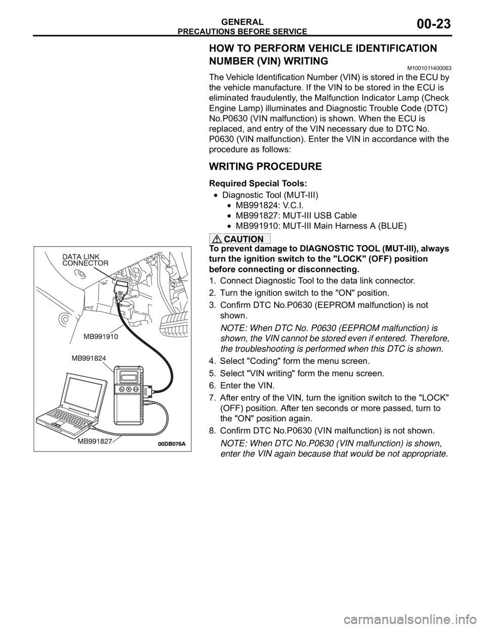
Required Special Tools:
Diagnostic Tool (MUT-III)
MB991824: V.C.I.
MB991827: MUT-III USB Cable
MB991910: MUT-III Main Harness A (BLUE)
To prevent damage to DIAGNOSTIC TOOL (MUT-III), always
turn the ignition switch to the "LOCK" (OFF) position
before connecting or disconnecting.
1. Connect Diagnostic Tool to the data link connector.
2. Turn the ignition switch to the "ON" position.
3. Confirm DTC No.P0630 (EEPROM malfunction) is not
shown.
NOTE: When DTC No. P0630 (EEPROM malfunction) is
shown, the VIN cannot be stored even if entered. Therefore,
the troubleshooting is performed when this DTC is shown.
4. Select "Coding" form the menu screen.
5. Select "VIN writing" form the menu screen.
6. Enter the VIN.
7. After entry of the VIN, turn the ignition switch to the "LOCK"
(OFF) position. After ten seconds or more passed, turn to
the "ON" position again.
8. Confirm DTC No.P0630 (VIN malfunction) is not shown.
NOTE: When DTC No.P0630 (VIN malfunction) is shown,
enter the VIN again because that would be not appropriate.
Page 1245 of 1500
PRECAUTIONS BEFORE SERVICE
GENERAL00-24
SERVICING ELECTRICAL SYSTEMM1001011900057
Battery posts, terminals and related accessories con-
tain lead and lead compounds. WASH HANDS AFTER
HANDLING.
1. Note the following before proceeding with working on the
electrical system.
Never perform unauthorized modifications to any electrical
device or wiring. Such modifications might lead to a vehicle
malfunction, over-capacity or short-circuit that could result in
a fire in the vehicle.
Before connecting or disconnecting the negative bat-
tery cable, be sure to turn the ignition switch to the
"LOCK" (OFF) position and turn off the lights (If this is
not done, there is the possibility of semiconductor
parts being damaged).
After completion of the work (and the negative battery
terminals is connected), warm up the engine and allow
it to idle for approximately 10 minutes under the condi-
tions described below in order to stabilize engine con-
trol conditions, and then check to be sure that the idle
is satisfactory.
Engine coolant temperature: 85 to 95C (185 to
203
F)
Lights and all accessories: OFF
Transaxle: "N" or "P" position
Steering wheel: straight-forward position
2. When servicing the electrical system, disconnect the
negative cable terminal from the battery.
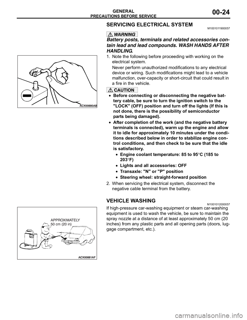
VEHICLE WASHINGM1001012000057
If high-pressure car-washing equipment or steam car-washing
equipment is used to wash the vehicle, be sure to maintain the
spray nozzle at a distance of at least approximately 50 cm (20
inches) from any plastic parts and all opening parts (doors, lug-
gage compartment, etc.).