2005 MITSUBISHI 380 automatic transmission
[x] Cancel search: automatic transmissionPage 1224 of 1500
HOW TO USE THIS MANUAL
GENERAL00-3
HOW TO USE THIS MANUALM1001000100897
MAINTENANCE, REPAIR AND
SERVICING EXPLANATIONS
This manual provides explanations, etc. concerning
procedures for the inspection, maintenance, repair
and servicing of the subject model. Unless otherwise
specified, each service procedure covers all models.
Procedures covering specific models are identified
by the model codes, or similar designation (engine
type, transaxle type, etc). A description of these des-
ignations is covered in this manual under "VEHICLE
IDENTIFICATION."
.
ON-VEHICLE SERVICE
The "ON-VEHICLE SERVICE" section has proce-
dures for performing inspections and adjustments of
particularly important components. These proce-
dures are done with regard to maintenance and ser-
vicing, but other inspections (looseness, play,
cracking, damage, etc.) must also be performed.
.
SERVICE PROCEDURES
The service steps are arranged in numerical order.
Attention to be paid in performing vehicle service are
described in detail in SERVICE POINTS.
DEFINITION OF TERMS
.
STANDARD VALUE
Indicates the value used as the standard for judging
whether or not a part or adjustment is correct.
.
LIMIT
Shows the maximum or minimum value for judging
whether or not a part or adjustment is acceptable.
.
REFERENCE VALUE
Indicates the adjustment value prior to starting the
work (presented in order to facilitate assembly and
adjustment procedures, and so they can be com-
pleted in a shorter time).
.
DANGER, WARNING, AND CAUTION
DANGER, WARNING, and CAUTION call special
attention to a necessary action or to an action that
must be avoided. The differences among DANGER,
WARNING, and CAUTION are as follows:
If a DANGER is not followed, the result is severe
bodily harm or even death.
If a WARNING is not followed, the result could be
bodily injury.
If a CAUTION is not followed, the result could be
damage to the vehicle, vehicle components or
service equipment.
TIGHTENING TORQUE INDICATION
The tightening torque indicates a median and its tol-
erance by a unit of N
m (in-lb.) or Nm (ft.-lb.). For
fasteners with no assigned torque value, refer to
P.00-32.
SPECIAL TOOL NOTE
Only MMC special tool part numbers are called out in
the repair sections of this manual. Please refer to the
special tool cross-reference chart located at the
beginning of each group, for the special tool number
that is available in your market.
ABBREVIATIONS
The following abbreviations are used in this manual
for classification of model types:
A/T:Automatic transaxle, or models equipped with
automatic transaxle.
MPI: Multipoint fuel injection, or engines equipped
with multiport fuel injection.
A/C: Air conditioning.
3.8L engine: 3.8 litre <6G75> engine, or a model
equipped with such an engine.
ABS: Anti-lock Braking System
TCL: Traction Control System
ECU: Electronic Control Unit
V.C.I.: Vehicle Communication Interface
SWS: Simplified Wiring System
CAN: Controller Area Network
M/T: Manual Transmission
SRS: Supplemental Restraint System
Page 1248 of 1500
TOWING AND HOISTING
GENERAL00-27
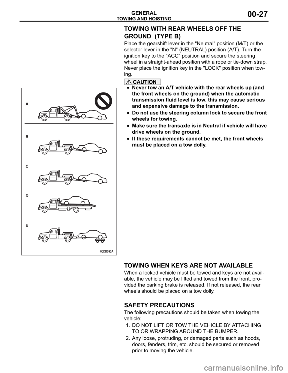
TOWING WITH REAR WHEELS OFF THE
GROUND (TYPE B)
Place the gearshift lever in the "Neutral" position (M/T) or the
selector lever in the "N" (NEUTRAL) position (A/T). Turn the
ignition key to the "ACC" position and secure the steering
wheel in a straight-ahead position with a rope or tie-down strap.
Never place the ignition key in the "LOCK" position when tow-
ing.
Never tow an A/T vehicle with the rear wheels up (and
the front wheels on the ground) when the automatic
transmission fluid level is low. this may cause serious
and expensive damage to the transmission.
Do not use the steering column lock to secure the front
wheels for towing.
Make sure the transaxle is in Neutral if vehicle will have
drive wheels on the ground.
If these requirements cannot be met, the front wheels
must be placed on a tow dolly.
.
TOWING WHEN KEYS ARE NOT AVAILABLE
When a locked vehicle must be towed and keys are not avail-
able, the vehicle may be lifted and towed from the front, pro-
vided the parking brake is released. If not released, the rear
wheels should be placed on a tow dolly.
.
SAFETY PRECAUTIONS
The following precautions should be taken when towing the
vehicle:
1. DO NOT LIFT OR TOW THE VEHICLE BY ATTACHING
TO OR WRAPPING AROUND THE BUMPER.
2. Any loose, protruding, or damaged parts such as hoods,
doors, fenders, trim, etc. should be secured or removed
prior to moving the vehicle.
Page 1256 of 1500

RECOMMENDED LUBRICANTS AND LUBRICANT CAPACITIES TABLE
GENERAL00-35
RECOMMENDED LUBRICANTS AND LUBRICANT
CAPACITIES TABLE
M1001001300504
RECOMMENDED LUBRICANTS
LUBRICANT CAPACITY TABLE
<3.8L ENGINE>LUBRICANT SPECIFICATION
Engine oil Engine oils conforming to ACEA A1, A2 or A3 and
AP1 SG or higher
AutomaticTransmission fluid Genuine Mitsubishi Motors ATF-SP III
Manual Transmission fluid Genuine Mitsubishi Motors MTF
Power steering fluid ATF DEXRON III or DEXRON II
Brakes fluid Conforming to DOT 3 or DOT 4
Engine coolant Genuine Mitsubishi Motors coolant
Refrigerant (air conditioning) HFC-134a
DESCRIPTION SPECIFICATION
Engine oil (Litres) Oil pan (excluding oil filter) 4.0
Oil filter 0.3
Engine coolant (Litres) 8.7
Automatic Transmission fluid (Litres) 8.4
Manual Transmission fluid (Litres) 2.8
Power steering fluid (Litres) 1.2
Fuel tank (Litres) 67.0
Washer fluid (Litres) 5.0
Refrigerant (air conditioning) (grams) 435g - 475g
Page 1268 of 1500
MAINTENANCE SERVICE
GENERAL00-47
6. Securely insert the dipstick.
NOTE: The transmission fluid should always be replaced
under the following conditions:
.
When troubleshooting the transaxle.
When overhauling the transaxle.
When the transmission fluid is noticeably dirty or burnt
(driving under severe conditions).
TRANSMISSION FLUID CHANGE
Refer to GROUP 23A, Automatic Transmission - On-vehicle
Service P.23A-296.
12. ENGINE COOLANT (CHANGE)M1001003100357
Check the cooling system parts such as the radiator, heater
and oil cooler hoses, thermostat and their connections for leak-
age and damage.
.
CHANGING COOLANT
1. Set the temperature control knob to the "HOT" position.
2. Run the engine until the engine coolant warms, and then
stop the engine.
When removing the radiator cap, use care to avoid
contact with hot coolant or steam. Place a shop towel
over the cap and turn the cap counterclockwise a lit-
tle to let the pressure escape through the vinyl tube.
After relieving the steam pressure, remove the cap by
slowly turning it counterclockwise.
3. Drain the water from the radiator, heater core and engine
after unplugging the radiator drain plug and removing the
radiator cap.
Page 1406 of 1500
AUTO-CRUISE CONTROL
ENGINE AND EMISSION CONTROL17-75
AUTO-CRUISE CONTROL
REMOVAL AND INSTALLATIONM1172001400467
Before removal of the air bag module, refer to GROUP 52B, SRS Service Precautions
P.52B-16 and GROUP 52B, Air Bag Module and Clock Spring P.52B-237.
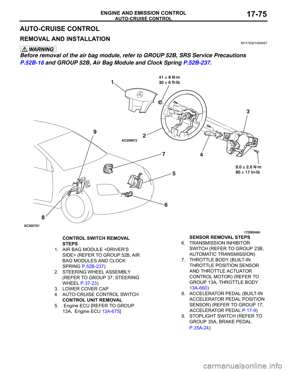
CONTROL SWITCH REMOVAL
STEPS
1. AIR BAG MODULE
BAG MODULES AND CLOCK
SPRING P.52B-237)
2. STEERING WHEEL ASSEMBLY
(REFER TO GROUP 37, STEERING
WHEEL P.37-23)
3. LOWER COVER CAP
4. AUTO-CRUISE CONTROL SWITCH
CONTROL UNIT REMOVAL
5. Engine ECU [REFER TO GROUP
13A, Engine ECU 13A-675] SENSOR REMOVAL STEPS
6. TRANSMISSION INHIBITOR
SWITCH (REFER TO GROUP 23B,
AUTOMATIC TRANSMISSION)
7. THROTTLE BODY (BUILT-IN
THROTTLE POSITION SENSOR
AND THROTTLE ACTUATOR
CONTROL MOTOR) (REFER TO
GROUP 13A, THROTTLE BODY
13A-660)
8. ACCELERATOR PEDAL (BUILT-IN
ACCELERATOR PEDAL POSITION
SENSOR) (REFER TO GROUP 17,
ACCELERATOR PEDAL P.17-9)
9. STOPLIGHT SWITCH (REFER TO
GROUP 35A, BRAKE PEDAL
P.35A-24)
Page 1460 of 1500
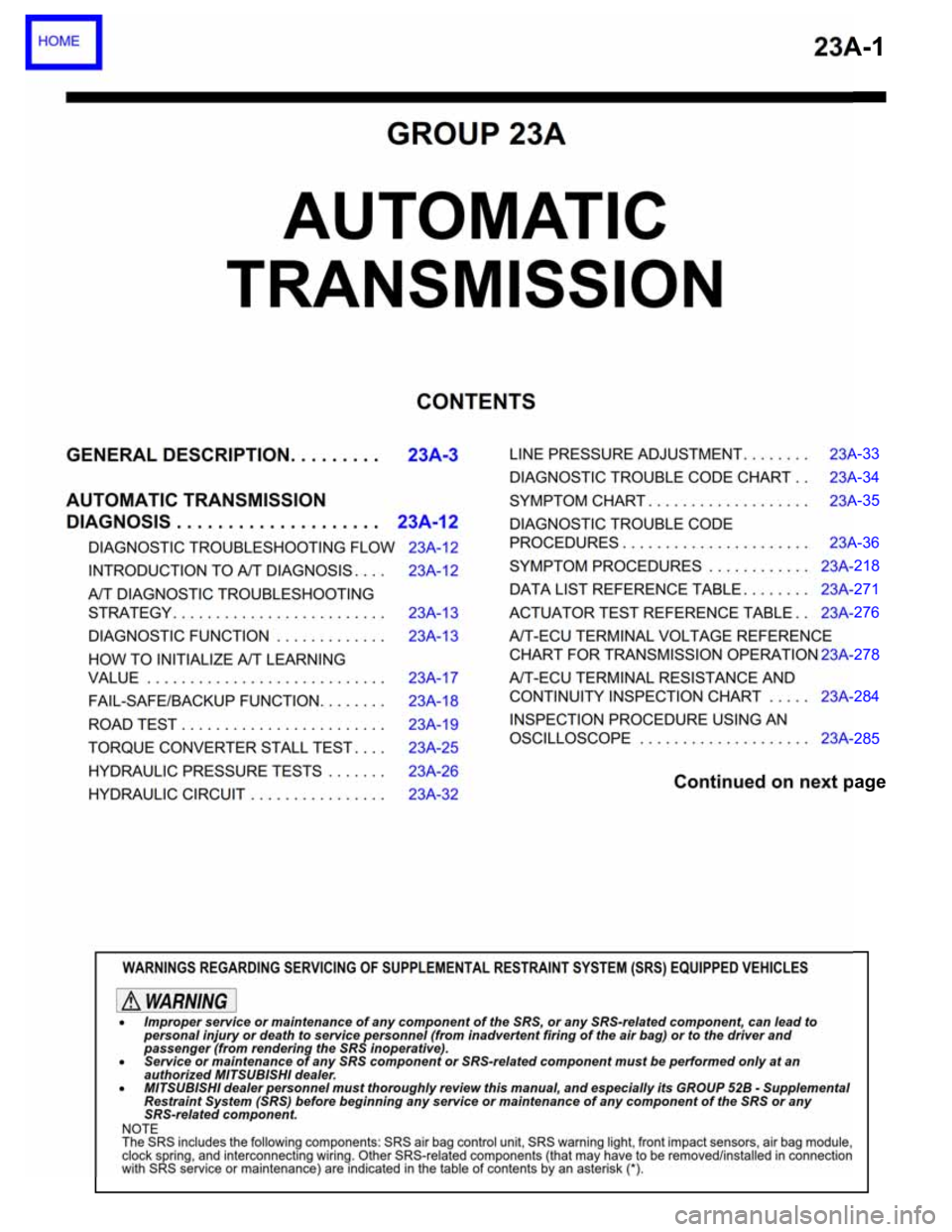
23A-1
GROUP 23A
AUTOMATIC
TRANSMISSION
CONTENTS
GENERAL DESCRIPTION. . . . . . . . .23A-3
AUTOMATIC TRANSMISSION
DIAGNOSIS . . . . . . . . . . . . . . . . . . . .23A-12
DIAGNOSTIC TROUBLESHOOTING FLOW23A-12
INTRODUCTION TO A/T DIAGNOSIS . . . . 23A-12
A/T DIAGNOSTIC TROUBLESHOOTING
STRATEGY . . . . . . . . . . . . . . . . . . . . . . . . . 23A-13
DIAGNOSTIC FUNCTION . . . . . . . . . . . . . 23A-13
HOW TO INITIALIZE A/T LEARNING
VALUE . . . . . . . . . . . . . . . . . . . . . . . . . . . . 23A-17
FAIL-SAFE/BACKUP FUNCTION. . . . . . . . 23A-18
ROAD TEST . . . . . . . . . . . . . . . . . . . . . . . . 23A-19
TORQUE CONVERTER STALL TEST . . . . 23A-25
HYDRAULIC PRESSURE TESTS . . . . . . . 23A-26
HYDRAULIC CIRCUIT . . . . . . . . . . . . . . . . 23A-32LINE PRESSURE ADJUSTMENT . . . . . . . . 23A-33
DIAGNOSTIC TROUBLE CODE CHART . . 23A-34
SYMPTOM CHART . . . . . . . . . . . . . . . . . . . 23A-35
DIAGNOSTIC TROUBLE CODE
PROCEDURES . . . . . . . . . . . . . . . . . . . . . . 23A-36
SYMPTOM PROCEDURES . . . . . . . . . . . . 23A-218
DATA LIST REFERENCE TABLE . . . . . . . . 23A-271
ACTUATOR TEST REFERENCE TABLE . . 23A-276
A/T-ECU TERMINAL VOLTAGE REFERENCE
CHART FOR TRANSMISSION OPERATION23A-278
A/T-ECU TERMINAL RESISTANCE AND
CONTINUITY INSPECTION CHART . . . . . 23A-284
INSPECTION PROCEDURE USING AN
OSCILLOSCOPE . . . . . . . . . . . . . . . . . . . . 23A-285
Continued on next page
WARNINGS REGARDING SERVICING OF SUPPLEMENTAL RESTRAINT SYSTEM (SRS) EQUIPPED VEHICLES
Page 1461 of 1500
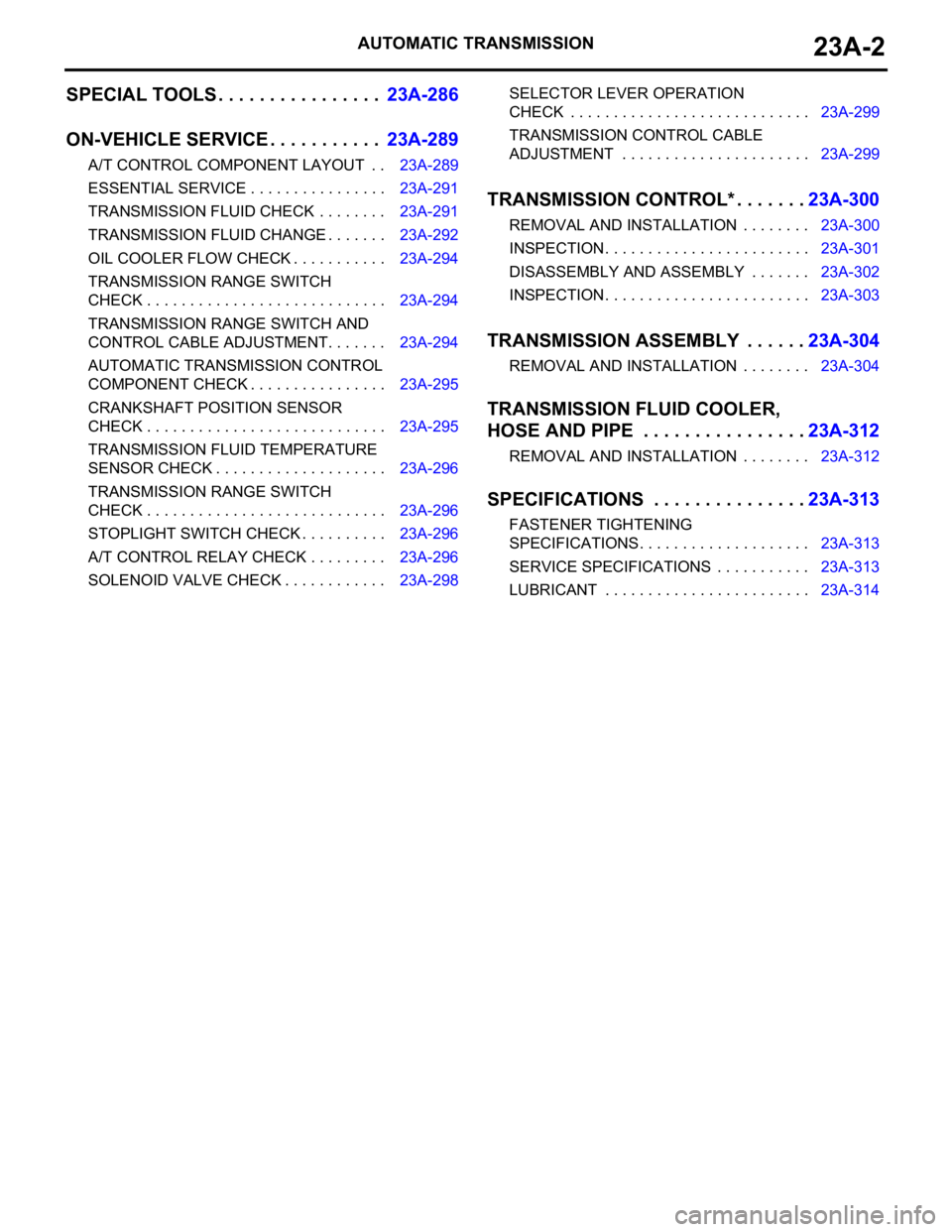
AUTOMATIC TRANSMISSION23A-2
SPECIAL TOOLS . . . . . . . . . . . . . . . .23A-286
ON-VEHICLE SERVICE. . . . . . . . . . .23A-289
A/T CONTROL COMPONENT LAYOUT . . 23A-289
ESSENTIAL SERVICE . . . . . . . . . . . . . . . . 23A-291
TRANSMISSION FLUID CHECK . . . . . . . . 23A-291
TRANSMISSION FLUID CHANGE . . . . . . . 23A-292
OIL COOLER FLOW CHECK . . . . . . . . . . . 23A-294
TRANSMISSION RANGE SWITCH
CHECK . . . . . . . . . . . . . . . . . . . . . . . . . . . . 23A-294
TRANSMISSION RANGE SWITCH AND
CONTROL CABLE ADJUSTMENT. . . . . . . 23A-294
AUTOMATIC TRANSMISSION CONTROL
COMPONENT CHECK . . . . . . . . . . . . . . . . 23A-295
CRANKSHAFT POSITION SENSOR
CHECK . . . . . . . . . . . . . . . . . . . . . . . . . . . . 23A-295
TRANSMISSION FLUID TEMPERATURE
SENSOR CHECK . . . . . . . . . . . . . . . . . . . . 23A-296
TRANSMISSION RANGE SWITCH
CHECK . . . . . . . . . . . . . . . . . . . . . . . . . . . . 23A-296
STOPLIGHT SWITCH CHECK . . . . . . . . . . 23A-296
A/T CONTROL RELAY CHECK . . . . . . . . . 23A-296
SOLENOID VALVE CHECK . . . . . . . . . . . . 23A-298SELECTOR LEVER OPERATION
CHECK . . . . . . . . . . . . . . . . . . . . . . . . . . . . 23A-299
TRANSMISSION CONTROL CABLE
ADJUSTMENT . . . . . . . . . . . . . . . . . . . . . . 23A-299
TRANSMISSION CONTROL* . . . . . . .23A-300
REMOVAL AND INSTALLATION . . . . . . . . 23A-300
INSPECTION. . . . . . . . . . . . . . . . . . . . . . . . 23A-301
DISASSEMBLY AND ASSEMBLY . . . . . . . 23A-302
INSPECTION. . . . . . . . . . . . . . . . . . . . . . . . 23A-303
TRANSMISSION ASSEMBLY . . . . . .23A-304
REMOVAL AND INSTALLATION . . . . . . . . 23A-304
TRANSMISSION FLUID COOLER,
HOSE AND PIPE . . . . . . . . . . . . . . . .23A-312
REMOVAL AND INSTALLATION . . . . . . . . 23A-312
SPECIFICATIONS . . . . . . . . . . . . . . .23A-313
FASTENER TIGHTENING
SPECIFICATIONS. . . . . . . . . . . . . . . . . . . . 23A-313
SERVICE SPECIFICATIONS . . . . . . . . . . . 23A-313
LUBRICANT . . . . . . . . . . . . . . . . . . . . . . . . 23A-314
Page 1462 of 1500

GENERAL DESCRIPTION
AUTOMATIC TRANSMISSION23A-3
GENERAL DESCRIPTIONM1231000100366
ITEM SPECIFICATION
Transmission modelF5A5A-4-C5Z
Engine model 6G75-S4-MP
Torque converter Type 3-element, 1-stage, 2-phase type
Lock-up Provided
Stall torque ratio 1.71
Transmission type5 forward speeds, 1 reverse speed, fully automatic
Transmission gear
ratio1st 3.789
2nd 2.162
3rd 1.421
4th 1.000
5th 0.686
Reverse 3.117
Final reduction ratio (Differential gear ratio) 3.325
Clutch Multi-disc type 4 sets
Brake Multi-disc type 2 sets, band type 1 set
Manual control system P-R-N-D (4 position) + Sport mode (up, down)
Shift pattern control Electronic control
Hydraulic control during shifting Electronic control (Each clutch hydraulically independently
controlled)
Torque converter clutch control Electronic control
Transmission fluid Specified lubricants MITSUBISHI ELC4-SP III
Quantity (litres) 8.4