Page 1487 of 1500

AUTOMATIC TRANSMISSION DIAGNOSIS
AUTOMATIC TRANSMISSION23A-28
STANDARD HYDRAULIC PRESSURE TABLE
NOTE: When the torque converter pressure is measured, the engine speed should be 1,500 r/min or less.
HYDRAULIC PRESSURE TEST DIAGNOSIS TABLE
MEASUREMENT
CONDITIONSSTANDARD HYDRAULIC PRESSURE kPa
SELECT-
OR
LEVER
POS’N SHIFT
RANGE
POSITIO
NENGINE
SPEED
(r/min)UNDERDRIVE
CLUTCH
PRESSURE
[UD]REVERSE
CLUTCH
PRESSURE
[RV]OVERDRIVE
CLUTCH
PRESSURE
[OD]DIRECT
CLUTCH
PRESSURE
[DIR]LOW-
REVERSE
BRAKE
PRESSURE
[LR]SECOND
BRAKE
PRESSURE
[2ND]TORQUE
CONVERTER
PRESSURE
[DR]
P2,500260 360260 360
R Rev. 2,500
12701770 12701770 500 730
N
2,500260 360 220 360
Spo rt
mode1st 2,500 980
1050 980 1050 500 730
2nd 2,500 980
1050 980 1050 500 730
3rd 2,500 780
900 780 900 450 720
4th 2,500 780
900 780 900 780 880 450 720
5th 2,500
780 900 780 880 780 880 450 720
SYMPTOM PROBABLE CAUSE
All hydraulic pressures are high. Malfunction of the regulator valve
All hydraulic pressures are low. Malfunction of the oil pump
Clogged internal oil filter
Clogged oil cooler
Malfunction of the regulator valve
Malfunction of the relief valve
Incorrect valve body installation
Improperly installed solenoid valves
Damaged solenoid valve O-rings
Hydraulic pressure is abnormal
in reverse gear only.Malfunction of the regulator valve
Clogged orifice
Incorrect valve body installation
Hydraulic pressure is abnormal
in 3rd or 4th gear only.Malfunction of the overdrive solenoid valve
Malfunction of the overdrive pressure control valve
Malfunction of the regulator valve
Malfunction of the switch valve
Clogged orifice
Incorrect valve body installation
Page 1488 of 1500

AUTOMATIC TRANSMISSION DIAGNOSIS
AUTOMATIC TRANSMISSION23A-29
Only underdrive clutch hydraulic
pressure is abnormal.Malfunction of the oil seal K
Malfunction of the oil seal L
Malfunction of the oil seal M
Malfunction of the underdrive solenoid valve
Malfunction of the underdrive pressure control valve
Malfunction of the check ball
Clogged orifice
Incorrect valve body installation
Malfunction of the accumulator for underdrive clutch
Only reverse clutch hydraulic
pressure is abnormal.Malfunction of the oil seal A
Malfunction of the oil seal B
Malfunction of the oil seal C
Clogged orifice
Incorrect valve body installation
Only overdrive clutch hydraulic
pressure is abnormal.Malfunction of the oil seal D
Malfunction of the oil seal E
Malfunction of the oil seal F
Malfunction of the overdrive solenoid valve
Malfunction of the overdrive pressure control valve
Malfunction of the check ball
Clogged orifice
Incorrect valve body installation
Malfunction of the accumulator for overdrive clutch
Only direct clutch hydraulic
pressure is abnormal.Malfunction of the oil seal R, S or T
Malfunction of the low-reverse solenoid valve(also used for direct clutch)
Malfunction of the low-reverse pressure control valve
Malfunction of the switch valve
Malfunction of the fail safe valve C
Clogged orifice
Incorrect valve body installation
Only low-reverse brake
hydraulic pressure is abnormal.Malfunction of the oil seal I
Malfunction of the oil seal J
Malfunction of the low-reverse solenoid valve
Malfunction of the low-reverse pressure control valve
Malfunction of the switch valve
Malfunction of the fail safe valve A
Malfunction of all the check balls
Clogged orifice
Incorrect valve body installation
Malfunction of the accumulator for low-reverse brake SYMPTOM PROBABLE CAUSE
Page 1489 of 1500

AUTOMATIC TRANSMISSION DIAGNOSIS
AUTOMATIC TRANSMISSION23A-30
Only second brake hydraulic
pressure is abnormal.Malfunction of the oil seal G
Malfunction of the oil seal H
Malfunction of the oil seal O
Malfunction of the second solenoid valve
Malfunction of the second pressure control valve
Malfunction of the fail safe valve B
Clogged orifice
Incorrect valve body installation
Malfunction of the accumulator for second brake
Only reduction brake hydraulic
pressure is abnormal.Malfunction of the oil seal U or V
Malfunction of the reduction solenoid valve
Malfunction of the reduction pressure control valve
Clogged orifice
Incorrect valve body installation
Only torque converter pressure
is abnormal.Clogged oil cooler
Malfunction of the oil seal N
Malfunction of the torque converter clutch solenoid
Malfunction of the torque converter pressure control valve
Clogged orifice
Incorrect valve body installation
Pressure applied to element
which should not receive
pressure.Incorrect transmission control cable adjustment
Malfunction of the manual valve
Malfunction of the check ball
Incorrect valve body installation SYMPTOM PROBABLE CAUSE
Page 1490 of 1500
AUTOMATIC TRANSMISSION DIAGNOSIS
AUTOMATIC TRANSMISSION23A-31
OIL SEAL LAYOUT
Page 1491 of 1500
AUTOMATIC TRANSMISSION DIAGNOSIS
AUTOMATIC TRANSMISSION23A-32
HYDRAULIC CIRCUITM1231008800336
OVERVIEW
1. REVERSE CLUTCH
2. LOW-REVERSE BRAKE
3. SECOND BRAKE
4. UNDERDRIVE CLUTCH
5. OVERDRIVE CLUTCH
6. RED CLUTCH
7. DIR CLUTCH
8. TORQUE CONVERTER CLUTCH
9. FAIL SAFE VALVE A
10. FAIL SAFE VALVE B
11. FAIL SAFE VALVE C
12. SWITCH VALVE
13. TRANSMISSION FLUID COOLER
14. TORQUE CONVERTER CLUTCH CONTROL
VA LV E
15. LOW-REVERSE PRESSURE CONTROL VALVE
16. SECOND PRESSURE CONTROL VALVE
17. UNDERDRIVE PRESSURE CONTROL VALVE
18. OVERDRIVE PRESSURE CONTROL VALVE 19. RED PRESSURE CONTROL VALVE
20. TORQUE CONVERTER CLUTCH SOLENOID
VA LV E
21. LOW-REVERSE SOLENOID VALVE
22. SECOND SOLENOID VALVE
23. UNDERDRIVE SOLENOID VALVE
24. OVERDRIVE SOLENOID VALVE
25. RED SOLENOID VALVE
26. TORQUE CONVERTER PRESSURE
CONTROL VALVE
27. REGULATOR VALVE
28. MANUAL VALVE
29. OIL STRAINER
30. OIL FILTER
31. OIL PUMP
32. OIL FILTER
33. RELIEF VALVE
34. OIL PAN
Page 1492 of 1500
AUTOMATIC TRANSMISSION DIAGNOSIS
AUTOMATIC TRANSMISSION23A-33
LINE PRESSURE ADJUSTMENTM1231001700361
1. Drain the transmission fluid.
NOTE: The hydraulic pressure test must be performed
before attempting any adjustments.
2. Remove the valve body cover.
3. Turn the adjusting screw shown in the illustration to adjust
the line pressure to the standard value in "D" range 1st or
2nd gear. The pressure increases when the screw is turned
counterclockwise approximately 35 kPa for each turn.
NOTE: When adjusting the line pressure, adjust to the mid-
dle of the standard value range.
Standard value: 980
1050 kPa
4. Install the valve body cover. Pour in the standard volume of
automatic transmission fluid.
5. Repeat the hydraulic pressure test. (Refer to P.23A-26).
Readjust the line pressure if necessary.
Page 1493 of 1500

AUTOMATIC TRANSMISSION DIAGNOSIS
AUTOMATIC TRANSMISSION23A-34
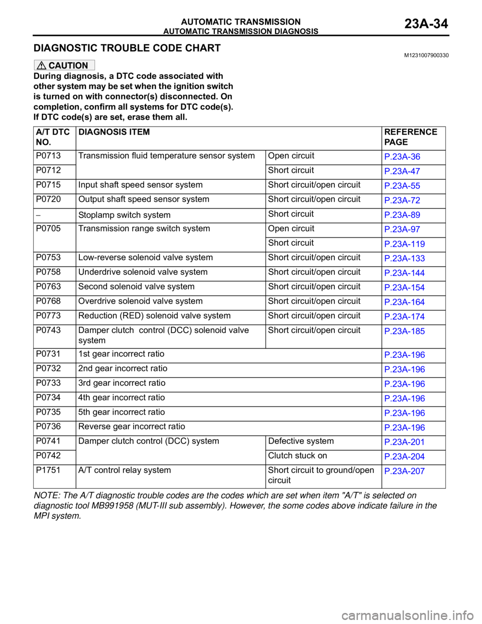
DIAGNOSTIC TROUBLE CODE CHARTM1231007900330
During diagnosis, a DTC code associated with
other system may be set when the ignition switch
is turned on with connector(s) disconnected. On
completion, confirm all systems for DTC code(s).
If DTC code(s) are set, erase them all.
NOTE: The A/T diagnostic trouble codes are the codes which are set when item "A/T" is selected on
diagnostic tool MB991958 (MUT-III sub assembly). However, the some codes above indicate failure in the
MPI system.A/T DTC
NO.DIAGNOSIS ITEM REFERENCE
PA G E
P0713 Transmission fluid temperature sensor system Open circuit
P.23A-36
P0712 Short circuit
P.23A-47
P0715 Input shaft speed sensor system Short circuit/open circuit
P.23A-55
P0720 Output shaft speed sensor system Short circuit/open circuit
P.23A-72
Stoplamp switch systemShort circuit
P.23A-89
P0705 Transmission range switch system Open circuit
P.23A-97
Short circuit
P.23A-119
P0753 Low-reverse solenoid valve system Short circuit/open circuit
P.23A-133
P0758 Underdrive solenoid valve system Short circuit/open circuit
P.23A-144
P0763 Second solenoid valve system Short circuit/open circuit
P.23A-154
P0768 Overdrive solenoid valve system Short circuit/open circuit
P.23A-164
P0773 Reduction (RED) solenoid valve system Short circuit/open circuit
P.23A-174
P0743 Damper clutch control (DCC) solenoid valve
systemShort circuit/open circuit
P.23A-185
P0731 1st gear incorrect ratio
P.23A-196
P0732 2nd gear incorrect ratio
P.23A-196
P0733 3rd gear incorrect ratio
P.23A-196
P0734 4th gear incorrect ratio
P.23A-196
P0735 5th gear incorrect ratio
P.23A-196
P0736 Reverse gear incorrect ratio
P.23A-196
P0741 Damper clutch control (DCC) system Defective system
P.23A-201
P0742 Clutch stuck on
P.23A-204
P1751 A/T control relay system Short circuit to ground/open
circuitP.23A-207
Page 1494 of 1500

AUTOMATIC TRANSMISSION DIAGNOSIS
AUTOMATIC TRANSMISSION23A-35
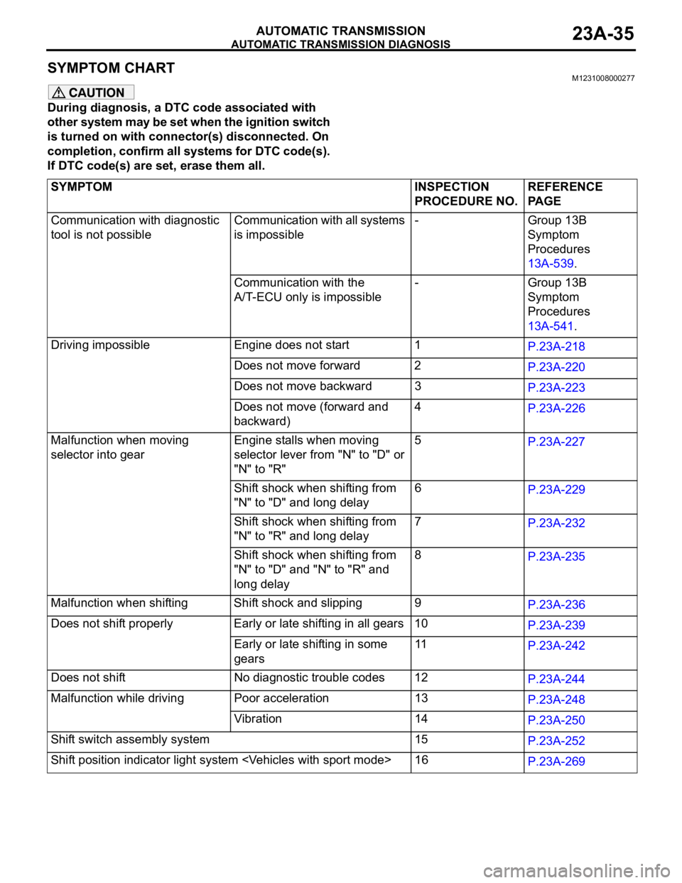
SYMPTOM CHART M1231008000277
During diagnosis, a DTC code associated with
other system may be set when the ignition switch
is turned on with connector(s) disconnected. On
completion, confirm all systems for DTC code(s).
If DTC code(s) are set, erase them all.
SYMPTOM INSPECTION
PROCEDURE NO.REFERENCE
PA G E
Communication with diagnostic
tool is not possibleCommunication with all systems
is impossible- Group 13B
Symptom
Procedures
13A-539.
Communication with the
A/T-ECU only is impossible- Group 13B
Symptom
Procedures
13A-541.
Driving impossible Engine does not start 1
P.23A-218
Does not move forward 2
P.23A-220
Does not move backward 3
P.23A-223
Does not move (forward and
backward)4
P.23A-226
Malfunction when moving
selector into gearEngine stalls when moving
selector lever from "N" to "D" or
"N" to "R"5
P.23A-227
Shift shock when shifting from
"N" to "D" and long delay6
P.23A-229
Shift shock when shifting from
"N" to "R" and long delay 7
P.23A-232
Shift shock when shifting from
"N" to "D" and "N" to "R" and
long delay 8
P.23A-235
Malfunction when shifting Shift shock and slipping 9
P.23A-236
Does not shift properly Early or late shifting in all gears 10
P.23A-239
Early or late shifting in some
gears11
P.23A-242
Does not shift No diagnostic trouble codes 12
P.23A-244
Malfunction while driving Poor acceleration 13
P.23A-248
Vibration 14
P.23A-250
Shift switch assembly system 15
P.23A-252
Shift position indicator light system 16
P.23A-269