Page 1402 of 1500
AUTO-CRUISE CONTROL
ENGINE AND EMISSION CONTROL17-71
ON-VEHICLE SERVICE
AUTO-CRUISE CONTROL SWITCH CHECKM1172001200054
AUTO-CRUISE CONTROL MAIN SWITCH CHECK
1. Turn the ignition switch to the "ON" position.
2. Check that the "CRUISE" indicator lamp within the
combination meter illuminates when the "CRUISE" (MAIN)
switch is switched "ON".
AUTO-CRUISE CONTROL SETTING
1. Switch "ON" the "CRUISE" (MAIN) switch.
2. Drive at the desired speed, above approximately 40 km/h.
3. Push the auto-cruise control switch in the direction of the
arrow.
4. Check to be sure that when the switch is released the speed
is the desired constant speed.
NOTE: If the vehicle speed decreases to approximately 15
km/h below the set speed because of climbing a hill for
example, it is normal for the auto-cruise control to be can-
celled.
Page 1403 of 1500

AUTO-CRUISE CONTROL
ENGINE AND EMISSION CONTROL17-72
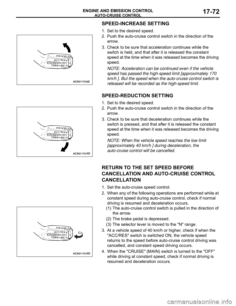
SPEED-INCREASE SETTING
1. Set to the desired speed.
2. Push the auto-cruise control switch in the direction of the
arrow.
3. Check to be sure that acceleration continues while the
switch is held, and that after it is released the constant
speed at the time when it was released becomes the driving
speed.
NOTE: Acceleration can be continued even if the vehicle
speed has passed the high-speed limit [approximately 170
km/h ]. But the speed when the auto-cruise control switch is
released will be recorded as the high-speed limit.
SPEED-REDUCTION SETTING
1. Set to the desired speed.
2. Push the auto-cruise control switch in the direction of the
arrow.
3. Check to be sure that deceleration continues while the
switch is pressed, and that after it is released the constant
speed at the time when it was released becomes the driving
speed.
NOTE: When the vehicle speed reaches the low limit
[approximately 40 km/h ] during deceleration, the
auto-cruise control will be cancelled.
RETURN TO THE SET SPEED BEFORE
CANCELLATION AND AUTO-CRUISE CONTROL
CANCELLATION
1. Set the auto-cruise speed control.
2. When any of the following operations are performed while at
constant speed during auto-cruise control, check if normal
driving is resumed and deceleration occurs.
(1) The auto-cruise control switch is pulled in the direction of
the arrow.
(2) The brake pedal is depressed.
(3) The selector lever is moved to the "N" range.
3. At a vehicle speed of 40 km/h or higher, check if when the
"ACC/RES" switch is switched ON, the vehicle speed
returns to the speed before auto-cruise control driving was
cancelled, and constant speed driving occurs.
4. When the "CRUISE" (MAIN) switch is turned to the "OFF"
while driving at constant speed, check if normal driving is
resumed and deceleration occurs.
Page 1416 of 1500
SPECIFICATIONS
ENGINE AND EMISSION CONTROL17-85
SPECIFICATIONS
FASTENER TIGHTENING SPECIFICATIONSM1173006400324
SERVICE SPECIFICATIONSM1173000300545
ITEM SPECIFICATION
Auto-cruise control system
Lower cover cap bolt 9.0
2.0 Nm (80 17 in-lb)
Steering wheel assembly nut 41
8 Nm (30 6 ft-lb)
Engine control system
Accelerator pedal assembly nut 13
2 Nm ( 111 22 in-lb)
ITEMSSTANDARD VALUE
Engine control system
Curb idle speed r/min 3.8L Engine 680
100
Emission control system
Purge flow cm
3/s (SCFH) [at 80 95C (176 205F) with sudden revving]20 (2.5)
Evaporative emission purge solenoid coil resistance [at 20
C)] 16
Page 1419 of 1500

GENERAL DESCRIPTION
FRONT AXLE26-2
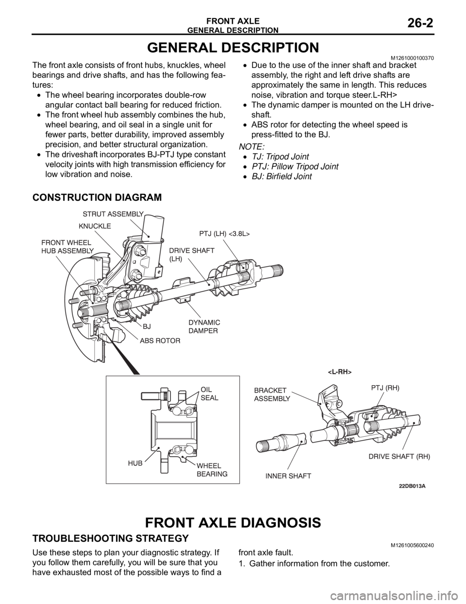
GENERAL DESCRIPTIONM1261000100370
The front axle consists of front hubs, knuckles, wheel
bearings and drive shafts, and has the following fea-
tures:
The wheel bearing incorporates double-row
angular contact ball bearing for reduced friction.
The front wheel hub assembly combines the hub,
wheel bearing, and oil seal in a single unit for
fewer parts, better durability, improved assembly
precision, and better structural organization.
The driveshaft incorporates BJ-PTJ type constant
velocity joints with high transmission efficiency for
low vibration and noise.
Due to the use of the inner shaft and bracket
assembly, the right and left drive shafts are
approximately the same in length. This reduces
noise, vibration and torque steer.L-RH>
The dynamic damper is mounted on the LH drive-
shaft.
ABS rotor for detecting the wheel speed is
press-fitted to the BJ.
NOTE: .
TJ: Tripod Joint
PTJ: Pillow Tripod Joint
BJ: Birfield Joint
CONSTRUCTION DIAGRAM
FRONT AXLE DIAGNOSIS
TROUBLESHOOTING STRATEGYM1261005600240
Use these steps to plan your diagnostic strategy. If
you follow them carefully, you will be sure that you
have exhausted most of the possible ways to find a front axle fault.
1. Gather information from the customer.
Page 1426 of 1500
Page 1430 of 1500

DRIVE SHAFT ASSEMBLY
FRONT AXLE26-13
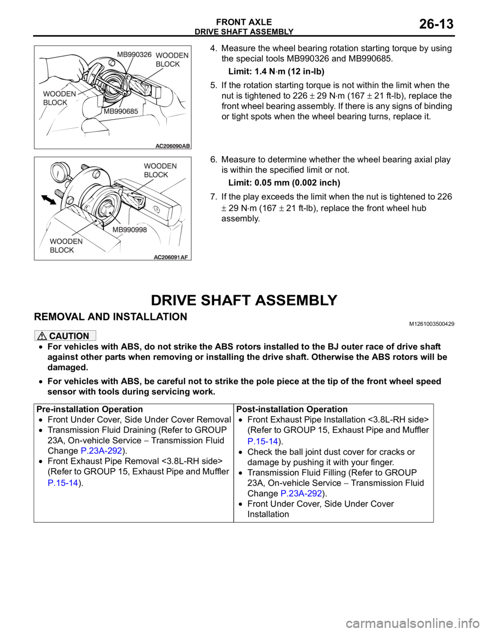
4. Measure the wheel bearing rotation starting torque by using
the special tools MB990326 and MB990685.
Limit: 1.4 N
m (12 in-lb)
5. If the rotation starting torque is not within the limit when the
nut is tightened to 226
29 Nm (167 21 ft-lb), replace the
front wheel bearing assembly. If there is any signs of binding
or tight spots when the wheel bearing turns, replace it.
6. Measure to determine whether the wheel bearing axial play
is within the specified limit or not.
Limit: 0.05 mm (0.002 inch)
7. If the play exceeds the limit when the nut is tightened to 226
29 Nm (167 21 ft-lb), replace the front wheel hub
assembly.
DRIVE SHAFT ASSEMBLY
REMOVAL AND INSTALLATIONM1261003500429
For vehicles with ABS, do not strike the ABS rotors installed to the BJ outer race of drive shaft
against other parts when removing or installing the drive shaft. Otherwise the ABS rotors will be
damaged.
For vehicles with ABS, be careful not to strike the pole piece at the tip of the front wheel speed
sensor with tools during servicing work.
Pre-installation Operation
Front Under Cover, Side Under Cover Removal
Transmission Fluid Draining (Refer to GROUP
23A, On-vehicle Service
Transmission Fluid
Change P.23A-292).
Front Exhaust Pipe Removal <3.8L-RH side>
(Refer to GROUP 15, Exhaust Pipe and Muffler
P.15-14).Post-installation Operation
Front Exhaust Pipe Installation <3.8L-RH side>
(Refer to GROUP 15, Exhaust Pipe and Muffler
P.15-14).
Check the ball joint dust cover for cracks or
damage by pushing it with your finger.
Transmission Fluid Filling (Refer to GROUP
23A, On-vehicle Service
Transmission Fluid
Change P.23A-292).
Front Under Cover, Side Under Cover
Installation
Page 1431 of 1500
Page 1449 of 1500

GENERAL DESCRIPTION
REAR AXLE27-2
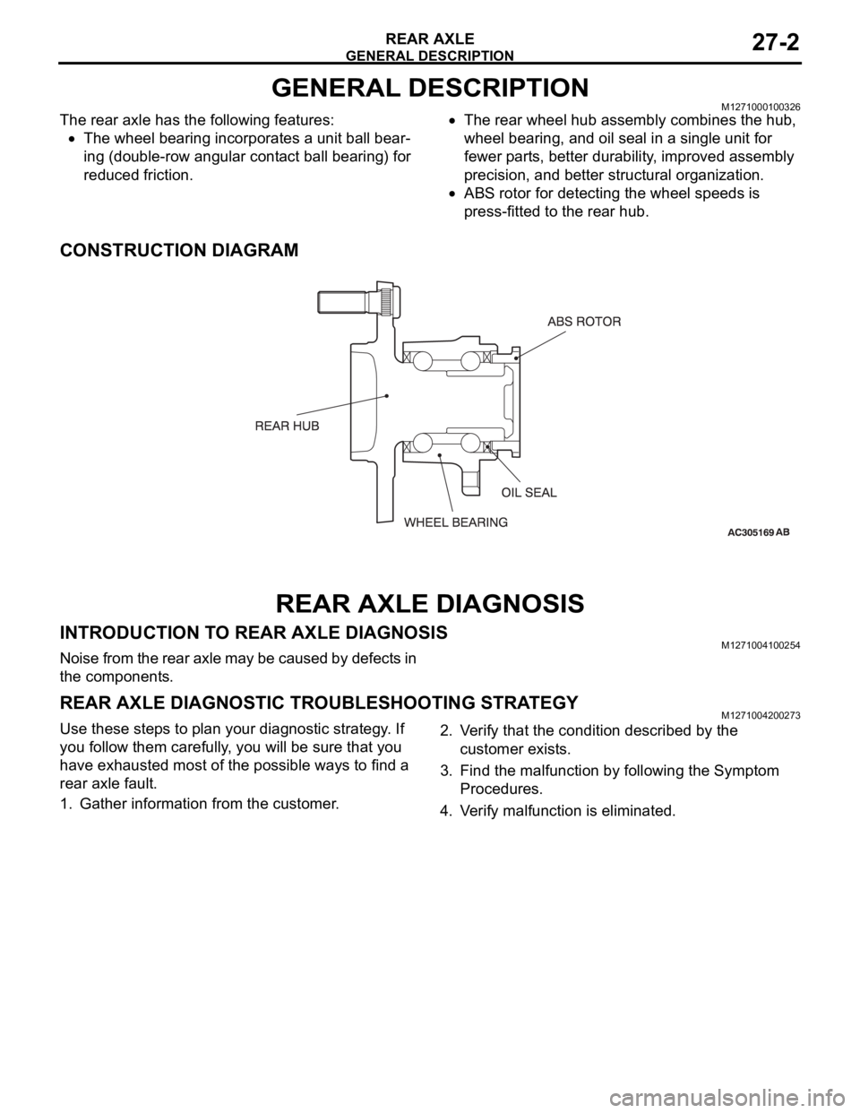
GENERAL DESCRIPTIONM1271000100326
The rear axle has the following features:
The wheel bearing incorporates a unit ball bear-
ing (double-row angular contact ball bearing) for
reduced friction.
The rear wheel hub assembly combines the hub,
wheel bearing, and oil seal in a single unit for
fewer parts, better durability, improved assembly
precision, and better structural organization.
ABS rotor for detecting the wheel speeds is
press-fitted to the rear hub.
CONSTRUCTION DIAGRAM
REAR AXLE DIAGNOSIS
INTRODUCTION TO REAR AXLE DIAGNOSISM1271004100254
Noise from the rear axle may be caused by defects in
the components.
REAR AXLE DIAGNOSTIC TROUBLESHOOTING STRATEGYM1271004200273
Use these steps to plan your diagnostic strategy. If
you follow them carefully, you will be sure that you
have exhausted most of the possible ways to find a
rear axle fault.
1. Gather information from the customer.2. Verify that the condition described by the
customer exists.
3. Find the malfunction by following the Symptom
Procedures.
4. Verify malfunction is eliminated.