2005 MITSUBISHI 380 key
[x] Cancel search: keyPage 1138 of 1500

KEYLESS ENTRY SYSTEM
BODY42-71
KEYLESS ENTRY SYSTEM INSPECTIONBGBHCDAE
Check the following items. If defective, refer to GROUP 54B,
SWS Diagnosis P.54B-10).
1. Operate the transmitter to check that the doors can be
locked and unlocked.
NOTE: The adjustment function allows you to change the
unlock operation setting as follows. Prior to that check, con-
firm which setting is activated.
.
a. When the unlock button is pressed once, the driver's
door will be unlocked. Then when the button is pressed
once again, all the doors will be opened (initial setting).
b. When the unlock button is pressed only once, all the
doors will be opened.
2. Press the trunk lid button of transmitter twice (press once,
and then press again within 5 seconds) and confirm that the
trunk lid opens.
3. Operate the transmitter to check that the answerback
function works in response to doors locking/unlocking.
NOTE: The adjustment function allows you to change the
hazard answerback setting as follows. Prior to that check,
confirm which setting is activated.
.
a. Turn-signal lights: Flash once when doors are locked,
and twice when unlocked (initial setting)
b. Turn-signal lights: Flash once when doors are locked,
but does not flash when unlocked.
c. Turn-signal lights: Do not flash when doors are locked,
but flash twice when unlocked.
d. Turn-signal lights: Do not flash when doors are locked
and unlocked.
NOTE: The adjustment function allows you to change the
horn answerback setting as follows. Prior to that check, con-
firm which setting is activated.
.
a. Horn: Sounds once when the lock button is pressed.
b. Horn: Sounds once when the lock button is pressed (ini-
tial setting).
c. Horn: Does not sound.
KEYLESS ENTRY SYSTEM TIMER LOCK
FUNCTION INSPECTION
BGBEBDIA
If the doors are not locked within 30 seconds after the unlock
button is pressed, refer to GROUP 54B, SWS Diagnosis
P.54B-10.
NOTE: If either of the doors is opened or the key is inserted in
the ignition switch within that 30-second period, the timer lock
function will be cancelled.
Page 1139 of 1500

KEYLESS ENTRY SYSTEM
BODY42-72
NOTE: The adjustment function allows you to change the timer
lock period from 30 seconds (initial setting) to 60, 120 or 180
seconds. Prior to this inspection, confirm which setting is acti-
vated.
ENABLING/DISABLING THE ANSWERBACK
FUNCTION
BGBDGCGD
When the doors are locked or unlocked by using the transmit-
ter, the dome light will flash/illuminate, the turn-signal lights will
flash (hazard answerback), or the horn will sound (horn
answerback) to inform the driver.
The hazard answerback and horn answerback functions can be
enabled or disabled according to the following procedure:
ENABLING/DISABLING THE HAZARD
ANSWERBACK FUNCTION
.
How to adjust hazard answerback when the trans-
mitter is used to lock doors
1. Remove the ignition key.
2. Push the ”unlock” button and then push the ”lock“ button
within 4 seconds to 10 seconds.
3. Release the ”lock” button within 10 seconds after Step 2 and
then release the “unlock” button. The ETACS-ECU tone
alarm will sound, indicating that the hazard answerback
function can be enabled or disabled when the doors are
locked.
Enable the hazard answerback function when the
doors are locked: The ETACS-ECU tone alarm will
sound once.
Disable the hazard answerback function when the
doors are locked: The ETACS-ECU tone alarm will
sound twice.
.
How to adjust hazard answerback when the
transmitter is used to unlock doors
1. Remove the ignition key.
2. Push the ”unlock” button and then push the ”lock“ button
within 4 seconds to 10 seconds.
3. Release the ”lock” button within 10 seconds after Step 2 and
then release the “unlock” button. The ETACS-ECU tone
alarm will sound, indicating that the hazard answerback
function can be enabled or disabled when the door are
unlocked.
Enable the hazard answerback function when the
doors are unlocked: The ETACS-ECU tone alarm
will sound once.
Disable the hazard answerback function when the
doors are unlocked: The ETACS-ECU tone alarm
will sound twice.
Page 1140 of 1500

KEYLESS ENTRY SYSTEM
BODY42-73
ENABLING/DISABLING THE HORN
ANSWERBACK FUNCTION
.
1. Remove the ignition key.
2. Push the ”unlock” button and then push the ”lock“ button
within 4 seconds to 10 seconds.
3. Release the ”lock” button within 10 seconds after Step 2 and
then release the “unlock” button. The ETACS-ECU tone
alarm will sound, indicating that the horn answerback
function can be enabled or disabled.
Enable the horn answerback function*: The
ETACS-ECU tone alarm will sound once.
Disable the horn answerback function: The
ETACS-ECU tone alarm will sound twice.
Enable the horn answerback function**: The
ETACS-ECU tone alarm will sound three times.
NOTE: .
*: The horn will sound if "LOCK" button is pressed with the
doors locked.
**: The horn will sound if the doors are locked with the key-
less entry system.
HOW TO REGISTER SECRET CODEBGBHCCCB
Required Special Tools:
: MUT-III Sub Assembly
MB991824: Vehicle Communication Interface (V.C.I.)
MB991910: MUT-III Main harness A
Each individual secret code is registered inside the transmitter,
and so it is necessary to resister these codes with the
EEPROM inside the receiver in the following cases.
When the transmitter or ETACS-ECU is replaced
If more transmitters are to be used
If it appears that a problem is occurring because of faulty
registration of a code.
A maximum of four different codes can be stored in the
EEPROM memory (four different transmitters can be used).
When the code for the first transmitter is registered, the previ-
ously registered codes for all transmitters are cleared. There-
fore, if you are using four transmitters or are adding more
transmitters, the codes for all transmitters must be registered at
the same time.
WHEN SPECIAL TOOL MB991824 (V.C.I.) IS USED
.
1. Check that the doors lock normally when the key is used.
2. Insert the ignition key.
Page 1141 of 1500
KEYLESS ENTRY SYSTEM
BODY42-74
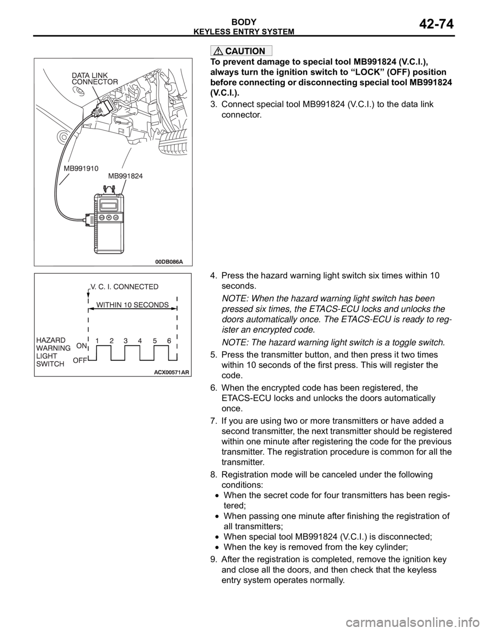
To prevent damage to special tool MB991824 (V.C.I.),
always turn the ignition switch to “LOCK” (OFF) position
before connecting or disconnecting special tool MB991824
(V.C.I.).
3. Connect special tool MB991824 (V.C.I.) to the data link
connector.
4. Press the hazard warning light switch six times within 10
seconds.
NOTE: When the hazard warning light switch has been
pressed six times, the ETACS-ECU locks and unlocks the
doors automatically once. The ETACS-ECU is ready to reg-
ister an encrypted code.
NOTE: The hazard warning light switch is a toggle switch.
5. Press the transmitter button, and then press it two times
within 10 seconds of the first press. This will register the
code.
6. When the encrypted code has been registered, the
ETACS-ECU locks and unlocks the doors automatically
once.
7. If you are using two or more transmitters or have added a
second transmitter, the next transmitter should be registered
within one minute after registering the code for the previous
transmitter. The registration procedure is common for all the
transmitter.
8. Registration mode will be canceled under the following
conditions:
When the secret code for four transmitters has been regis-
tered;
When passing one minute after finishing the registration of
all transmitters;
When special tool MB991824 (V.C.I.) is disconnected;
When the key is removed from the key cylinder;
9. After the registration is completed, remove the ignition key
and close all the doors, and then check that the keyless
entry system operates normally.
Page 1246 of 1500
PRECAUTIONS BEFORE SERVICE
GENERAL00-25
APPLICATION OF ANTI-CORROSION AGENTS
AND UNDERCOATS
M1001011000043
Do not to apply oil or grease to the heated oxygen sensor. If
applied, the sensor may malfunction. Protect the heated oxy-
gen sensor with a cover before applying anti-corrosion agent,
etc.
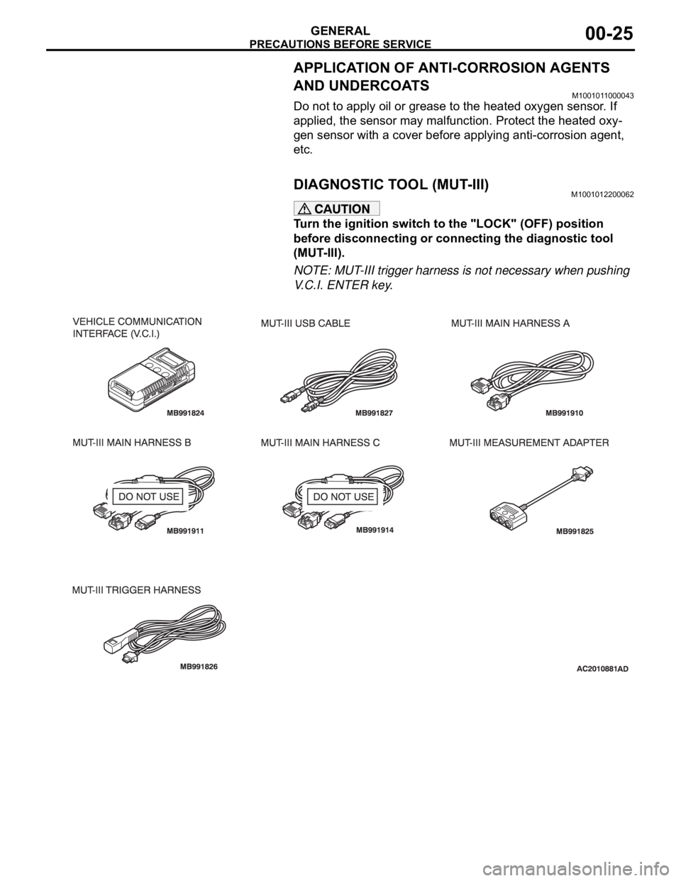
DIAGNOSTIC TOOL (MUT-III)M1001012200062
Turn the ignition switch to the "LOCK" (OFF) position
before disconnecting or connecting the diagnostic tool
(MUT-III).
NOTE: MUT-III trigger harness is not necessary when pushing
V.C.I. ENTER key.
Page 1247 of 1500
TOWING AND HOISTING
GENERAL00-26
TOWING AND HOISTINGM1001000800380
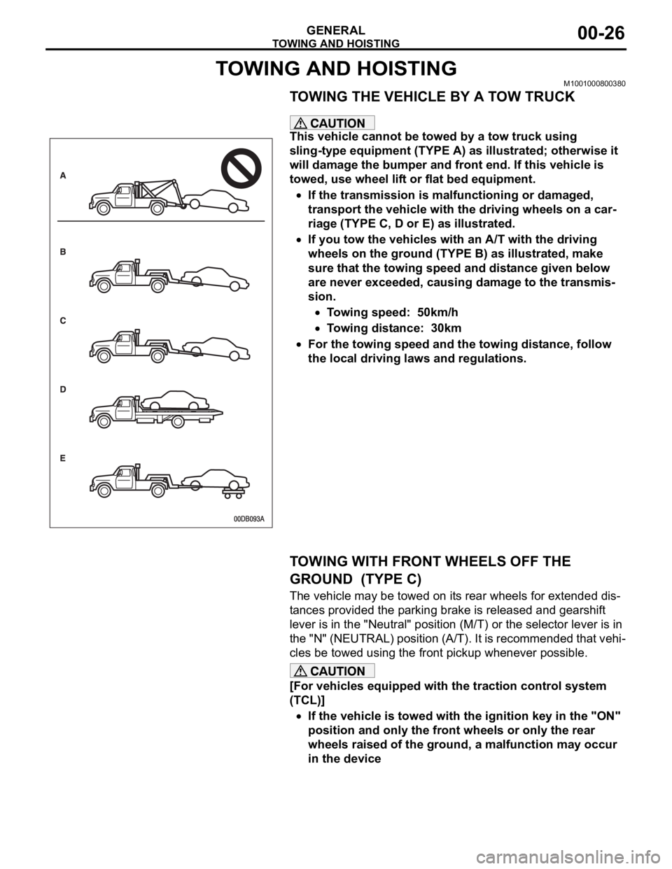
TOWING THE VEHICLE BY A TOW TRUCK
.
This vehicle cannot be towed by a tow truck using
sling-type equipment (TYPE A) as illustrated; otherwise it
will damage the bumper and front end. If this vehicle is
towed, use wheel lift or flat bed equipment.
If the transmission is malfunctioning or damaged,
transport the vehicle with the driving wheels on a car-
riage (TYPE C, D or E) as illustrated.
If you tow the vehicles with an A/T with the driving
wheels on the ground (TYPE B) as illustrated, make
sure that the towing speed and distance given below
are never exceeded, causing damage to the transmis-
sion.
Towing speed: 50km/h
Towing distance: 30km
For the towing speed and the towing distance, follow
the local driving laws and regulations.
.
TOWING WITH FRONT WHEELS OFF THE
GROUND (TYPE C)
The vehicle may be towed on its rear wheels for extended dis-
tances provided the parking brake is released and gearshift
lever is in the "Neutral" position (M/T) or the selector lever is in
the "N" (NEUTRAL) position (A/T). It is recommended that vehi-
cles be towed using the front pickup whenever possible.
[For vehicles equipped with the traction control system
(TCL)]
If the vehicle is towed with the ignition key in the "ON"
position and only the front wheels or only the rear
wheels raised of the ground, a malfunction may occur
in the device
.
Page 1248 of 1500
TOWING AND HOISTING
GENERAL00-27
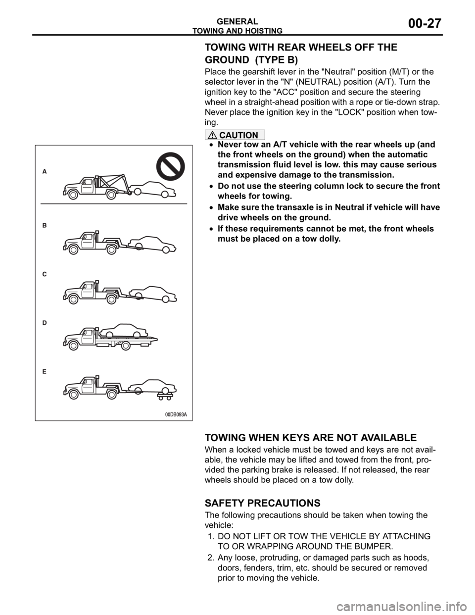
TOWING WITH REAR WHEELS OFF THE
GROUND (TYPE B)
Place the gearshift lever in the "Neutral" position (M/T) or the
selector lever in the "N" (NEUTRAL) position (A/T). Turn the
ignition key to the "ACC" position and secure the steering
wheel in a straight-ahead position with a rope or tie-down strap.
Never place the ignition key in the "LOCK" position when tow-
ing.
Never tow an A/T vehicle with the rear wheels up (and
the front wheels on the ground) when the automatic
transmission fluid level is low. this may cause serious
and expensive damage to the transmission.
Do not use the steering column lock to secure the front
wheels for towing.
Make sure the transaxle is in Neutral if vehicle will have
drive wheels on the ground.
If these requirements cannot be met, the front wheels
must be placed on a tow dolly.
.
TOWING WHEN KEYS ARE NOT AVAILABLE
When a locked vehicle must be towed and keys are not avail-
able, the vehicle may be lifted and towed from the front, pro-
vided the parking brake is released. If not released, the rear
wheels should be placed on a tow dolly.
.
SAFETY PRECAUTIONS
The following precautions should be taken when towing the
vehicle:
1. DO NOT LIFT OR TOW THE VEHICLE BY ATTACHING
TO OR WRAPPING AROUND THE BUMPER.
2. Any loose, protruding, or damaged parts such as hoods,
doors, fenders, trim, etc. should be secured or removed
prior to moving the vehicle.
Page 1272 of 1500
MAINTENANCE SERVICE
GENERAL00-51
18. SUSPENSION SYSTEM (INSPECT FOR
LOOSENESS AND DAMAGE)
M1001009600048
Visually inspect the front/rear suspension components for dete-
rioration and damage. Re-tighten the front/rear suspension
components retaining bolts to specified torque.
19. SRS AIR BAG (INSPECT FOR SRS SYSTEM)M1001003700326
The entire SRS including air bag and pre-tensioner seat belt
must be inspected by an authorized MITSUBISHI MOTORS
dealer 10 years.
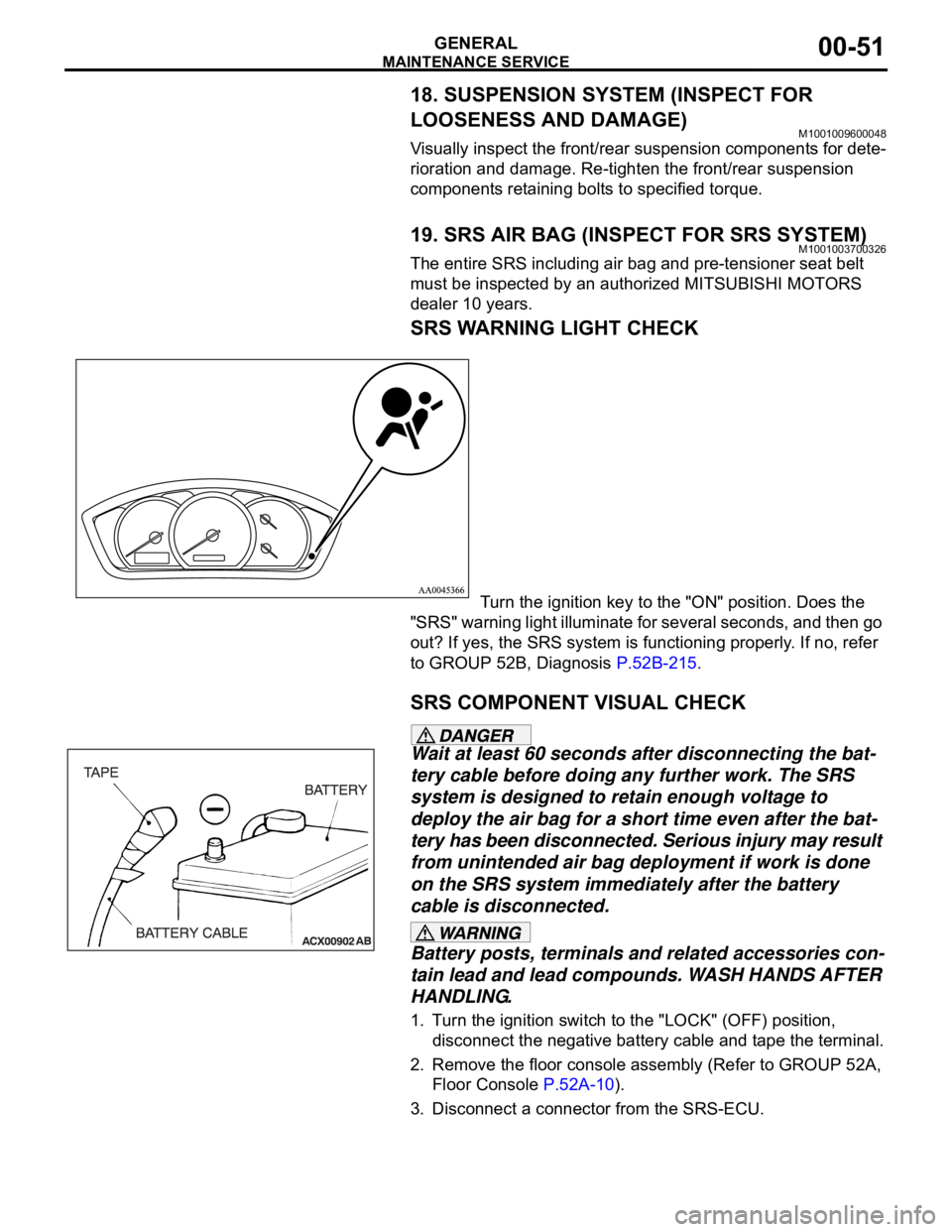
SRS WARNING LIGHT CHECK
Turn the ignition key to the "ON" position. Does the
"SRS" warning light illuminate for several seconds, and then go
out? If yes, the SRS system is functioning properly. If no, refer
to GROUP 52B, Diagnosis P.52B-215.
SRS COMPONENT VISUAL CHECK
Wait at least 60 seconds after disconnecting the bat-
tery cable before doing any further work. The SRS
system is designed to retain enough voltage to
deploy the air bag for a short time even after the bat-
tery has been disconnected. Serious injury may result
from unintended air bag deployment if work is done
on the SRS system immediately after the battery
cable is disconnected.
Battery posts, terminals and related accessories con-
tain lead and lead compounds. WASH HANDS AFTER
HANDLING.
1. Turn the ignition switch to the "LOCK" (OFF) position,
disconnect the negative battery cable and tape the terminal.
2. Remove the floor console assembly (Refer to GROUP 52A,
Floor Console P.52A-10).
3. Disconnect a connector from the SRS-ECU.