Page 686 of 1500
FORGOTTEN KEY PREVENTION FUNCTION
CIRCUIT DIAGRAMS90-109
FORGOTTEN KEY PREVENTION FUNCTIONM1901016100361
Page 687 of 1500
FORGOTTEN KEY PREVENTION FUNCTION
CIRCUIT DIAGRAMS90-110
Page 689 of 1500
IGNITION KEY REMINDER TONE ALARM
CIRCUIT DIAGRAMS90-112
IGNITION KEY REMINDER TONE ALARMM1901011300735
Page 841 of 1500
SPECIAL TOOLS
HEATER, AIR CONDITIONING AND VENTILATION55-140
A: MB991824
B: MB991827
C: MB991910
D: MB991911
E: MB991914
F: MB991825
G: MB991826
MUT-III Sub
Assembly
A: Vehicle
communicatio
n interface
(V.C.I.)
B: MUT-III USB
cable
C: MUT-III main
harness A
(Vehicles with
CAN
communicatio
n system)
D: MUT-III main
harness B
(Vehicles
without CAN
communicatio
n system)
E: MUT-III main
harness C (for
Daimler
Chrysler
models only)
F: MUT-III
measurement
adapter
G: MUT-III
Trigger
HarnessMB991824-KIT
NOTE: . G:
MB991826 MUT-III
Trigger Harness is not
necessary when
pushing V.C.I.
ENTER key.Checking diagnostic trouble codes
For vehicles with CAN
communication, use MUT-III
main harness A to send
simulated vehicle speed. If you
connect MUT-III main harness B
instead, the CAN
communication does not
function correctly. TOOL TOOL NUMBER
AND NAMESUPERSESSION APPLICATION
Page 983 of 1500
CHARGING SYSTEM
ENGINE ELECTRICAL16-6
SPECIAL TOOLM1161000600486
TOOL TOOL NUMBER AND
NAMESUPERSESSION APPLICATION
Diagnostic tool (MUT-III)
A: MB991824
Ve h i c l e
communication
interface (V.C.I.)
B: MB991827
MUT-III USB cable
C: MB991910
MUT-III main harness
A (Vehicles with CAN
communication
system)
D: MB991911
MUT-III main harness
B (Vehicles without
CAN communication
system)
E: MB991914
MUT-III main harness
C (for Daimler Chrysler
models only)
F: MB991825
MUT-III measurement
adapter
G: MB991826
MUT-III trigger
harnessMB991824-KIT
NOTE: G: MB991826
MUT-III Trigger Harness
is not necessary when
pushing V.C.I. ENTER
key.Checking of engine
speed
For vehicles with CAN
communication, use
MUT-III main harness A
to send simulated
vehicle speed. If you
connect MUT-III main
harness B instead, the
CAN communication
does not function
correctly.
MB998467
Alternator harness
connectorMIT530
Micrd 530 charging
system tester.Checking of alternator
("S" terminal voltage)
Page 1026 of 1500

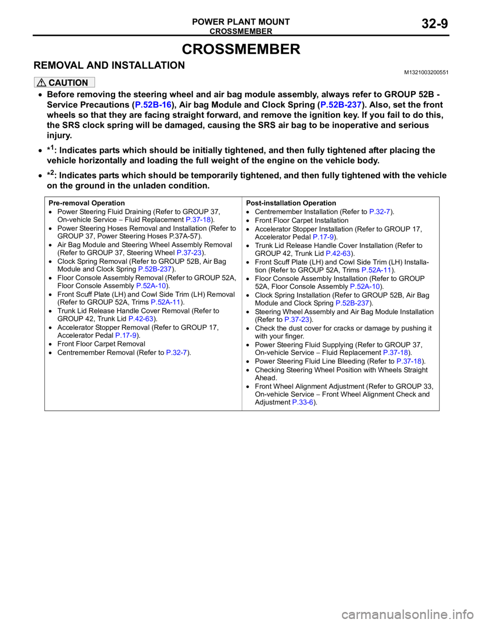
CROSSMEMBER
POWER PLANT MOUNT32-9
CROSSMEMBER
REMOVAL AND INSTALLATIONM1321003200551
Before removing the steering wheel and air bag module assembly, always refer to GROUP 52B -
Service Precautions (P.52B-16), Air bag Module and Clock Spring (P.52B-237). Also, set the front
wheels so that they are facing straight forward, and remove the ignition key. If you fail to do this,
the SRS clock spring will be damaged, causing the SRS air bag to be inoperative and serious
injury.
*1: Indicates parts which should be initially tightened, and then fully tightened after placing the
vehicle horizontally and loading the full weight of the engine on the vehicle body.
*2: Indicates parts which should be temporarily tightened, and then fully tightened with the vehicle
on the ground in the unladen condition.
Pre-removal Operation
Power Steering Fluid Draining (Refer to GROUP 37,
On-vehicle Service Fluid Replacement P.37-18).
Power Steering Hoses Removal and Installation (Refer to
GROUP 37, Power Steering Hoses P.37A-57).
Air Bag Module and Steering Wheel Assembly Removal
(Refer to GROUP 37, Steering Wheel P.37-23).
Clock Spring Removal (Refer to GROUP 52B, Air Bag
Module and Clock Spring P.52B-237).
Floor Console Assembly Removal (Refer to GROUP 52A,
Floor Console Assembly P.52A-10).
Front Scuff Plate (LH) and Cowl Side Trim (LH) Removal
(Refer to GROUP 52A, Trims P.52A-11).
Trunk Lid Release Handle Cover Removal (Refer to
GROUP 42, Trunk Lid P.42-63).
Accelerator Stopper Removal (Refer to GROUP 17,
Accelerator Pedal P.17-9).
Front Floor Carpet Removal
Centremember Removal (Refer to P.32-7).Post-installation Operation
Centremember Installation (Refer to P.32-7).
Front Floor Carpet Installation
Accelerator Stopper Installation (Refer to GROUP 17,
Accelerator Pedal P.17-9).
Trunk Lid Release Handle Cover Installation (Refer to
GROUP 42, Trunk Lid P.42-63).
Front Scuff Plate (LH) and Cowl Side Trim (LH) Installa-
tion (Refer to GROUP 52A, Trims P.52A-11).
Floor Console Assembly Installation (Refer to GROUP
52A, Floor Console Assembly P.52A-10).
Clock Spring Installation (Refer to GROUP 52B, Air Bag
Module and Clock Spring P.52B-237).
Steering Wheel Assembly and Air Bag Module Installation
(Refer to P.37-23).
Check the dust cover for cracks or damage by pushing it
with your finger.
Power Steering Fluid Supplying (Refer to GROUP 37,
On-vehicle Service Fluid Replacement P.37-18).
Power Steering Fluid Line Bleeding (Refer to P.37-18).
Checking Steering Wheel Position with Wheels Straight
Ahead.
Front Wheel Alignment Adjustment (Refer to GROUP 33,
On-vehicle Service
Front Wheel Alignment Check and
Adjustment P.33-6).
Page 1069 of 1500

BODY42-2
DOOR . . . . . . . . . . . . . . . . . . . . . . . . .42-23
GENERAL DESCRIPTION . . . . . .
42-23
CENTRAL DOOR LOCKING SYSTEM
DIAGNOSIS . . . . . . . . . . . . . . . . . . . . . . 42-23
POWER WINDOW DIAGNOSIS . . . . . . 42-23
DOOR DIAGNOSIS . . . . . . . . . . . . . . . . 42-23
INTRODUCTION TO GLASS AND DOOR
DIAGNOSIS . . . . . . . . . . . . . . . . . . . . . . 42-23
GLASS AND DOOR DIAGNOSTIC
TROUBLESHOOTING STRATEGY . . . 42-23
SYMPTOM CHART . . . . . . . . . . . . . . . . 42-24
SYMPTOM PROCEDURES . . . . . . . . . 42-24
HOW TO LOCATE WIND NOISE . . . . . 42-27
SPECIAL TOOLS. . . . . . . . . . . . . .42-28
ON-VEHICLE SERVICE. . . . . . . . .42-30
DOOR FIT ADJUSTMENT. . . . . . . . . . . 42-30
DOOR WINDOW GLASS ADJUSTMENT42-31
GLASS SLIDING MECHANISM CHECK
AND ADJUSTMENT . . . . . . . . . . . . . . . 42-32
POWER WINDOW TIMER FUNCTION
CHECK . . . . . . . . . . . . . . . . . . . . . . . . . 42-32
POWER WINDOW OPERATING
CURRENT CHECK . . . . . . . . . . . . . . . . 42-33
POWER WINDOW RELAY CHECK . . . 42-33
CIRCUIT BREAKER (INCORPORATED IN
THE POWER WINDOW MOTOR)
INSPECTION . . . . . . . . . . . . . . . . . . . . . 42-34
POWER WINDOW CHECK . . . . . . . . . . 42-34
CENTRAL DOOR LOCKING SYSTEM
INSPECTION . . . . . . . . . . . . . . . . . . . . . 42-34
DOOR OUTSIDE HANDLE PLAY CHECK42-35
DOOR INSIDE HANDLE PLAY CHECK 42-35
DOOR ASSEMBLY . . . . . . . . . . . .42-37
REMOVAL AND INSTALLATION . . . . . 42-37
INSPECTION . . . . . . . . . . . . . . . . . . . . . 42-38
DOOR GLASS AND REGULATOR42-39
REMOVAL AND INSTALLATION . . . . . 42-39
INSPECTION . . . . . . . . . . . . . . . . . . . . . 42-43
DOOR HANDLE AND LATCH . . . .42-46
REMOVAL AND INSTALLATION . . . . . 42-46
INSPECTION . . . . . . . . . . . . . . . . . . . . . 42-49
WINDOW GLASS RUNCHANNEL
AND DOOR OPENING
WEATHERSTRIP . . . . . . . . . . . . . .
42-52
REMOVAL AND INSTALLATION . . . . . . 42-52
TRUNK LID. . . . . . . . . . . . . . . . 42-60
TRUNK LID DIAGNOSIS . . . . . . . .
42-60
INTRODUCTION TO TRUNK LID
DIAGNOSIS . . . . . . . . . . . . . . . . . . . . . . 42-60
TRUNK LID DIAGNOSTIC
TROUBLESHOOTING STRATEGY . . . . 42-60
SYMPTOM CHART . . . . . . . . . . . . . . . . 42-60
SYMPTOM PROCEDURES . . . . . . . . . . 42-60
ON-VEHICLE SERVICE . . . . . . . . .42-61
ADJUSTMENT OF CLEARANCE
AROUND TRUNK LID . . . . . . . . . . . . . . 42-61
TRUNK LID LATCH ADJUSTMENT. . . . 42-61
TRUNK LID HEIGHT ADJUSTMENT . . . 42-62
TRUNK LID . . . . . . . . . . . . . . . . . . .42-63
REMOVAL AND INSTALLATION . . . . . . 42-63
INSPECTION . . . . . . . . . . . . . . . . . . . . . 42-65
KEYLESS ENTRY SYSTEM 42-67
GENERAL DESCRIPTION . . . . . . .
42-67
KEYLESS ENTRY SYSTEM
DIAGNOSIS . . . . . . . . . . . . . . . . . .
42-68
SPECIAL TOOL . . . . . . . . . . . . . . .42-68
ON-VEHICLE SERVICE . . . . . . . . .42-69
TRANSMITTER BATTERY CHECK . . . . 42-69
HOW TO REPLACE THE TRANSMITTER
BATTERY . . . . . . . . . . . . . . . . . . . . . . . . 42-70
KEYLESS ENTRY SYSTEM INSPECTION42-71
KEYLESS ENTRY SYSTEM TIMER LOCK
FUNCTION INSPECTION . . . . . . . . . . . 42-71
ENABLING/DISABLING THE
ANSWERBACK FUNCTION . . . . . . . . . 42-72
HOW TO REGISTER SECRET CODE . 42-73
Continued on next page
Page 1090 of 1500

DOOR
BODY42-23
DOOR
GENERAL DESCRIPTIONM1423000100246
OPERATION
.
CENTRAL DOOR LOCKING SYSTEM
The central door locking system operates the door
lock actuator to lock or unlock the doors and the fuel
lid door using the door lock switch built into the front
power window (main or sub) switch or key cylinder
built into the driver's side door outside handle. The
system has the following operations and features:
All doors and fuel lid door can be locked using the
door lock switch built into the front power window
(main or sub ) switch.
Insert the key into the driver's key cylinder and
turn once to the unlock side to unlock the driver's
door and fuel lid door. Turn the key once again to
the unlock side to unlock all doors and fuel lid
door.
The key reminder function automatically unlocks
all doors when door lock operation is performed
and the front doors are opened while the key is
inserted into the ignition switch.
.
POWER WINDOWS
When the power window (main or sub) switch is
operated, the door windows will open or close. This
system has the following operations and features:
A power window lock switch on the power win-
dow main switch prevents the door window glass
from opening/closing with the front passenger's
and rear power window sub switch.
The power window of the door window glass can
be opened/closed for 30 seconds with the timer
function after the ignition switch is turned OFF.
(The timer expires if the front door is
opened when the timer is in operation).
The power window main switch contains a
one-touch down switch that will automatically
open the driver's side door window only.
CENTRAL DOOR LOCKING SYSTEM DIAGNOSISM1427000700217
The central door locking system is controlled by the
simplified wiring system (SWS). Refer to GROUP
54B, SWS Diagnosis P.54B-57.
POWER WINDOW DIAGNOSISM1429000700224
The power window is controlled by the simplified wir-
ing system (SWS). Refer to GROUP 54B, SWS
Diagnosis P.54B-57.
DOOR DIAGNOSIS
INTRODUCTION TO GLASS AND DOOR DIAGNOSISM1423007300241
Glass and door faults include water leaks and
improper opening and closing. Causes for these
faults can include faults in the glass, weatherstrip,
drain hole, waterproof film or door installation.
GLASS AND DOOR DIAGNOSTIC TROUBLESHOOTING STRATEGYM1423006700246
Use these steps to plan your diagnostic strategy. If
you follow them carefully, you will be sure that you
have exhausted most of the possible ways to find a
glass and door fault.
1. Gather information from the customer.2. Verify that the condition described by the
customer exists.
3. Find the malfunction by following the Symptom
Chart.
4. Verify malfunction is eliminated.