2005 MITSUBISHI 380 check engine
[x] Cancel search: check enginePage 1005 of 1500
STARTING SYSTEM
ENGINE ELECTRICAL16-28
INSPECTIONM1162001300102.
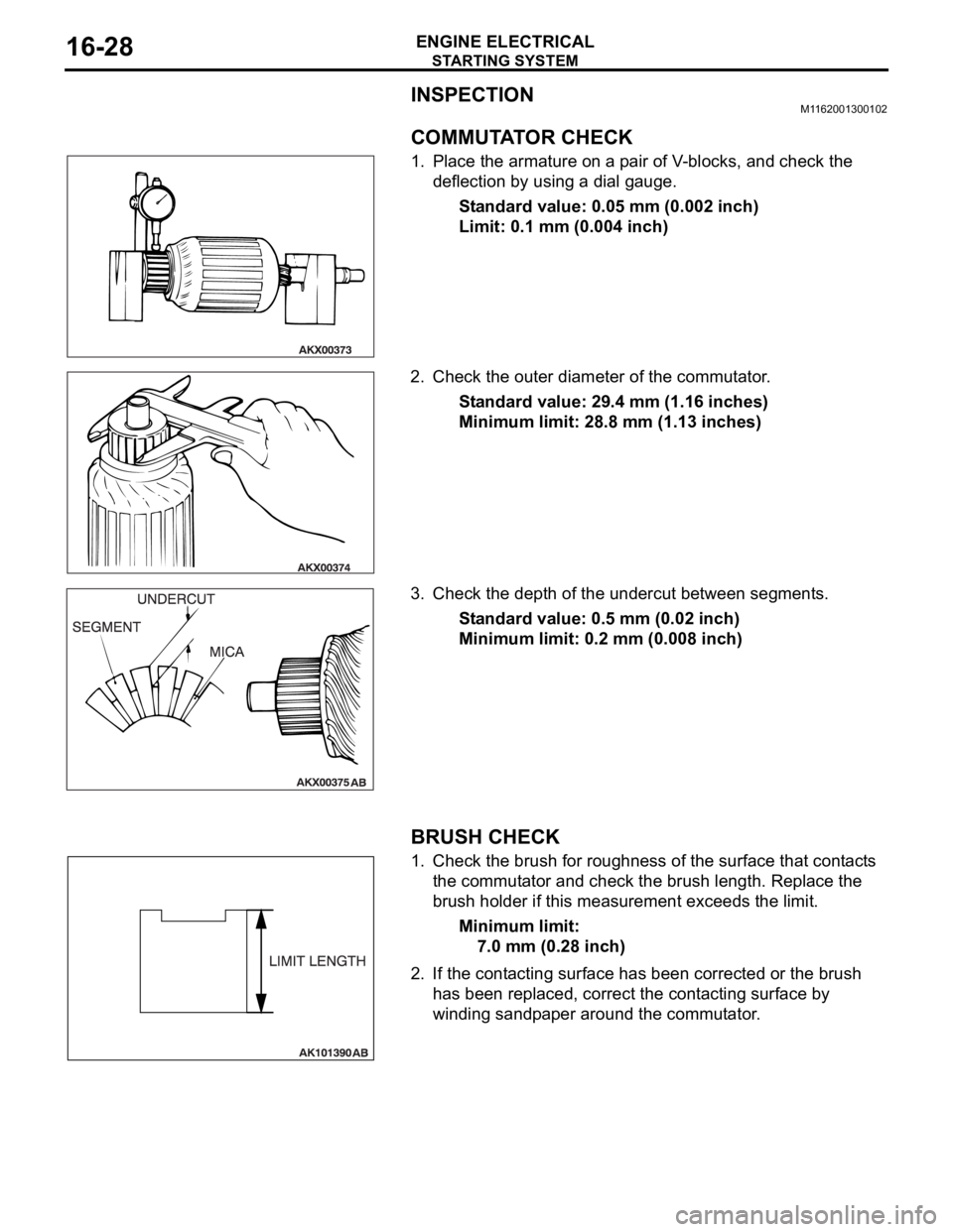
COMMUTATOR CHECK
1. Place the armature on a pair of V-blocks, and check the
deflection by using a dial gauge.
Standard value: 0.05 mm (0.002 inch)
Limit: 0.1 mm (0.004 inch)
2. Check the outer diameter of the commutator.
Standard value: 29.4 mm (1.16 inches)
Minimum limit: 28.8 mm (1.13 inches)
3. Check the depth of the undercut between segments.
Standard value: 0.5 mm (0.02 inch)
Minimum limit: 0.2 mm (0.008 inch)
.
BRUSH CHECK
1. Check the brush for roughness of the surface that contacts
the commutator and check the brush length. Replace the
brush holder if this measurement exceeds the limit.
Minimum limit:
7.0 mm (0.28 inch)
2. If the contacting surface has been corrected or the brush
has been replaced, correct the contacting surface by
winding sandpaper around the commutator.
.
Page 1006 of 1500
STARTING SYSTEM
ENGINE ELECTRICAL16-29
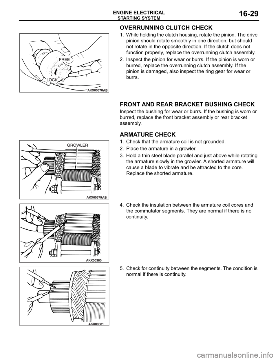
OVERRUNNING CLUTCH CHECK
1. While holding the clutch housing, rotate the pinion. The drive
pinion should rotate smoothly in one direction, but should
not rotate in the opposite direction. If the clutch does not
function properly, replace the overrunning clutch assembly.
2. Inspect the pinion for wear or burrs. If the pinion is worn or
burred, replace the overrunning clutch assembly. If the
pinion is damaged, also inspect the ring gear for wear or
burrs.
.
FRONT AND REAR BRACKET BUSHING CHECK
Inspect the bushing for wear or burrs. If the bushing is worn or
burred, replace the front bracket assembly or rear bracket
assembly.
.
ARMATURE CHECK
1. Check that the armature coil is not grounded.
2. Place the armature in a growler.
3. Hold a thin steel blade parallel and just above while rotating
the armature slowly in the growler. A shorted armature will
cause a blade to vibrate and be attracted to the core.
Replace the shorted armature.
4. Check the insulation between the armature coil cores and
the commutator segments. They are normal if there is no
continuity.
5. Check for continuity between the segments. The condition is
normal if there is continuity.
Page 1008 of 1500

IGNITION SYSTEM
ENGINE ELECTRICAL16-31
ON-VEHICLE SERVICE
KNOCK CONTROL SYSTEM CHECKM1163001800081
Check the knock sensor circuit if diagnostic trouble code, No.
P0325 is shown.
Refer to GROUP 13B, Multiport Fuel Injection (MPI)
Multiport
Fuel Injection (MPI) Diagnosis
Diagnostic Trouble Code Pro-
cedures
DTC P0325 : Knock Sensor Circuit 13A-346.
IGNITION COIL CHECK M1163001200380
Check by the following procedure, and replace the coil if there
is a malfunction.
.
PRIMARY COIL AND IGNITION POWER
TRANSISTOR CONTINUITY CHECK
NOTE: No test can be performed on the Primary side of coil.
.
SECONDARY COIL CHECK
NOTE: It is impossible to check the secondary coil through the
continuity check as a diode is integrated in the secondary coil
circuit of this ignition coil. Accordingly, check the secondary coil
in the following procedure.
1. Disconnect the ignition coil connector.
2. Remove the ignition coil and install a new spark plug to the
ignition coil.
3. Connect the ignition coil connector.
4. Disable vehicle fuel pump by removing fuel pump relay or
disconnecting fuel pump connector D-18 (under rear seat).
5. Ground the side electrode of the spark plug and crank the
engine.
6. Check that spark is produced between the electrodes of the
spark plug.
7. If no spark is produced, replace the ignition coil with a new
one and recheck.
8. If spark is produced with the new ignition coil, replace the
old one as it is faulty. If no spark is produced again, the
ignition circuit is suspected as faulty. Check the ignition
circuit.
Page 1009 of 1500
IGNITION SYSTEM
ENGINE ELECTRICAL16-32
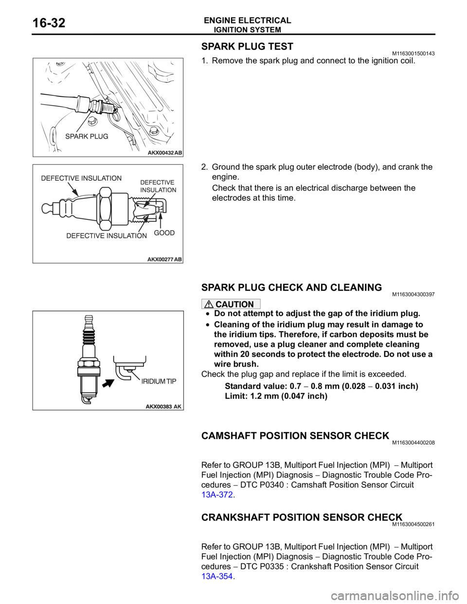
SPARK PLUG TESTM1163001500143
1. Remove the spark plug and connect to the ignition coil.
2. Ground the spark plug outer electrode (body), and crank the
engine.
Check that there is an electrical discharge between the
electrodes at this time.
SPARK PLUG CHECK AND CLEANING M1163004300397
Do not attempt to adjust the gap of the iridium plug.
Cleaning of the iridium plug may result in damage to
the iridium tips. Therefore, if carbon deposits must be
removed, use a plug cleaner and complete cleaning
within 20 seconds to protect the electrode. Do not use a
wire brush.
Check the plug gap and replace if the limit is exceeded.
Standard value: 0.7
0.8 mm (0.028 0.031 inch)
Limit: 1.2 mm (0.047 inch)
CAMSHAFT POSITION SENSOR CHECKM1163004400208
Refer to GROUP 13B, Multiport Fuel Injection (MPI) Multiport
Fuel Injection (MPI) Diagnosis
Diagnostic Trouble Code Pro-
cedures
DTC P0340 : Camshaft Position Sensor Circuit
13A-372.
CRANKSHAFT POSITION SENSOR CHECKM1163004500261
Refer to GROUP 13B, Multiport Fuel Injection (MPI) Multiport
Fuel Injection (MPI) Diagnosis
Diagnostic Trouble Code Pro-
cedures
DTC P0335 : Crankshaft Position Sensor Circuit
13A-354.
Page 1026 of 1500
CROSSMEMBER
POWER PLANT MOUNT32-9
CROSSMEMBER
REMOVAL AND INSTALLATIONM1321003200551
Before removing the steering wheel and air bag module assembly, always refer to GROUP 52B -
Service Precautions (P.52B-16), Air bag Module and Clock Spring (P.52B-237). Also, set the front
wheels so that they are facing straight forward, and remove the ignition key. If you fail to do this,
the SRS clock spring will be damaged, causing the SRS air bag to be inoperative and serious
injury.
*1: Indicates parts which should be initially tightened, and then fully tightened after placing the
vehicle horizontally and loading the full weight of the engine on the vehicle body.
*2: Indicates parts which should be temporarily tightened, and then fully tightened with the vehicle
on the ground in the unladen condition.
Pre-removal Operation
Power Steering Fluid Draining (Refer to GROUP 37,
On-vehicle Service Fluid Replacement P.37-18).
Power Steering Hoses Removal and Installation (Refer to
GROUP 37, Power Steering Hoses P.37A-57).
Air Bag Module and Steering Wheel Assembly Removal
(Refer to GROUP 37, Steering Wheel P.37-23).
Clock Spring Removal (Refer to GROUP 52B, Air Bag
Module and Clock Spring P.52B-237).
Floor Console Assembly Removal (Refer to GROUP 52A,
Floor Console Assembly P.52A-10).
Front Scuff Plate (LH) and Cowl Side Trim (LH) Removal
(Refer to GROUP 52A, Trims P.52A-11).
Trunk Lid Release Handle Cover Removal (Refer to
GROUP 42, Trunk Lid P.42-63).
Accelerator Stopper Removal (Refer to GROUP 17,
Accelerator Pedal P.17-9).
Front Floor Carpet Removal
Centremember Removal (Refer to P.32-7).Post-installation Operation
Centremember Installation (Refer to P.32-7).
Front Floor Carpet Installation
Accelerator Stopper Installation (Refer to GROUP 17,
Accelerator Pedal P.17-9).
Trunk Lid Release Handle Cover Installation (Refer to
GROUP 42, Trunk Lid P.42-63).
Front Scuff Plate (LH) and Cowl Side Trim (LH) Installa-
tion (Refer to GROUP 52A, Trims P.52A-11).
Floor Console Assembly Installation (Refer to GROUP
52A, Floor Console Assembly P.52A-10).
Clock Spring Installation (Refer to GROUP 52B, Air Bag
Module and Clock Spring P.52B-237).
Steering Wheel Assembly and Air Bag Module Installation
(Refer to P.37-23).
Check the dust cover for cracks or damage by pushing it
with your finger.
Power Steering Fluid Supplying (Refer to GROUP 37,
On-vehicle Service Fluid Replacement P.37-18).
Power Steering Fluid Line Bleeding (Refer to P.37-18).
Checking Steering Wheel Position with Wheels Straight
Ahead.
Front Wheel Alignment Adjustment (Refer to GROUP 33,
On-vehicle Service
Front Wheel Alignment Check and
Adjustment P.33-6).
Page 1169 of 1500
BASIC BRAKE SYSTEM DIAGNOSIS
BASIC BRAKE SYSTEM35A-4
STEP 2. Check disc brake pistons for smooth
operation.
(1) With engine not running, depress the brake pedal
rapidly several times to deplete booster vacuum
reserves.
(2) Test each disc brake assembly one at a time.
a. Remove the lower caliper bolt, then remove
caliper from mount.
b. Have an assistant slowly depress the brake
pedal. Confirm piston(s) extend slowly and
smoothly with no jumpiness. Repeat for each
disc brake assembly.
Q: Do (does) the piston(s) move correctly?
YES :
Go to Step 3.
NO : Disassemble and inspect the brake
assembly (Front: refer to P.35A-33, Rear:
refer to P.35A-36). Then go to Step 5.
STEP 3. Check brake disc(s) for runout.
Refer to P.35A-19.
Q: Is runout outside of specifications?
YES :
Repair or replace the brake disc(s) as
necessary. Then go to Step 5.
NO : Go to Step 4.
STEP 4. Check brake discs for correct thickness.
Refer to P.35A-19.
Q: Is the thickness outside of specifications?
YES :
Repair or replace the brake disc(s) as
necessary. Then go to Step 5.
NO : Perform the brake line bleeding. Then go to
St e p 5.
STEP 5. Retest the system.
Q: Is the symptom eliminated?
YES :
The procedure is complete.
NO : Start over at Step 1. If a new symptom
appears, refer to the appropriate symptom
chart.
INSPECTION PROCEDURE 2: Insufficient Braking Power
.
DIAGNOSIS
STEP 1. Check that the specified brake fluid is
used, its level is correct, and no contamination is
found.
Q: Is there a fault?
YES :
Refill or replace with the specified brake
fluid DOT 3 or DOT 4. Bleed the brakes if
necessary (Refer to P.35A-16). Then go to
Step 7.
NO : Go to Step 2.
STEP 2. Check for spongy (not firm) brakes.
(1) With engine not running, depress the brake pedal
rapidly several times to deplete the booster
vacuum reserve.
(2) With the brake pedal fully released, depress the
brake pedal slowly until it stops.
(3) With a measuring device (ruler, etc.) next to the
brake pedal, depress the pedal firmly and
measure the distance the pedal traveled.
Q: Is the distance greater than 20 mm (0.8 inch)?
YES :
Bleed the brakes to remove air in the fluid
(Refer to P.35A-16). Then go to Step 7.
NO : Go to Step 3.
STEP 3. Check the brake booster function.
Refer to P.35A-14.
Q: Is there a fault?
YES :
Replace the brake booster. Then go to Step
7.
NO : Go to Step 4.
Page 1170 of 1500
BASIC BRAKE SYSTEM DIAGNOSIS
BASIC BRAKE SYSTEM35A-5
STEP 4. Check for pinched or restricted brake
tube or hose.
Q: Is there a pinched or restricted brake tube or hose?
YES :
Replace that complete section of brake tube
or brake hose. Then go to Step 7.
NO : Go to Step 5.
STEP 5. Check for oil, water, etc., on the pad
contact surfaces of all brakes.
Q: Is oil, water, etc., on the pad contact surface?
YES :
Replace the part and determine the
source/cause of foreign material. Recheck
symptom. Then go to Step 7.
NO : The procedure is complete. If condition
persists for vehicles without ABS, go to Step
6.
STEP 7. Recheck symptom.
Q: Is the symptom eliminated?
YES :
The procedure is complete.
NO : Start over at step 1. If a new symptom
surfaces, refer to the appropriate symptom
chart.
INSPECTION PROCEDURE 3: Increased Pedal Stroke (Reduced Pedal-to-Floor Board Clearance)
.
DIAGNOSIS
STEP 1. Check for spongy (not firm) brakes.
(1) With engine not running, depress the brake pedal
rapidly several times to deplete booster vacuum
reserve.
(2) With the brake pedal fully released, depress the
brake pedal slowly until it stops.
(3) With a measuring device (ruler, etc.) next to the
brake pedal, depress the pedal firmly and
measure the distance the pedal traveled.
Q: Is the distance greater than 20 mm (0.8 inch)?
YES :
Bleed the brakes to remove air in the fluid
(Refer to P.35A-16). Then go to Step 7.
NO : Go to Step 2.
STEP 2. Check the pad for wear.
Refer to P.35A-17.
Q: Is the pad thickness outside of specifications?
YES :
Replace the part. Then go to Step 7.
NO : Go to Step 3.
STEP 3. Check the vacuum hose and check valve
for damage.
Refer to P.35A-15.
Q: Is there a damage?
YES :
Replace the part. Then go to Step 7.
NO : Go to Step 4.
STEP 4. Check the master cylinder function.
Refer to P.35A-23.
Q: Is there a fault?
YES :
Repair it. Then go to Step 7.
NO : Go to Step 5.
STEP 5. Check for brake fluid leaks.
Q: Is there a leak?
YES :
Check the connection for looseness,
corrosion, etc. Clean and repair as
necessary. If leaking in any tube or hose
section, replace the complete tube or hose.
Then go to Step 7 .
NO : Go to Step 6.
STEP 6. Check for excessive clearance between
the push rod and primary piston.
Refer to P.35A-26.
Q: Is the clearance outside of specifications?
YES :
Adjust the clearance. Then go to Step 7.
NO : Go to Step 7.
STEP 7. Recheck symptom.
Q: Is the symptom eliminated?
YES :
The procedure is complete.
NO : Start over at step 1. If a new symptom
surfaces, refer to the symptom chart.
Page 1179 of 1500
ON-VEHICLE SERVICE
BASIC BRAKE SYSTEM35A-14
BRAKE PEDAL FREE PLAY
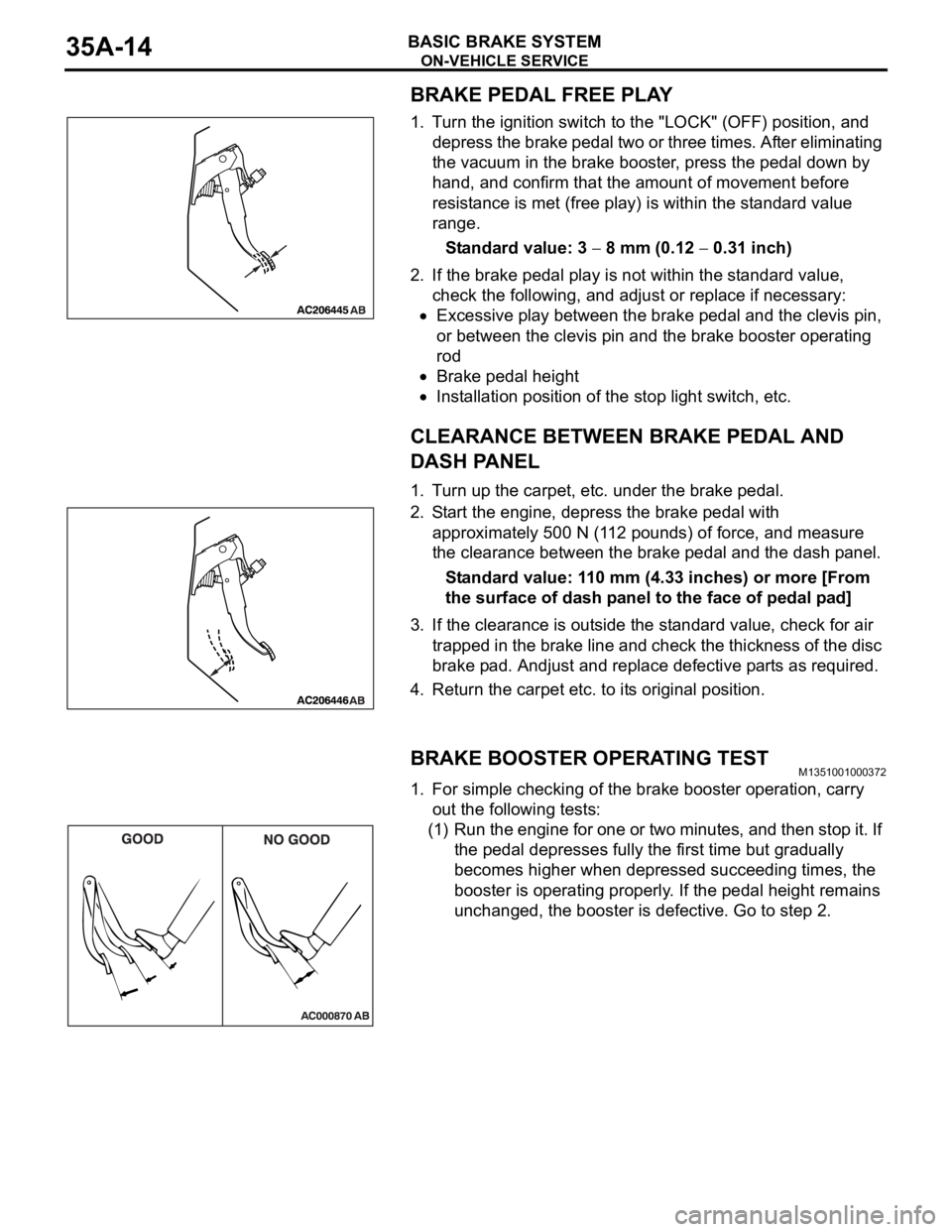
1. Turn the ignition switch to the "LOCK" (OFF) position, and
depress the brake pedal two or three times. After eliminating
the vacuum in the brake booster, press the pedal down by
hand, and confirm that the amount of movement before
resistance is met (free play) is within the standard value
range.
Standard value: 3
8 mm (0.12 0.31 inch)
2. If the brake pedal play is not within the standard value,
check the following, and adjust or replace if necessary:
Excessive play between the brake pedal and the clevis pin,
or between the clevis pin and the brake booster operating
rod
Brake pedal height
Installation position of the stop light switch, etc.
CLEARANCE BETWEEN BRAKE PEDAL AND
DASH PANEL
1. Turn up the carpet, etc. under the brake pedal.
2. Start the engine, depress the brake pedal with
approximately 500 N (112 pounds) of force, and measure
the clearance between the brake pedal and the dash panel.
Standard value: 110 mm (4.33 inches) or more [From
the surface of dash panel to the face of pedal pad]
3. If the clearance is outside the standard value, check for air
trapped in the brake line and check the thickness of the disc
brake pad. Andjust and replace defective parts as required.
4. Return the carpet etc. to its original position.
BRAKE BOOSTER OPERATING TESTM1351001000372
1. For simple checking of the brake booster operation, carry
out the following tests:
(1) Run the engine for one or two minutes, and then stop it. If
the pedal depresses fully the first time but gradually
becomes higher when depressed succeeding times, the
booster is operating properly. If the pedal height remains
unchanged, the booster is defective. Go to step 2.