2005 MERCEDES-BENZ SPRINTER battery
[x] Cancel search: batteryPage 162 of 1232
OPERATION
The heated seat system is designed to provide indi-
vidually controlled, supplemental heat to the seat
cushion and seat back surfaces of both front seats.
Because this system converts electrical current to
heat, the heated seat system can provide a measure
of warm comfort almost immediately upon entering a
cold vehicle, rather than having to wait for the
engine coolant to reach sufficient temperature to
deliver heat through the conventional heater system.
This system allows each front seat occupant to indi-
vidually select one of two comfort levels, Hi or Lo, or
to turn the heater for their seat off.
The heated seat system components operate on
battery current received through a fuse in the Fuse
Block on a fused ignition switch output (run-acc) cir-
cuit so that the system will only operate when theignition switch is in the On or Accessory positions.
The heated seat system will be turned Off automati-
cally whenever the ignition switch is turned to any
position except On or Accessory. Also, the heated seat
system will not operate when the surface tempera-
ture of the seat cushion cover at either heated seat
sensor is above the designed temperature set points
of the system.
DIAGNOSIS AND TESTING - HEATED SEATS
Refer toWiringfor the appropriate wiring infor-
mation. The wiring information includes wiring dia-
grams, proper wire and connector repair procedures,
further details on wire harness routing and reten-
tion, as well as pin-out and location views for the
various wire harness connectors, splices and grounds.
HEATED SEAT SYSTEM DIAGNOSIS
CONDITION POSSIBLE CAUSES CORRECTION
NO HEATED SEAT SWITCH
ILLUMINATION WITH
IGNITION ON1. Faulty fuse. 1. Check heated seat fuse in Fuse Block.
Replace fuse, if required.
2. Wiring faulty. 2. Check fused ignition switch output (run-acc)
circuit from heated seat switch connector to
ignition switch. Repair, if required.
3. Ground faulty. 3. Check for ground at heated seat switch
connector. Repair, if required.
4. Faulty switch. 4. Refer to Heated Seat Switch for the proper
switch diagnosis and testing procedures.
DRIVER HEATED SEAT
SWITCH
DESCRIPTION
The heated seat switches are located on the instru-
ment panel, in the accessory switch bezel. The two,
momentary rocker type switches provide a signal to
the Heated Seat Relay through separate hard wired
circuits. Each switch contains two light emitting
diodes (LED), one for each High and Low setting to
let the occupant know that the seat heater system is
on.
The heated seat switches and their LED's cannot
be repaired. If either switch is faulty or damaged the
entire switch must be replaced.
OPERATION
There are three modes that can be selected with
each of the heated seat switches: Off, Low, and High.
When the top of the switch rocker is depressed, the
low mode is selected and the low mode LED indicator
illuminates. Depressing the top of the switch rocker asecond time will turn the heated seat to Off. This
same process is repeated for High heat setting. The
heated seats will automatically return to the Off
mode anytime the vehicle ignition switch is turned
Off.
Both switches provide separate hard wire inputs to
the Heated Seat Relay to indicate the selected mode.
The Heated Seat Relay responds to the heated seat
switch messages by controlling the output to the seat
heater elements of the selected seat.
DIAGNOSIS AND TESTING - DRIVER HEATED
SEAT SWITCH
For circuit description and diagrams, refer toWir-
ing.
(1) Inspect the Heated Seat Switches for apparent
damage or sticking/binding and replace if required.
Refer to Heated Seat Switch Removal and Installa-
tion in this section.
(2) Replace the heated seat switch with a known
good unit and retest the heated seat system.
8G - 2 HEATED SYSTEMSVA
HEATED SEATS (Continued)
Page 163 of 1232
REMOVAL
(1) Disconnect and isolate the negative battery
cable.
(2) Remove the gear selector bezel trim. Refer to
the Body section for the procedure.
(3) Remove the storage bin. Refer to the Body sec-
tion for the procedure.
(4) Remove the switch bezel retaining screw and
remove the switch bezel from the instrument panel.
Refer to the Body section for the procedure.
(5) Disconnect electrical connections.
(6) Working from the underside of the switch, gen-
tly rock the switch back and forth out of its mounting
location in the switch bezel.
INSTALLATION
(1) Install the heated seat switch in its mounting
location in the switch bezel.
(2) Connect electrical connections.
(3) Position the switch bezel and install the retain-
ing screw. Refer to the Body section for the proce-
dure.
(4) Install the storage bin. Refer to the Body sec-
tion for the procedure.
(5) Install the gear selector bezel trim. Refer to the
Body section for the procedure.
(6) Connect the negative battery cable.
HEATED SEAT ELEMENT
DESCRIPTION
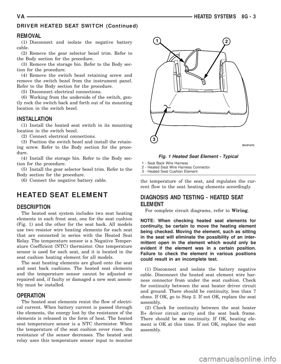
The heated seat system includes two seat heating
elements in each front seat, one for the seat cushion
(Fig. 1) and the other for the seat back. All models
use two resistor wire heating elements for each seat
that are connected in series with the Heated Seat
Relay. The temperature sensor is a Negative Temper-
ature Coefficient (NTC) thermistor. One temperature
sensor is used for each seat, and it is located in the
seat cushion heating element for all models.
The seat heating elements are glued onto the seat
and seat back cushions. The heated seat elements
and the temperature sensor cannot be adjusted or
repaired and, if faulty or damaged a new seat assem-
bly must be installed.
OPERATION
The heated seat elements resist the flow of electri-
cal current. When battery current is passed through
the elements, the energy lost by the resistance of the
elements is released in the form of heat. The heated
seat temperature sensor is a NTC thermistor. When
the temperature of the seat cushion cover rises, the
resistance of the sensor decreases. The heated seat
relay uses this temperature sensor input to monitorthe temperature of the seat, and regulates the cur-
rent flow to the seat heating elements accordingly.
DIAGNOSIS AND TESTING - HEATED SEAT
ELEMENT
For complete circuit diagrams, refer toWiring.
NOTE: When checking heated seat elements for
continuity, be certain to move the heating element
being checked. Moving the element, such as sitting
in the seat will eliminate the possibility of an inter-
mittent open in the element which would only be
evident if the element was in a certain position.
Failure to check the element in various positions
could result in an incomplete test.
(1) Disconnect and isolate the battery negative
cable. Disconnect the heated seat element wire har-
ness connector from under the seat cushion. Check
for continuity between the seat heater driver circuit
and ground. There should be continuity, less than 7
ohms. If OK, go to Step 2. If not OK, replace the seat
assembly.
(2) Check for continuity between the seat heater
B+ driver circuit cavity and the seat back frame.
There should benocontinuity. If OK, heating ele-
ment is OK at this time. If not OK, replace the seat
assembly.
Fig. 1 Heated Seat Element - Typical
1 - Seat Back Wire Harness
2 - Heated Seat Wire Harness Connector
3 - Heated Seat Cushion Element
VAHEATED SYSTEMS 8G - 3
DRIVER HEATED SEAT SWITCH (Continued)
Page 164 of 1232
HEATED SEAT RELAY
DESCRIPTION
The heated seat relay is an electromechanical
device that switches 12v battery current to the
heated seat elements when the relay control coil is
energized. The heated seat relay is located in the
Fuse Block, under the drivers seat. The heated seat
relay is a International Standards Organization
(ISO) relay. Relays conforming to the ISO specifica-
tions have common physical dimensions, current
capacities, terminal patterns, and terminal functions.
The heated seat relay cannot be repaired or
adjusted and, if faulty or damaged, it must be
replaced.
OPERATION
The ISO relay consists of an electromagnetic coil, a
resistor or diode, and three (two fixed and one mov-
able) electrical contacts. The movable (common feed)
relay contact is held against one of the fixed contacts
(normally closed) by spring pressure. When the elec-
tromagnetic coil is energized, it draws the movable
contact away from the normally closed fixed contact,
and holds it against the other (normally open) fixed
contact. When the electromagnetic coil is de-ener-
gized, spring pressure returns the movable contact to
the normally closed position. The resistor or diode is
connected in parallel with the electromagnetic coil in
the relay, and helps to dissipate voltage spikes that
are produced when the coil is de-energized.
DIAGNOSIS AND TESTING - HEATED SEAT
RELAY
The heated seat relay is located in the Fuse Block,
under the drivers seat. Refer toWiringfor the loca-
tion of complete heated seat system wiring diagrams.
(1) Remove the heated seat relay from the fuse
block.
(2) A relay in the de-energized position should
have continuity between terminals 87A and 30, and
no continuity between terminals 87 and 30. If OK, go
to Step 3. If not OK, replace the faulty relay.
(3) Resistance between terminals 85 and 86 (elec-
tromagnet) should be 75 5 ohms. If OK, go to Step
4. If not OK, replace the faulty relay.
(4) Connect a battery to terminals 85 and 86.
There should now be continuity between terminals
30 and 87, and no continuity between terminals 87A
and 30. If OK, check the relay supply circuits. If not
OK, replace the faulty relay.
REMOVAL
(1) Disconnect and isolate the battery negative
cable.
(2) The heated seat relay is located in the fuse
block, under the drivers seat. Refer to wiring for
detailed location.
(3) Grasp the heated seat relay firmly and pull it
straight out from the fuse block. A slight rocking
motion will aid in removal.
INSTALLATION
(1) Grasp the heated seat relay firmly and push it
straight in the fuse block.
(2) Reconnect the battery negative cable.
HEATED SEAT SENSOR
DESCRIPTION
The heated seat temperature sensor is a Negative
Temperature Coefficient (NTC) thermistor. One tem-
perature sensor is used for each seat. The sensor is
located in the seat cushion heating element for all
models.
The heated seat sensor cannot be adjusted or
repaired and if it is found to be faulty, the complete
heated seat element must be replaced.
DIAGNOSIS AND TESTING - HEATED SEAT
SENSOR
For complete circuit diagrams, refer toWiring.
NOTE: Any resistance values (ohmsV) given in the
following text are supplied using the automatic
range generated by a FLUKETautomotive meter. If
another type of measuring device is used the val-
ues generated may not be the same as the results
shown here, or may have to be converted to the
range used here.
(1) Backprobe the heated seat relay wire harness
connector, do not disconnect. Using an voltmeter,
check the voltage of the seat temperature sensor
input cavity of the heated seat relay wire harness
connector. The seat sensor input voltage should be
between 1.7 volts and 3.0 volts with the system ON.
If OK, sensor is OK at this time. If not OK, replace
the faulty seat cushion heating element and sensor
assembly.
8G - 4 HEATED SYSTEMSVA
Page 165 of 1232
PASSENGER HEATED SEAT
SWITCH
DESCRIPTION
The heated seat switches are located on the instru-
ment panel, in the accessory switch bezel. The two,
momentary rocker type switches provide a signal to
the Heated Seat Relay through separate hard wired
circuits. Each switch contains two light emitting
diodes (LED), one for each High and Low setting to
let the occupant know that the seat heater system is
on.
The heated seat switches and their LED's cannot
be repaired. If either switch is faulty or damaged the
entire switch must be replaced.
OPERATION
There are three modes that can be selected with
each of the heated seat switches: Off, Low, and High.
When the top of the switch rocker is depressed, the
low mode is selected and the low mode LED indicator
illuminates. Depressing the top of the switch rocker a
second time will turn the heated seat to Off. This
same process is repeated for High heat setting. The
heated seats will automatically return to the Off
mode anytime the vehicle ignition switch is turned
Off.
Both switches provide separate hard wire inputs to
the Heated Seat Relay to indicate the selected mode.
The Heated Seat Relay responds to the heated seat
switch messages by controlling the output to the seat
heater elements of the selected seat.
DIAGNOSIS AND TESTING - PASSENGER
HEATED SEAT SWITCH
For circuit description and diagrams, refer toWir-
ing.
(1) Inspect the Heated Seat Switches for apparent
damage or sticking/binding and replace if required.
Refer to Heated Seat Switch Removal and Installa-
tion in this section.
(2) Replace the heated seat switch with a known
good unit and retest the heated seat system.
REMOVAL
(1) Disconnect and isolate the negative battery
cable.
(2) Remove the gear selector bezel trim. Refer to
the Body section for the procedure.
(3) Remove the storage bin. Refer to the Body sec-
tion for the procedure.
(4) Remove the switch bezel retaining screw and
remove the switch bezel from the instrument panel.
Refer to the Body section for the procedure.
(5) Disconnect electrical connections.
(6) Working from the underside of the switch, gen-
tly rock the switch back and forth out of its mounting
location in the switch bezel.
INSTALLATION
(1) Install the heated seat switch in its mounting
location in the switch bezel.
(2) Connect electrical connections.
(3) Position the switch bezel and install the retain-
ing screw. Refer to the Body section for the proce-
dure.
(4) Install the storage bin. Refer to the Body sec-
tion for the procedure.
(5) Install the gear selector bezel trim. Refer to the
Body section for the procedure.
(6) Connect the negative battery cable.
VAHEATED SYSTEMS 8G - 5
Page 167 of 1232
HORN
TABLE OF CONTENTS
page page
HORN
REMOVAL.............................1
INSTALLATION..........................1HORN SWITCH
REMOVAL.............................1
INSTALLATION..........................1
HORN
REMOVAL
(1) Disconnect and isolate the battery negative
cable.
(2) Disconnect the wire harness connectors.
(3) Remove the mounting fastener and horns.
INSTALLATION
(1) Position horns and install mounting fasteners.
(2) Connect wire harness connector.
(3) Connect battery negative cable.
HORN SWITCH
REMOVAL
(1) Disconnect and isolate the battery negative
cable.(2) Remove the drivers side airbag (Refer to 8 -
ELECTRICAL/RESTRAINTS/DRIVER AIRBAG -
REMOVAL).
(3) Remove the electrical harness connector.
(4) Remove the mounting fasteners and horn
switch.
INSTALLATION
(1) Connect the wire harness connector.
(2) Position the horn switch and install the mount-
ing fasteners.
(3) Install the drivers side airbag (Refer to 8 -
ELECTRICAL/RESTRAINTS/DRIVER AIRBAG -
INSTALLATION).
(4) Connect the battery negative cable.
VAHORN 8H - 1
Page 169 of 1232
IGNITION CONTROL
TABLE OF CONTENTS
page page
IGNITION CONTROL
SPECIAL TOOLS........................1
GLOW PLUG
REMOVAL.............................1
INSTALLATION..........................1GLOW PLUG RELAY
DESCRIPTION..........................2
OPERATION............................2
DIAGNOSIS AND TESTING - GLOW PLUG
RELAYS..............................2
IGNITION CONTROL
SPECIAL TOOLS
GLOW PLUG
REMOVAL
(1) Disconnect the negative battery cable.
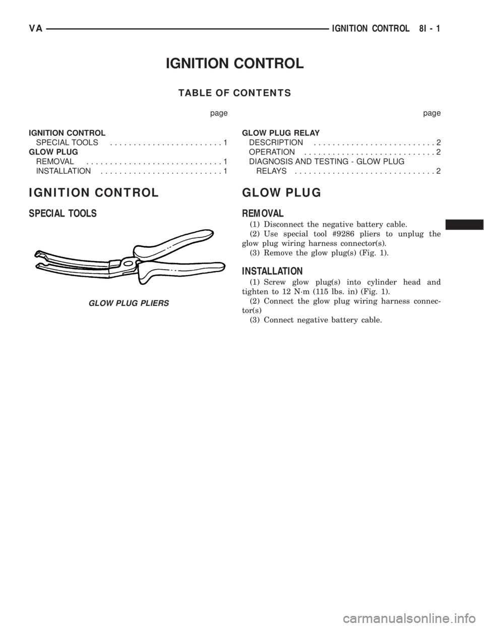
(2) Use special tool #9286 pliers to unplug the
glow plug wiring harness connector(s).
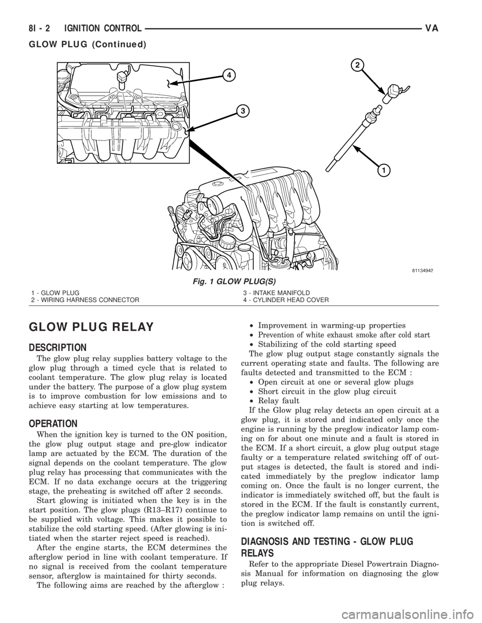
(3) Remove the glow plug(s) (Fig. 1).
INSTALLATION
(1) Screw glow plug(s) into cylinder head and
tighten to 12 N´m (115 lbs. in) (Fig. 1).
(2) Connect the glow plug wiring harness connec-
tor(s)
(3) Connect negative battery cable.
GLOW PLUG PLIERS
VAIGNITION CONTROL 8I - 1
Page 170 of 1232
GLOW PLUG RELAY
DESCRIPTION
The glow plug relay supplies battery voltage to the
glow plug through a timed cycle that is related to
coolant temperature. The glow plug relay is located
under the battery. The purpose of a glow plug system
is to improve combustion for low emissions and to
achieve easy starting at low temperatures.
OPERATION
When the ignition key is turned to the ON position,
the glow plug output stage and pre-glow indicator
lamp are actuated by the ECM. The duration of the
signal depends on the coolant temperature. The glow
plug relay has processing that communicates with the
ECM. If no data exchange occurs at the triggering
stage, the preheating is switched off after 2 seconds.
Start glowing is initiated when the key is in the
start position. The glow plugs (R13±R17) continue to
be supplied with voltage. This makes it possible to
stabilize the cold starting speed. (After glowing is ini-
tiated when the starter reject speed is reached).
After the engine starts, the ECM determines the
afterglow period in line with coolant temperature. If
no signal is received from the coolant temperature
sensor, afterglow is maintained for thirty seconds.
The following aims are reached by the afterglow :²Improvement in warming-up properties
²
Prevention of white exhaust smoke after cold start
²Stabilizing of the cold starting speed
The glow plug output stage constantly signals the
current operating state and faults. The following are
faults detected and transmitted to the ECM :
²Open circuit at one or several glow plugs
²Short circuit in the glow plug circuit
²Relay fault
If the Glow plug relay detects an open circuit at a
glow plug, it is stored and indicated only once the
engine is running by the preglow indicator lamp com-
ing on for about one minute and a fault is stored in
the ECM. If a short circuit, a glow plug output stage
faulty or a temperature related switching off of out-
put stages is detected, the fault is stored and indi-
cated immediately by the preglow indicator lamp
coming on. Once the fault is no longer current, the
indicator is immediately switched off, but the fault is
stored in the ECM. If the fault is constantly current,
the preglow indicator lamp remains on until the igni-
tion is switched off.
DIAGNOSIS AND TESTING - GLOW PLUG
RELAYS
Refer to the appropriate Diesel Powertrain Diagno-
sis Manual for information on diagnosing the glow
plug relays.
Fig. 1 GLOW PLUG(S)
1 - GLOW PLUG
2 - WIRING HARNESS CONNECTOR3 - INTAKE MANIFOLD
4 - CYLINDER HEAD COVER
8I - 2 IGNITION CONTROLVA
GLOW PLUG (Continued)
Page 175 of 1232
The EMIC modules for this model are serviced only
as complete units. The EMIC module cannot be
adjusted or repaired. If a gauge, an LED indicator,
the multi-fuction indicator LCD unit, an electronic
tone generator, the electronic circuit board, the cir-
cuit board hardware, the cluster overlay, the cluster
housing, the cluster hood, the cluster lens, or the
cluster rear cover are damaged or faulty, the entire
EMIC module must be replaced.
OPERATION
The ElectroMechanical Instrument Cluster (EMIC)
is designed to allow the vehicle operator to monitor
the conditions of many of the vehicle components and
operating systems. The gauges, meters and indicators
in the EMIC provide valuable information about the
powertrain, fuel and emissions systems, cooling sys-
tem, lighting systems, safety systems and many
other convenience items. The EMIC is installed in
the instrument panel so that all of these monitors
can be easily viewed by the vehicle operator when
driving, while still allowing relative ease of access for
service. The microprocessor-based EMIC hardware
and software uses various inputs to control the
gauges and indicators visible on the face of the clus-
ter. Some of these inputs are hard wired, but many
are in the form of electronic messages that are trans-
mitted by other electronic modules over the Control-
ler Area Network (CAN) data bus network. (Refer to
8 - ELECTRICAL/ELECTRONIC CONTROL MOD-
ULES/COMMUNICATION - OPERATION).
The EMIC microprocessor smooths the input data
using algorithms to provide gauge readings that are
accurate, stable and responsive to operating condi-
tions. These algorithms are designed to provide
gauge readings during normal operation that are con-
sistent with customer expectations. However, when
abnormal conditions exist such as high coolant tem-
perature, the algorithm can drive the gauge pointer
to an extreme position and the microprocessor can
sound a chime through the on-board audible tone
generator to provide distinct visual and audible indi-
cations of a problem to the vehicle operator. The
instrument cluster circuitry also provides audible
turn signal and hazard warning support by emulat-
ing the ªtickingº sound associated with a conven-
tional electro-mechanical flasher using a contactless
relay. The relay will also provide an indication of a
turn signal failure by sounding at double the usual
frequency. Each audible warning is provided to the
vehicle operator to supplement a visual indication.
The EMIC circuitry operates on battery current
received through a non-switched fused B(+) circuit,
and on a fused ignition switch output circuit. The
EMIC circuitry is grounded through a ground circuit
and take out of the frame wire harness with an eye-let terminal connector that is secured to a stud by a
nut at a ground location on the dash panel just for-
ward of the instrument cluster. Separate switched
ground inputs from the key-in ignition switch and
the front door jamb switches provide wake-up signals
to the EMIC circuitry. This arrangement allows the
EMIC to provide some features regardless of the igni-
tion switch position, while other features will operate
only with the ignition switch in the On position.
Proper diagnosis and testing of the EMIC, the
CAN data bus, the data bus electronic message
inputs to and outputs from the EMIC, as well as the
retrieval or erasure of a Diagnostic Trouble Code
(DTC) requires the use of a DRBIIItscan tool. Refer
to the appropriate diagnostic information. See the
owner's manual in the vehicle glove box for more
information on the features, use and operation of the
EMIC.
GAUGES
All gauges receive battery current through the
EMIC circuitry only when the instrument cluster
detects the ignition switch is in the On position. With
the ignition switch in the Off position, battery cur-
rent is not supplied to any gauges and the EMIC cir-
cuitry is programmed to move all of the gauge
needles back to the low end of their respective scales.
Therefore, the gauges do not accurately indicate any
vehicle condition unless the ignition switch is in the
On position.
All of the EMIC gauges are air core magnetic
units. Two fixed electromagnetic coils are located
within each gauge. These coils are wrapped at right
angles to each other around a movable permanent
magnet. The movable magnet is suspended within
the coils on one end of a pivot shaft, while the gauge
needle is attached to the other end of the shaft. One
of the coils has a fixed current flowing through it to
maintain a constant magnetic field strength. Current
flow through the second coil changes, which causes
changes in its magnetic field strength. The current
flowing through the second coil is changed by the
EMIC circuitry in response to messages received over
the CAN data bus. The gauge needle moves as the
movable permanent magnet aligns itself to the
changing magnetic fields created around it by the
electromagnets.
Proper diagnosis and testing of the gauges, the
CAN data bus and the electronic data bus message
inputs to the EMIC that control each gauge require
the use of a DRBIIItscan tool. Refer to the appro-
priate diagnostic information. Specific operation
details for each gauge may be found elsewhere in
this service information.
VAINSTRUMENT CLUSTER 8J - 5
INSTRUMENT CLUSTER (Continued)