2005 MERCEDES-BENZ SPRINTER transmission oil
[x] Cancel search: transmission oilPage 900 of 1232
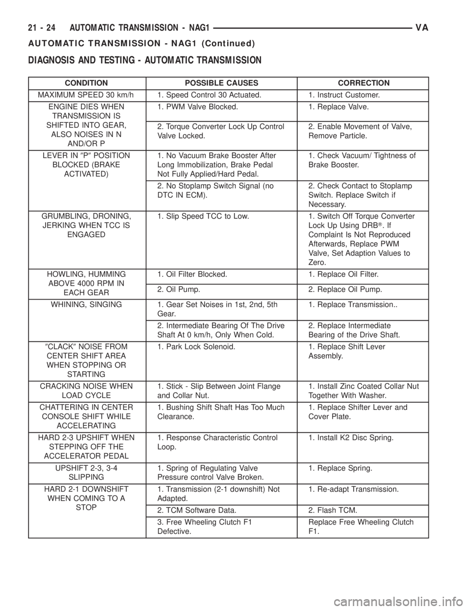
DIAGNOSIS AND TESTING - AUTOMATIC TRANSMISSION
CONDITION POSSIBLE CAUSES CORRECTION
MAXIMUM SPEED 30 km/h 1. Speed Control 30 Actuated. 1. Instruct Customer.
ENGINE DIES WHEN
TRANSMISSION IS
SHIFTED INTO GEAR,
ALSO NOISES IN N
AND/OR P1. PWM Valve Blocked. 1. Replace Valve.
2. Torque Converter Lock Up Control
Valve Locked.2. Enable Movement of Valve,
Remove Particle.
LEVER IN9P9POSITION
BLOCKED (BRAKE
ACTIVATED)1. No Vacuum Brake Booster After
Long Immobilization, Brake Pedal
Not Fully Applied/Hard Pedal.1. Check Vacuum/ Tightness of
Brake Booster.
2. No Stoplamp Switch Signal (no
DTC IN ECM).2. Check Contact to Stoplamp
Switch. Replace Switch if
Necessary.
GRUMBLING, DRONING,
JERKING WHEN TCC IS
ENGAGED1. Slip Speed TCC to Low. 1. Switch Off Torque Converter
Lock Up Using DRBT.If
Complaint Is Not Reproduced
Afterwards, Replace PWM
Valve, Set Adaption Values to
Zero.
HOWLING, HUMMING
ABOVE 4000 RPM IN
EACH GEAR1. Oil Filter Blocked. 1. Replace Oil Filter.
2. Oil Pump. 2. Replace Oil Pump.
WHINING, SINGING 1. Gear Set Noises in 1st, 2nd, 5th
Gear.1. Replace Transmission..
2. Intermediate Bearing Of The Drive
Shaft At 0 km/h, Only When Cold.2. Replace Intermediate
Bearing of the Drive Shaft.
9CLACK9NOISE FROM
CENTER SHIFT AREA
WHEN STOPPING OR
STARTING1. Park Lock Solenoid. 1. Replace Shift Lever
Assembly.
CRACKING NOISE WHEN
LOAD CYCLE1. Stick - Slip Between Joint Flange
and Collar Nut.1. Install Zinc Coated Collar Nut
Together With Washer.
CHATTERING IN CENTER
CONSOLE SHIFT WHILE
ACCELERATING1. Bushing Shift Shaft Has Too Much
Clearance.1. Replace Shifter Lever and
Cover Plate.
HARD 2-3 UPSHIFT WHEN
STEPPING OFF THE
ACCELERATOR PEDAL1. Response Characteristic Control
Loop.1. Install K2 Disc Spring.
UPSHIFT 2-3, 3-4
SLIPPING1. Spring of Regulating Valve
Pressure control Valve Broken.1. Replace Spring.
HARD 2-1 DOWNSHIFT
WHEN COMING TO A
STOP1. Transmission (2-1 downshift) Not
Adapted.1. Re-adapt Transmission.
2. TCM Software Data. 2. Flash TCM.
3. Free Wheeling Clutch F1
Defective.Replace Free Wheeling Clutch
F1.
21 - 24 AUTOMATIC TRANSMISSION - NAG1VA
AUTOMATIC TRANSMISSION - NAG1 (Continued)
Page 901 of 1232
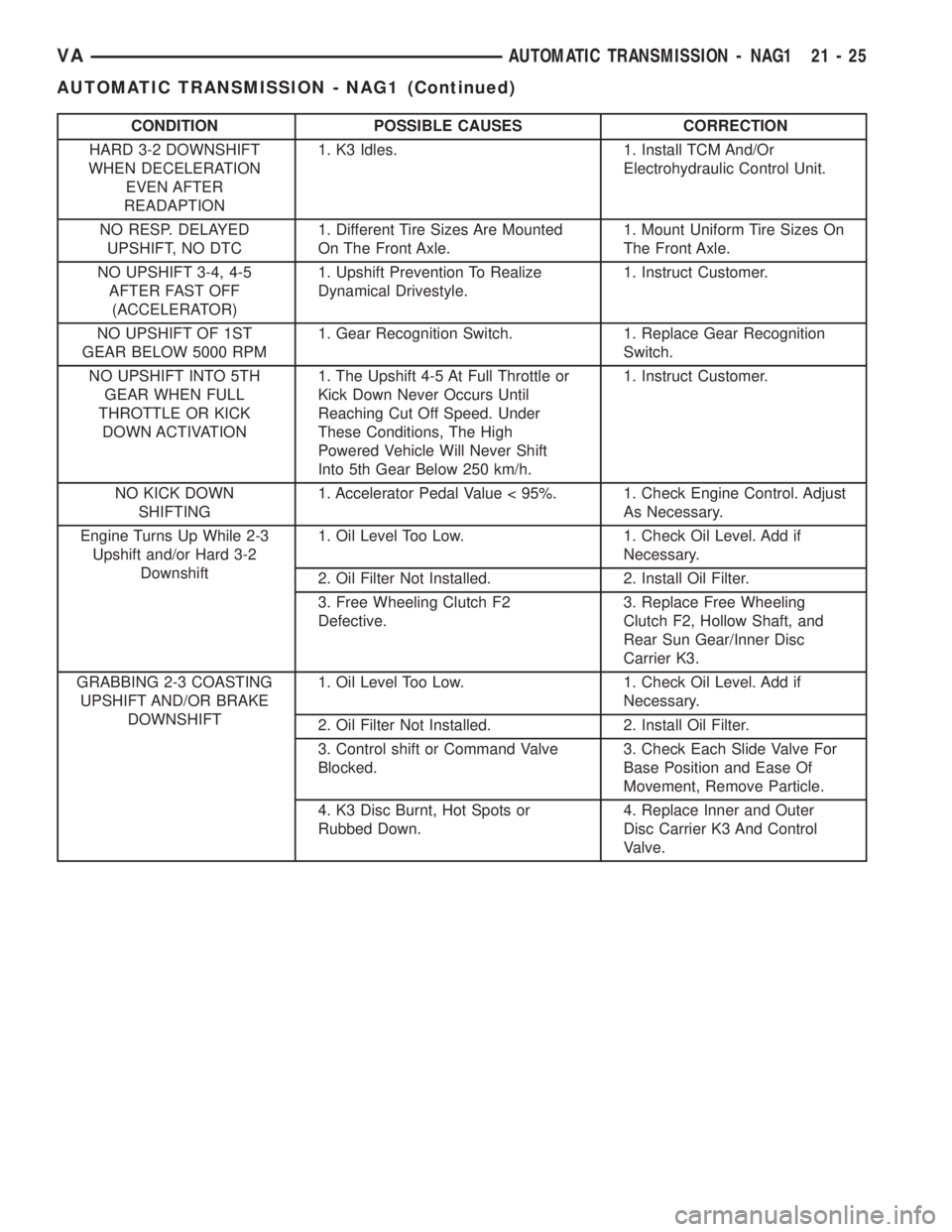
CONDITION POSSIBLE CAUSES CORRECTION
HARD 3-2 DOWNSHIFT
WHEN DECELERATION
EVEN AFTER
READAPTION1. K3 Idles. 1. Install TCM And/Or
Electrohydraulic Control Unit.
NO RESP. DELAYED
UPSHIFT, NO DTC1. Different Tire Sizes Are Mounted
On The Front Axle.1. Mount Uniform Tire Sizes On
The Front Axle.
NO UPSHIFT 3-4, 4-5
AFTER FAST OFF
(ACCELERATOR)1. Upshift Prevention To Realize
Dynamical Drivestyle.1. Instruct Customer.
NO UPSHIFT OF 1ST
GEAR BELOW 5000 RPM1. Gear Recognition Switch. 1. Replace Gear Recognition
Switch.
NO UPSHIFT INTO 5TH
GEAR WHEN FULL
THROTTLE OR KICK
DOWN ACTIVATION1. The Upshift 4-5 At Full Throttle or
Kick Down Never Occurs Until
Reaching Cut Off Speed. Under
These Conditions, The High
Powered Vehicle Will Never Shift
Into 5th Gear Below 250 km/h.1. Instruct Customer.
NO KICK DOWN
SHIFTING1. Accelerator Pedal Value < 95%. 1. Check Engine Control. Adjust
As Necessary.
Engine Turns Up While 2-3
Upshift and/or Hard 3-2
Downshift1. Oil Level Too Low. 1. Check Oil Level. Add if
Necessary.
2. Oil Filter Not Installed. 2. Install Oil Filter.
3. Free Wheeling Clutch F2
Defective.3. Replace Free Wheeling
Clutch F2, Hollow Shaft, and
Rear Sun Gear/Inner Disc
Carrier K3.
GRABBING 2-3 COASTING
UPSHIFT AND/OR BRAKE
DOWNSHIFT1. Oil Level Too Low. 1. Check Oil Level. Add if
Necessary.
2. Oil Filter Not Installed. 2. Install Oil Filter.
3. Control shift or Command Valve
Blocked.3. Check Each Slide Valve For
Base Position and Ease Of
Movement, Remove Particle.
4. K3 Disc Burnt, Hot Spots or
Rubbed Down.4. Replace Inner and Outer
Disc Carrier K3 And Control
Valve.
VAAUTOMATIC TRANSMISSION - NAG1 21 - 25
AUTOMATIC TRANSMISSION - NAG1 (Continued)
Page 902 of 1232
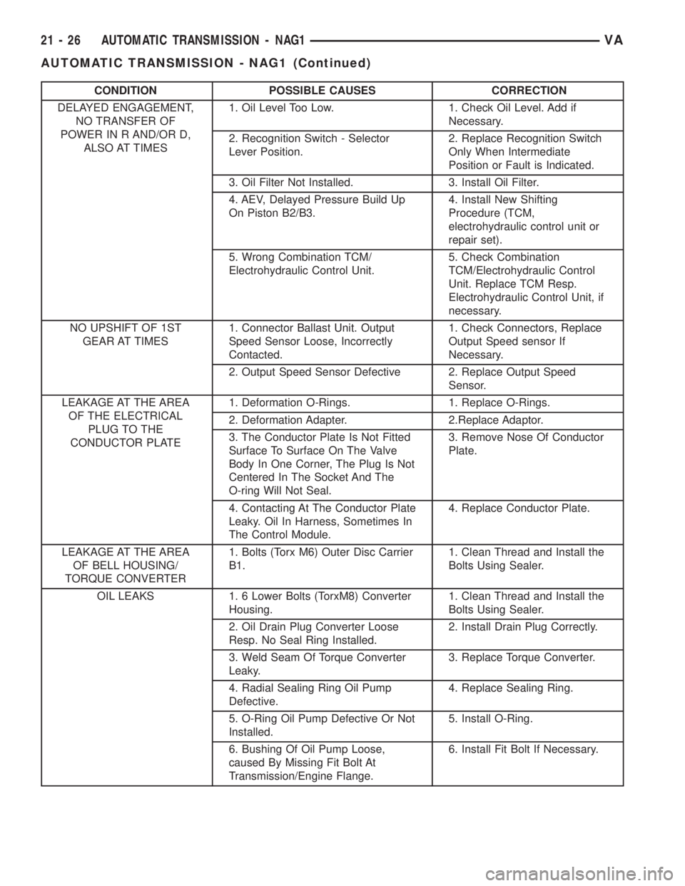
CONDITION POSSIBLE CAUSES CORRECTION
DELAYED ENGAGEMENT,
NO TRANSFER OF
POWER IN R AND/OR D,
ALSO AT TIMES1. Oil Level Too Low. 1. Check Oil Level. Add if
Necessary.
2. Recognition Switch - Selector
Lever Position.2. Replace Recognition Switch
Only When Intermediate
Position or Fault is Indicated.
3. Oil Filter Not Installed. 3. Install Oil Filter.
4. AEV, Delayed Pressure Build Up
On Piston B2/B3.4. Install New Shifting
Procedure (TCM,
electrohydraulic control unit or
repair set).
5. Wrong Combination TCM/
Electrohydraulic Control Unit.5. Check Combination
TCM/Electrohydraulic Control
Unit. Replace TCM Resp.
Electrohydraulic Control Unit, if
necessary.
NO UPSHIFT OF 1ST
GEAR AT TIMES1. Connector Ballast Unit. Output
Speed Sensor Loose, Incorrectly
Contacted.1. Check Connectors, Replace
Output Speed sensor If
Necessary.
2. Output Speed Sensor Defective 2. Replace Output Speed
Sensor.
LEAKAGE AT THE AREA
OF THE ELECTRICAL
PLUG TO THE
CONDUCTOR PLATE1. Deformation O-Rings. 1. Replace O-Rings.
2. Deformation Adapter. 2.Replace Adaptor.
3. The Conductor Plate Is Not Fitted
Surface To Surface On The Valve
Body In One Corner, The Plug Is Not
Centered In The Socket And The
O-ring Will Not Seal.3. Remove Nose Of Conductor
Plate.
4. Contacting At The Conductor Plate
Leaky. Oil In Harness, Sometimes In
The Control Module.4. Replace Conductor Plate.
LEAKAGE AT THE AREA
OF BELL HOUSING/
TORQUE CONVERTER1. Bolts (Torx M6) Outer Disc Carrier
B1.1. Clean Thread and Install the
Bolts Using Sealer.
OIL LEAKS 1. 6 Lower Bolts (TorxM8) Converter
Housing.1. Clean Thread and Install the
Bolts Using Sealer.
2. Oil Drain Plug Converter Loose
Resp. No Seal Ring Installed.2. Install Drain Plug Correctly.
3. Weld Seam Of Torque Converter
Leaky.3. Replace Torque Converter.
4. Radial Sealing Ring Oil Pump
Defective.4. Replace Sealing Ring.
5. O-Ring Oil Pump Defective Or Not
Installed.5. Install O-Ring.
6. Bushing Of Oil Pump Loose,
caused By Missing Fit Bolt At
Transmission/Engine Flange.6. Install Fit Bolt If Necessary.
21 - 26 AUTOMATIC TRANSMISSION - NAG1VA
AUTOMATIC TRANSMISSION - NAG1 (Continued)
Page 903 of 1232
STANDARD PROCEDURE - ALUMINUM
THREAD REPAIR
Damaged or worn threads in the aluminum trans-
mission case and valve body can be repaired by the
use of Heli-CoilsŸ, or equivalent. This repair con-
sists of drilling out the worn-out damaged threads.
Then tap the hole with a special Heli-CoilŸ tap, or
equivalent, and installing a Heli-CoilŸ insert, or
equivalent, into the hole. This brings the hole back to
its original thread size.
Heli-CoilŸ, or equivalent, tools and inserts are
readily available from most automotive parts suppli-
ers.
REMOVAL
(1) Disconnect the negative (ground) battery cable.
CAUTION: Isolate ground lead to prevent accidental
contact.
(2) Apply parking brake.
(3) Move gear selector lever to position9N9.
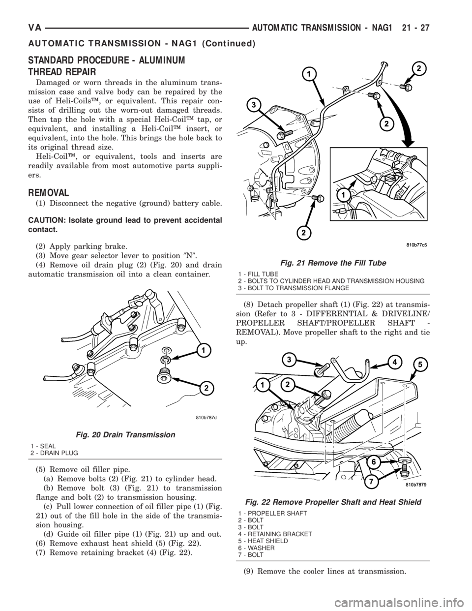
(4) Remove oil drain plug (2) (Fig. 20) and drain
automatic transmission oil into a clean container.
(5) Remove oil filler pipe.
(a) Remove bolts (2) (Fig. 21) to cylinder head.
(b) Remove bolt (3) (Fig. 21) to transmission
flange and bolt (2) to transmission housing.
(c) Pull lower connection of oil filler pipe (1) (Fig.
21) out of the fill hole in the side of the transmis-
sion housing.
(d) Guide oil filler pipe (1) (Fig. 21) up and out.
(6) Remove exhaust heat shield (5) (Fig. 22).
(7) Remove retaining bracket (4) (Fig. 22).(8) Detach propeller shaft (1) (Fig. 22) at transmis-
sion (Refer to 3 - DIFFERENTIAL & DRIVELINE/
PROPELLER SHAFT/PROPELLER SHAFT -
REMOVAL). Move propeller shaft to the right and tie
up.
(9) Remove the cooler lines at transmission.
Fig. 20 Drain Transmission
1 - SEAL
2 - DRAIN PLUG
Fig. 21 Remove the Fill Tube
1 - FILL TUBE
2 - BOLTS TO CYLINDER HEAD AND TRANSMISSION HOUSING
3 - BOLT TO TRANSMISSION FLANGE
Fig. 22 Remove Propeller Shaft and Heat Shield
1 - PROPELLER SHAFT
2 - BOLT
3 - BOLT
4 - RETAINING BRACKET
5 - HEAT SHIELD
6 - WASHER
7 - BOLT
VAAUTOMATIC TRANSMISSION - NAG1 21 - 27
AUTOMATIC TRANSMISSION - NAG1 (Continued)
Page 904 of 1232
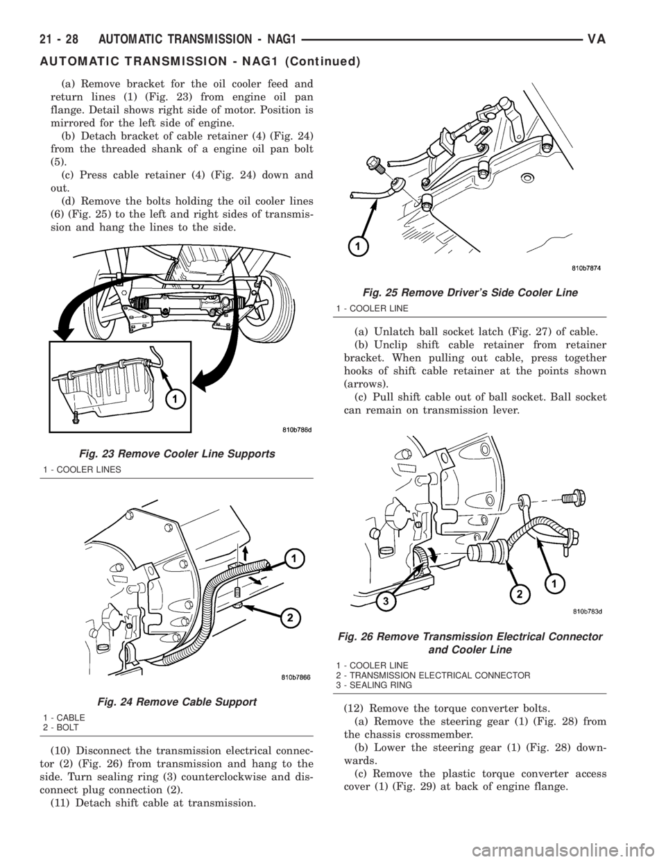
(a) Remove bracket for the oil cooler feed and
return lines (1) (Fig. 23) from engine oil pan
flange. Detail shows right side of motor. Position is
mirrored for the left side of engine.
(b) Detach bracket of cable retainer (4) (Fig. 24)
from the threaded shank of a engine oil pan bolt
(5).
(c) Press cable retainer (4) (Fig. 24) down and
out.
(d) Remove the bolts holding the oil cooler lines
(6) (Fig. 25) to the left and right sides of transmis-
sion and hang the lines to the side.
(10) Disconnect the transmission electrical connec-
tor (2) (Fig. 26) from transmission and hang to the
side. Turn sealing ring (3) counterclockwise and dis-
connect plug connection (2).
(11) Detach shift cable at transmission.(a) Unlatch ball socket latch (Fig. 27) of cable.
(b) Unclip shift cable retainer from retainer
bracket. When pulling out cable, press together
hooks of shift cable retainer at the points shown
(arrows).
(c) Pull shift cable out of ball socket. Ball socket
can remain on transmission lever.
(12) Remove the torque converter bolts.
(a) Remove the steering gear (1) (Fig. 28) from
the chassis crossmember.
(b) Lower the steering gear (1) (Fig. 28) down-
wards.
(c) Remove the plastic torque converter access
cover (1) (Fig. 29) at back of engine flange.
Fig. 23 Remove Cooler Line Supports
1 - COOLER LINES
Fig. 24 Remove Cable Support
1 - CABLE
2 - BOLT
Fig. 25 Remove Driver's Side Cooler Line
1 - COOLER LINE
Fig. 26 Remove Transmission Electrical Connector
and Cooler Line
1 - COOLER LINE
2 - TRANSMISSION ELECTRICAL CONNECTOR
3 - SEALING RING
21 - 28 AUTOMATIC TRANSMISSION - NAG1VA
AUTOMATIC TRANSMISSION - NAG1 (Continued)
Page 905 of 1232
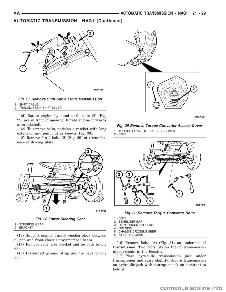
(d) Rotate engine by hand until bolts (2) (Fig.
29) are in front of opening. Rotate engine forwards
at crankshaft.
(e) To remove bolts, position a ratchet with long
extension and joint nut as shown (Fig. 30).
(f) Remove3x2bolts (2) (Fig. 29) at circumfer-
ence of driving plate.
(13) Support engine. Insert wooden block between
oil pan and front chassis crossmember beam.
(14) Remove vent hose bracket and tie back to one
side.
(15) Disconnect ground strap and tie back to one
side.(16) Remove bolts (A) (Fig. 31) on underside of
transmission. Two bolts (A) on top of transmission
must remain in the housing.
(17) Place hydraulic transmission jack under
transmission and raise slightly. Secure transmission
on hydraulic jack with a strap or ask an assistant to
hold it.
Fig. 27 Remove Shift Cable From Transmission
1 - SHIFT CABLE
2 - TRANSMISSION SHIFT LEVER
Fig. 28 Lower Steering Gear
1 - STEERING GEAR
2 - BRACKET
Fig. 29 Remove Torque Converter Access Cover
1 - TORQUE CONVERTER ACCESS COVER
2 - BOLT
Fig. 30 Remove Torque Converter Bolts
1 - BOLT
2 - STABILIZER BAR
3 - REINFORCEMENT PLATE
4 - OPENING
5 - CHASSIS CROSSMEMBER
6 - STEERING GEAR
VAAUTOMATIC TRANSMISSION - NAG1 21 - 29
AUTOMATIC TRANSMISSION - NAG1 (Continued)
Page 906 of 1232
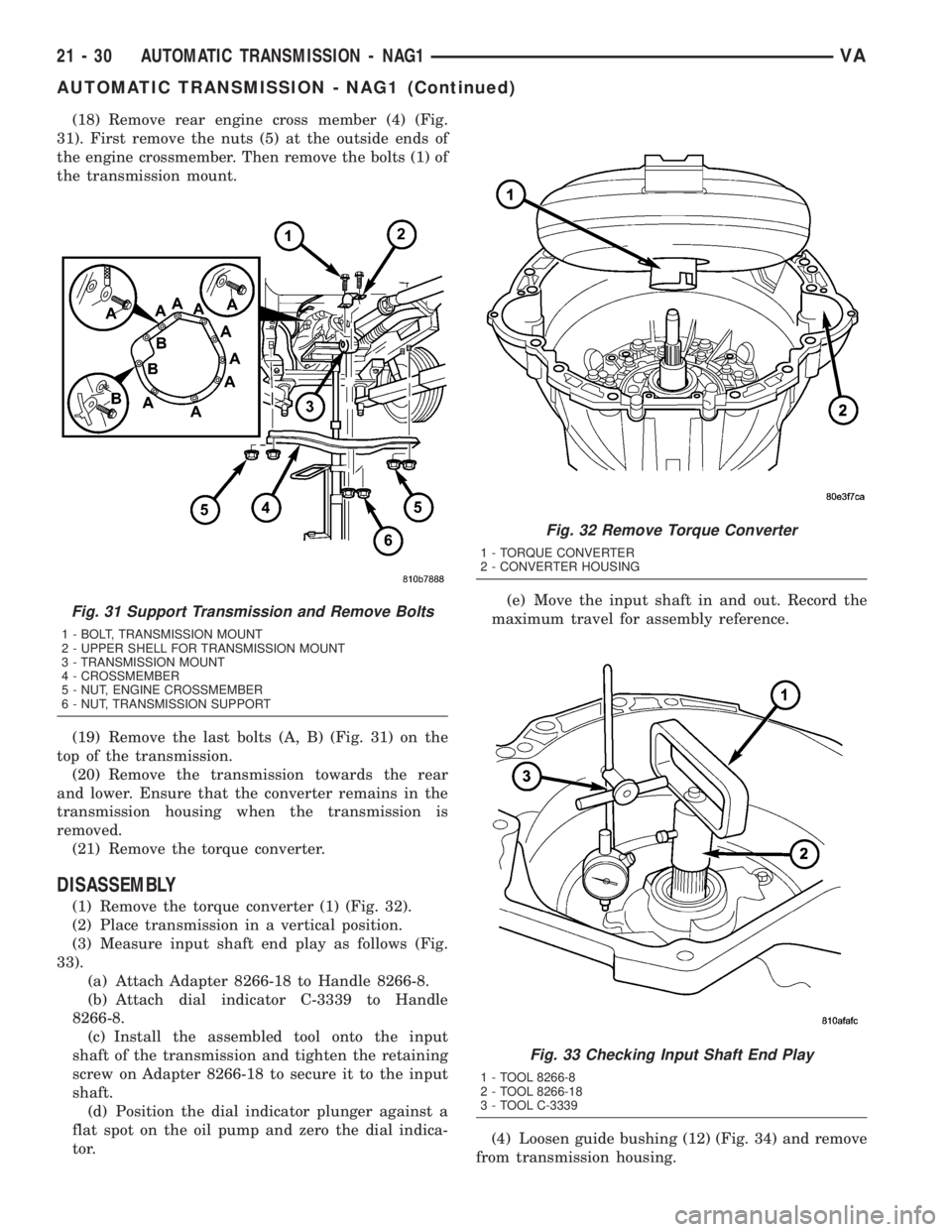
(18) Remove rear engine cross member (4) (Fig.
31). First remove the nuts (5) at the outside ends of
the engine crossmember. Then remove the bolts (1) of
the transmission mount.
(19) Remove the last bolts (A, B) (Fig. 31) on the
top of the transmission.
(20) Remove the transmission towards the rear
and lower. Ensure that the converter remains in the
transmission housing when the transmission is
removed.
(21) Remove the torque converter.
DISASSEMBLY
(1) Remove the torque converter (1) (Fig. 32).
(2) Place transmission in a vertical position.
(3) Measure input shaft end play as follows (Fig.
33).
(a) Attach Adapter 8266-18 to Handle 8266-8.
(b) Attach dial indicator C-3339 to Handle
8266-8.
(c) Install the assembled tool onto the input
shaft of the transmission and tighten the retaining
screw on Adapter 8266-18 to secure it to the input
shaft.
(d) Position the dial indicator plunger against a
flat spot on the oil pump and zero the dial indica-
tor.(e) Move the input shaft in and out. Record the
maximum travel for assembly reference.
(4) Loosen guide bushing (12) (Fig. 34) and remove
from transmission housing.
Fig. 31 Support Transmission and Remove Bolts
1 - BOLT, TRANSMISSION MOUNT
2 - UPPER SHELL FOR TRANSMISSION MOUNT
3 - TRANSMISSION MOUNT
4 - CROSSMEMBER
5 - NUT, ENGINE CROSSMEMBER
6 - NUT, TRANSMISSION SUPPORT
Fig. 32 Remove Torque Converter
1 - TORQUE CONVERTER
2 - CONVERTER HOUSING
Fig. 33 Checking Input Shaft End Play
1 - TOOL 8266-8
2 - TOOL 8266-18
3 - TOOL C-3339
21 - 30 AUTOMATIC TRANSMISSION - NAG1VA
AUTOMATIC TRANSMISSION - NAG1 (Continued)
Page 907 of 1232
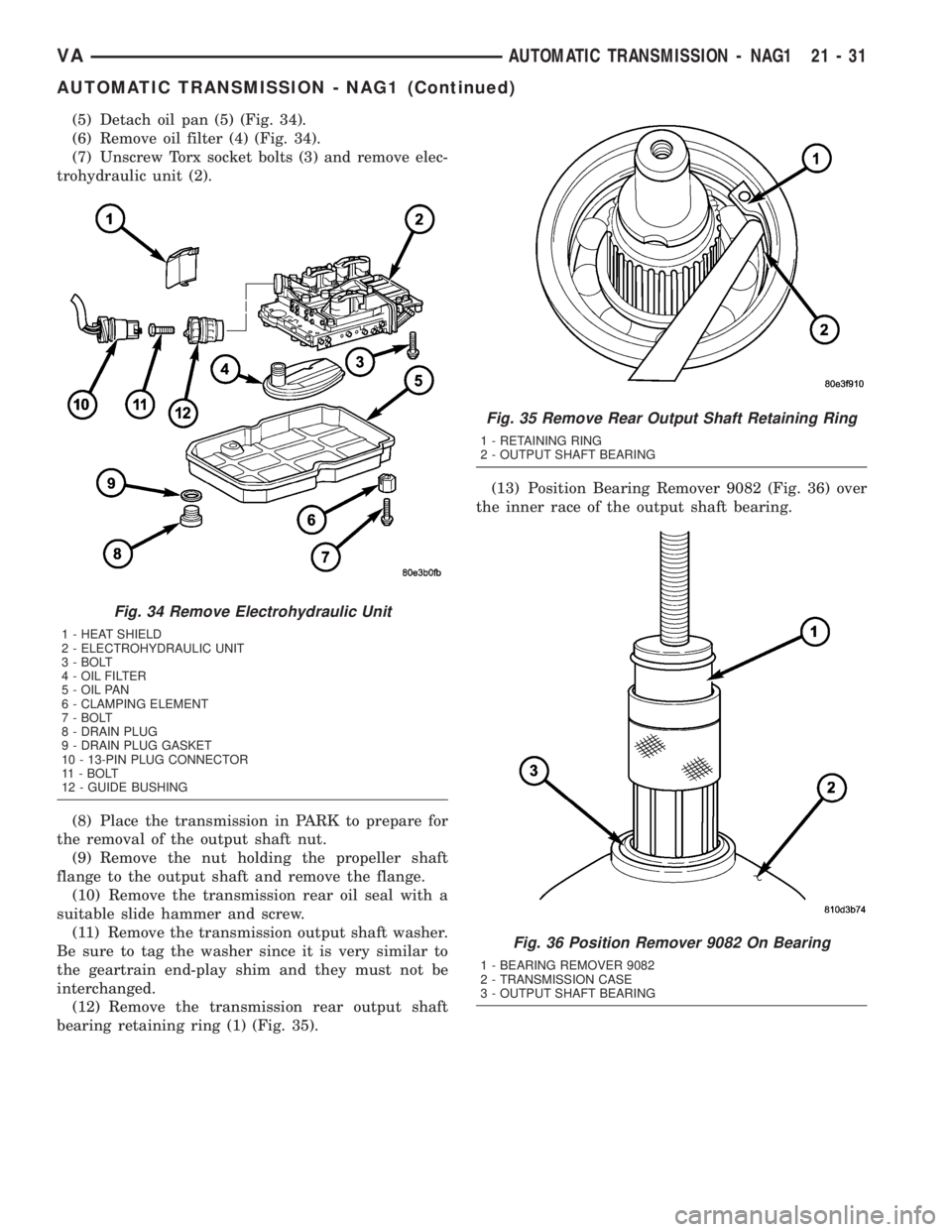
(5) Detach oil pan (5) (Fig. 34).
(6) Remove oil filter (4) (Fig. 34).
(7) Unscrew Torx socket bolts (3) and remove elec-
trohydraulic unit (2).
(8) Place the transmission in PARK to prepare for
the removal of the output shaft nut.
(9) Remove the nut holding the propeller shaft
flange to the output shaft and remove the flange.
(10) Remove the transmission rear oil seal with a
suitable slide hammer and screw.
(11) Remove the transmission output shaft washer.
Be sure to tag the washer since it is very similar to
the geartrain end-play shim and they must not be
interchanged.
(12) Remove the transmission rear output shaft
bearing retaining ring (1) (Fig. 35).(13) Position Bearing Remover 9082 (Fig. 36) over
the inner race of the output shaft bearing.
Fig. 34 Remove Electrohydraulic Unit
1 - HEAT SHIELD
2 - ELECTROHYDRAULIC UNIT
3 - BOLT
4 - OIL FILTER
5 - OIL PAN
6 - CLAMPING ELEMENT
7 - BOLT
8 - DRAIN PLUG
9 - DRAIN PLUG GASKET
10 - 13-PIN PLUG CONNECTOR
11 - BOLT
12 - GUIDE BUSHING
Fig. 35 Remove Rear Output Shaft Retaining Ring
1 - RETAINING RING
2 - OUTPUT SHAFT BEARING
Fig. 36 Position Remover 9082 On Bearing
1 - BEARING REMOVER 9082
2 - TRANSMISSION CASE
3 - OUTPUT SHAFT BEARING
VAAUTOMATIC TRANSMISSION - NAG1 21 - 31
AUTOMATIC TRANSMISSION - NAG1 (Continued)