2005 MERCEDES-BENZ SPRINTER radiator
[x] Cancel search: radiatorPage 1050 of 1232
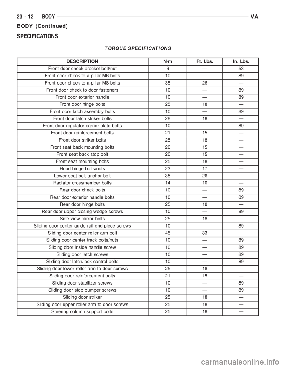
SPECIFICATIONS
TORQUE SPECIFICATIONS
DESCRIPTION N´m Ft. Lbs. In. Lbs.
Front door check bracket bolt/nut 6 Ð 53
Front door check to a-pillar M6 bolts 10 Ð 89
Front door check to a-pillar M8 bolts 35 26 Ð
Front door check to door fasteners 10 Ð 89
Front door exterior handle 10 Ð 89
Front door hinge bolts 25 18 Ð
Front door latch assembly bolts 10 Ð 89
Front door latch striker bolts 28 18 Ð
Front door regulator carrier plate bolts 10 Ð 89
Front door reinforcement bolts 21 15 Ð
Front door striker bolts 25 18 Ð
Front seat back mounting bolts 20 15 Ð
Front seat back stop bolt 20 15 Ð
Front seat mounting bolts 25 18 Ð
Hood hinge bolts/nuts 23 17 Ð
Lower seat belt anchor bolt 35 26 Ð
Radiator crossmember bolts 14 10 Ð
Rear door check bolts 10 Ð 89
Rear door exterior handle bolts 10 Ð 89
Rear door hinge bolts 25 18 Ð
Rear door upper closing wedge screws 10 Ð 89
Side view mirror bolts 25 18 Ð
Sliding door center guide rail end piece screws 10 Ð 89
Sliding door center roller arm bolt 45 33 Ð
Sliding door center track bolts/nuts 10 Ð 89
Sliding door inside handle screw 10 Ð 89
Sliding door latch screws 10 Ð 89
Sliding door latch/lock control bolts 10 Ð 89
Sliding door lower roller arm to door screws 25 18 Ð
Sliding door reinforcement bolts 21 15 Ð
Sliding door stabilizer screws 10 Ð 89
Sliding door stop bumper screws 10 Ð 89
Sliding door striker 25 18 Ð
Sliding door upper roller arm to door screws 25 18 Ð
Steering column support bolts 25 18 Ð
23 - 12 BODYVA
BODY (Continued)
Page 1085 of 1232
EXTERIOR
TABLE OF CONTENTS
page page
FUEL FILL DOOR
REMOVAL.............................47
INSTALLATION.........................47
GRILLE
REMOVAL.............................47
INSTALLATION.........................47
LICENSE PLATE BRACKET
REMOVAL.............................47
INSTALLATION.........................47RADIATOR CROSSMEMBER
REMOVAL.............................47
INSTALLATION.........................48
SIDE VIEW MIRROR
REMOVAL.............................48
INSTALLATION.........................48
SIDE VIEW MIRROR - GLASS
REMOVAL.............................49
INSTALLATION.........................49
FUEL FILL DOOR
REMOVAL
(1) Open passenger compartment door.
(2) Open fuel fill door.
(3) Using a trim stick C-4755 or equivalent, dis-
connect the filler cap tether.
(4) Remove two bolts and remove filler door.
INSTALLATION
(1) Install the door and bolts.
(2) Connect filler cap tether.
(3) Close doors.
GRILLE
REMOVAL
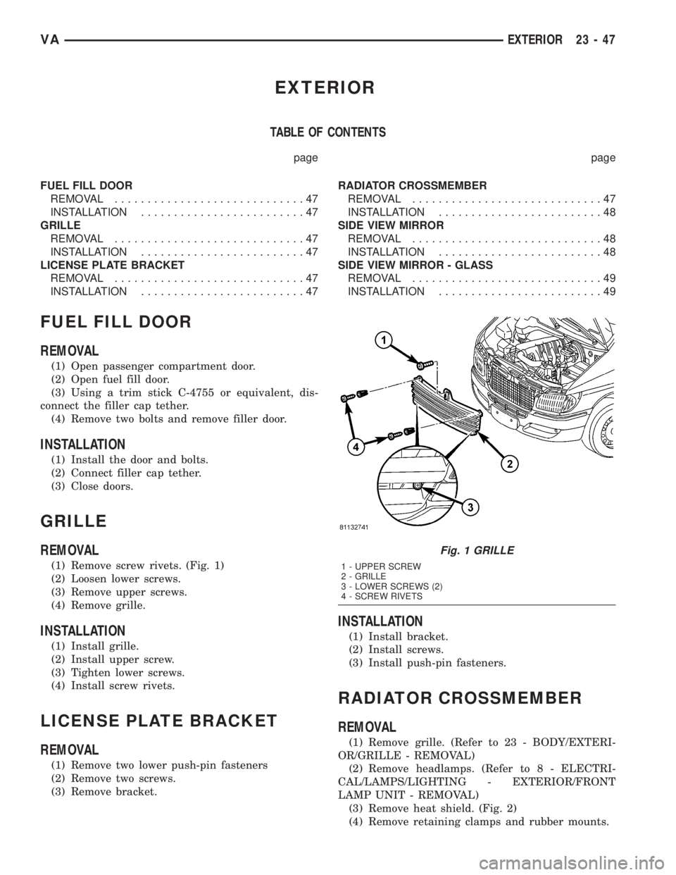
(1) Remove screw rivets. (Fig. 1)
(2) Loosen lower screws.
(3) Remove upper screws.
(4) Remove grille.
INSTALLATION
(1) Install grille.
(2) Install upper screw.
(3) Tighten lower screws.
(4) Install screw rivets.
LICENSE PLATE BRACKET
REMOVAL
(1) Remove two lower push-pin fasteners
(2) Remove two screws.
(3) Remove bracket.
INSTALLATION
(1) Install bracket.
(2) Install screws.
(3) Install push-pin fasteners.
RADIATOR CROSSMEMBER
REMOVAL
(1) Remove grille. (Refer to 23 - BODY/EXTERI-
OR/GRILLE - REMOVAL)
(2) Remove headlamps. (Refer to 8 - ELECTRI-
CAL/LAMPS/LIGHTING - EXTERIOR/FRONT
LAMP UNIT - REMOVAL)
(3) Remove heat shield. (Fig. 2)
(4) Remove retaining clamps and rubber mounts.
Fig. 1 GRILLE
1 - UPPER SCREW
2 - GRILLE
3 - LOWER SCREWS (2)
4 - SCREW RIVETS
VAEXTERIOR 23 - 47
Page 1086 of 1232
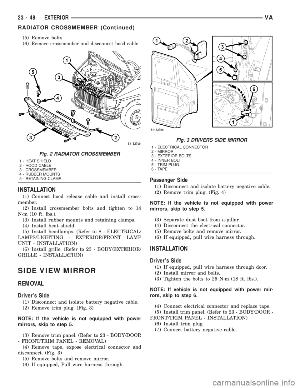
(5) Remove bolts.
(6)
Remove crossmember and disconnect hood cable.
INSTALLATION
(1) Connect hood release cable and install cross-
member.
(2) Install crossmember bolts and tighten to 14
N´m (10 ft. lbs.).
(3) Install rubber mounts and retaining clamps.
(4) Install heat shield.
(5) Install headlamps. (Refer to 8 - ELECTRICAL/
LAMPS/LIGHTING - EXTERIOR/FRONT LAMP
UNIT - INSTALLATION)
(6) Install grille. (Refer to 23 - BODY/EXTERIOR/
GRILLE - INSTALLATION)
SIDE VIEW MIRROR
REMOVAL
Driver's Side
(1) Disconnect and isolate battery negative cable.
(2) Remove trim plug. (Fig. 3)
NOTE: If the vehicle is not equipped with power
mirrors, skip to step 5.
(3) Remove trim panel. (Refer to 23 - BODY/DOOR
- FRONT/TRIM PANEL - REMOVAL)
(4) Remove tape, expose electrical connector and
disconnect. (Fig. 3)
(5) Remove bolts and remove mirror.
(6) If equipped, Pull wire harness through.
Passenger Side
(1) Disconnect and isolate battery negative cable.
(2) Remove trim plug. (Fig. 4)
NOTE: If the vehicle is not equipped with power
mirrors, skip to step 5.
(3) Separate dust boot from a-pillar.
(4) Disconnect the electrical connector.
(5) Remove bolts and remove mirror.
(6) If equipped, pull wire harness through.
INSTALLATION
Driver's Side
(1) If equipped, pull wire harness through door.
(2) Install mirror and bolts.
(3) Tighten the bolts to 25 N´m (18 ft. lbs.).
NOTE: If vehicle is not equipped with power mir-
rors, skip to step 6.
(4) Connect electrical connector and replace tape.
(5) Install trim panel. (Refer to 23 - BODY/DOOR -
FRONT/TRIM PANEL - INSTALLATION)
(6) Install trim plug.
(7) Connect battery negative cable.
Fig. 2 RADIATOR CROSSMEMBER
1 - HEAT SHIELD
2 - HOOD CABLE
3 - CROSSMEMBER
4 - RUBBER MOUNTS
5 - RETAINING CLAMP
Fig. 3 DRIVERS SIDE MIRROR
1 - ELECTRICAL CONNECTOR
2 - MIRROR
3 - EXTERIOR BOLTS
4 - INNER BOLT
5 - TRIM PLUG
6 - TAPE
23 - 48 EXTERIORVA
RADIATOR CROSSMEMBER (Continued)
Page 1129 of 1232
HEATING & AIR CONDITIONING
TABLE OF CONTENTS
page page
HEATING & AIR CONDITIONING
DESCRIPTION
DESCRIPTION - COOLING SYSTEM
REQUIREMENTS.......................1
DESCRIPTION - HEATER AND AIR
CONDITIONER........................1
OPERATION - HEATER AND AIR
CONDITIONER........................2
DIAGNOSIS AND TESTING
DIAGNOSIS AND TESTING - FUNCTION
TEST................................3
DIAGNOSIS AND TESTING - A/C
PERFORMANCE TEST..................3DIAGNOSIS AND TESTING - HEATER
PERFORMANCE.......................4
SPECIFICATIONS
A/C SYSTEM..........................5
CONTROLS - FRONT......................8
CONTROLS - REAR......................22
DISTRIBUTION - FRONT...................31
DISTRIBUTION - REAR....................39
PLUMBING.............................43
CABIN HEATER.........................72
HEATING & AIR
CONDITIONING
DESCRIPTION
DESCRIPTION - COOLING SYSTEM
REQUIREMENTS
To maintain the performance level of the heating-
air conditioning system, the engine cooling system
must be properly maintained. The use of a bug
screen is not recommended. Any obstructions in front
of the radiator or condenser will reduce the perfor-
mance of the air conditioning and engine cooling sys-
tems.
The engine cooling system includes the radiator,
thermostat, heater core, heater hoses and the engine
coolant pump. Refer to Cooling for more information
before opening or attempting any service to the
engine cooling system.
DESCRIPTION - HEATER AND AIR
CONDITIONER
A automatic temperature control (ATC) single zone
type heating-air conditioning system is standard
equipment on this model. A manually controlled rear
air conditioning system is available as a factory-in-
stalled option.
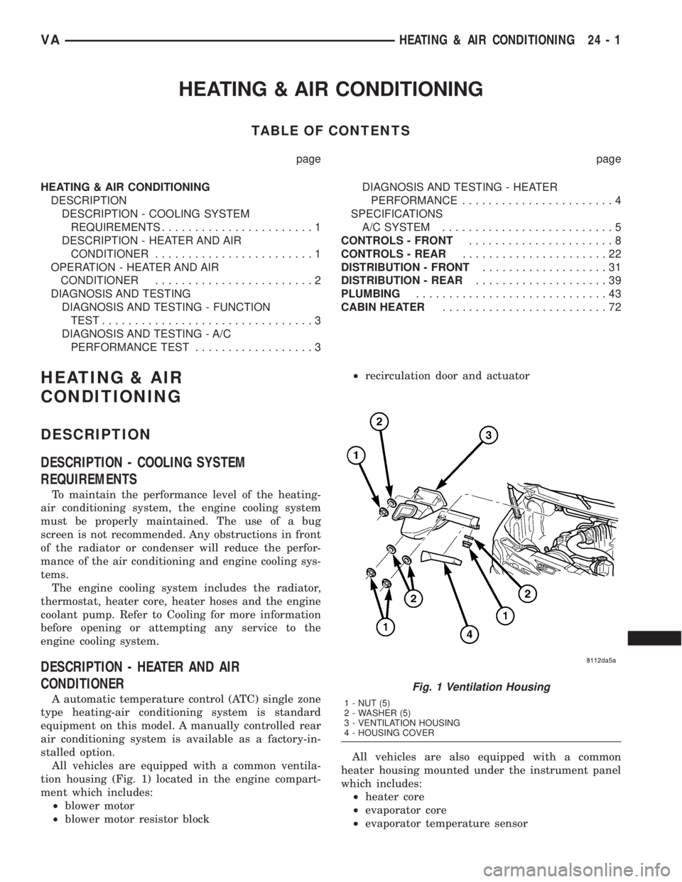
All vehicles are equipped with a common ventila-
tion housing (Fig. 1) located in the engine compart-
ment which includes:
²blower motor
²blower motor resistor block²recirculation door and actuator
All vehicles are also equipped with a common
heater housing mounted under the instrument panel
which includes:
²heater core
²evaporator core
²evaporator temperature sensor
Fig. 1 Ventilation Housing
1 - NUT (5)
2 - WASHER (5)
3 - VENTILATION HOUSING
4 - HOUSING COVER
VAHEATING & AIR CONDITIONING 24 - 1
Page 1132 of 1232
c. With the engine running, duct temperature
should not be less than 2É C (35É F) or than 12É C
(54É F).
(7) If the compressor has not cycled off and the
duct temperature is less than 2É C (35É F) , check the
evaporator temperature sensor and circuit by per-
forming the ATC Function Test (Refer to 24 - HEAT-
ING & AIR CONDITIONING - DIAGNOSIS AND
TESTING).
(8) If duct output temperature is not within speci-
fications, check the refrigerant system for leaks and
proper refrigerant charge (Refer to 24 - HEATING &
AIR CONDITIONING/PLUMBING - DIAGNOSIS
AND TESTING) and (Refer to 24 - HEATING & AIR
CONDITIONING/PLUMBING - STANDARD PRO-
CEDURE).
DIAGNOSIS AND TESTING - HEATER
PERFORMANCE
Before performing the following tests, perform the
ATC Function Test using the DRBIIItand refer toCooling for the procedures to check the radiator cool-
ant level, serpentine drive belt tension, radiator air
flow and the radiator fan operation.
MAXIMUM HEATER OUTPUT
Engine coolant is provided to the heater core
through a heater valve and heater hose. With the
engine idling at normal operating temperature, set
the heater-A/C controls as follows:
²Temperature control in the full hot position
²Mode control in the floor heat position
²Blower motor control in the highest speed posi-
tion
Using a test thermometer, check the temperature
of the air being discharged at the floor outlets. Com-
pare the test thermometer reading to the Tempera-
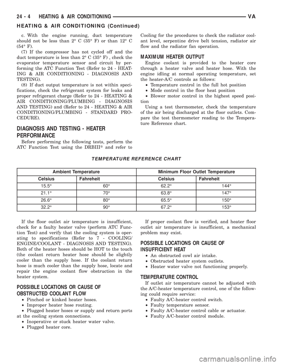
ture Reference chart.
TEMPERATURE REFERENCE CHART
Ambient Temperature Minimum Floor Outlet Temperature
Celsius Fahreheit Celsius Fahreheit
15.5É 60É 62.2É 144É
21.1É 70É 63.8É 147É
26.6É 80É 65.5É 150É
32.2É 90É 67.2É 153É
If the floor outlet air temperature is insufficient,
check for a faulty heater valve (perform ATC Func-
tion Test) and verify that the cooling system is oper-
ating to specifications (Refer to 7 - COOLING/
ENGINE/COOLANT - DIAGNOSIS AND TESTING).
Both of the heater hoses should be HOT to the touch
(the coolant return heater hose should be slightly
cooler than the supply hose. If the coolant return
hose is much cooler than the supply hose, locate and
repair the engine coolant flow obstruction in the
heater system.
POSSIBLE LOCATIONS OR CAUSE OF
OBSTRUCTED COOLANT FLOW
²Pinched or kinked heater hoses.
²Improper heater hose routing.
²Plugged heater hoses or supply and return ports
at the cooling system connections.
²Inoperative or stuck heater water valve.
²Plugged heater core.If proper coolant flow is verified, and heater floor
outlet air temperature is insufficient, a mechanical
problem may exist.
POSSIBLE LOCATIONS OR CAUSE OF
INSUFFICIENT HEAT
²An obstructed cowl air intake.
²Obstructed heater system outlets.
²Heater water valve not functioning properly.
TEMPERATURE CONTROL
If outlet air temperature cannot be adjusted with
the A/C-heater temperature control, one of the follow-
ing could require service:
²Faulty A/C-heater control switch.
²Faulty temperature sensor.
²Faulty A/C-heater control cable or actuator.
²Faulty A/C-heater control module.
24 - 4 HEATING & AIR CONDITIONINGVA
HEATING & AIR CONDITIONING (Continued)
Page 1141 of 1232
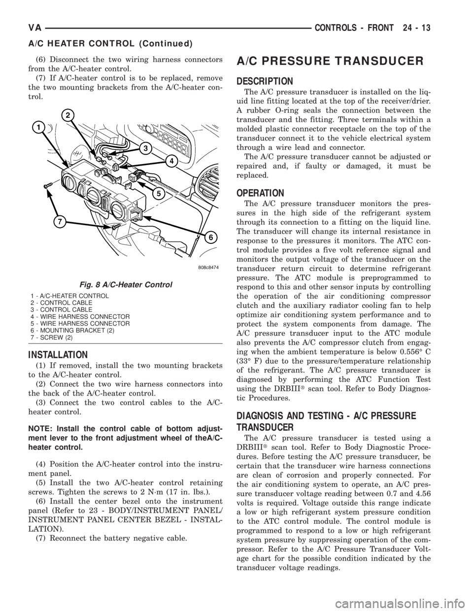
(6) Disconnect the two wiring harness connectors
from the A/C-heater control.
(7) If A/C-heater control is to be replaced, remove
the two mounting brackets from the A/C-heater con-
trol.
INSTALLATION
(1) If removed, install the two mounting brackets
to the A/C-heater control.
(2) Connect the two wire harness connectors into
the back of the A/C-heater control.
(3) Connect the two control cables to the A/C-
heater control.
NOTE: Install the control cable of bottom adjust-
ment lever to the front adjustment wheel of theA/C-
heater control.
(4) Position the A/C-heater control into the instru-
ment panel.
(5) Install the two A/C-heater control retaining
screws. Tighten the screws to 2 N´m (17 in. lbs.).
(6) Install the center bezel onto the instrument
panel (Refer to 23 - BODY/INSTRUMENT PANEL/
INSTRUMENT PANEL CENTER BEZEL - INSTAL-
LATION).
(7) Reconnect the battery negative cable.
A/C PRESSURE TRANSDUCER
DESCRIPTION
The A/C pressure transducer is installed on the liq-
uid line fitting located at the top of the receiver/drier.
A rubber O-ring seals the connection between the
transducer and the fitting. Three terminals within a
molded plastic connector receptacle on the top of the
transducer connect it to the vehicle electrical system
through a wire lead and connector.
The A/C pressure transducer cannot be adjusted or
repaired and, if faulty or damaged, it must be
replaced.
OPERATION
The A/C pressure transducer monitors the pres-
sures in the high side of the refrigerant system
through its connection to a fitting on the liquid line.
The transducer will change its internal resistance in
response to the pressures it monitors. The ATC con-
trol module provides a five volt reference signal and
monitors the output voltage of the transducer on the
transducer return circuit to determine refrigerant
pressure. The ATC module is preprogrammed to
respond to this and other sensor inputs by controlling
the operation of the air conditioning compressor
clutch and the auxiliary radiator cooling fan to help
optimize air conditioning system performance and to
protect the system components from damage. The
A/C pressure transducer input to the ATC module
also prevents the A/C compressor clutch from engag-
ing when the ambient temperature is below 0.556É C
(33É F) due to the pressure/temperature relationship
of the refrigerant. The A/C pressure transducer is
diagnosed by performing the ATC Function Test
using the DRBIIItscan tool. Refer to Body Diagnos-
tic Procedures.
DIAGNOSIS AND TESTING - A/C PRESSURE
TRANSDUCER
The A/C pressure transducer is tested using a
DRBIIItscan tool. Refer to Body Diagnostic Proce-
dures. Before testing the A/C pressure transducer, be
certain that the transducer wire harness connections
are clean of corrosion and properly connected. For
the air conditioning system to operate, an A/C pres-
sure transducer voltage reading between 0.7 and 4.56
volts is required. Voltage outside this range indicate
a low or high refrigerant system pressure condition
to the ATC control module. The control module is
programmed to respond to a low or high refrigerant
system pressure by suppressing operation of the com-
pressor. Refer to the A/C Pressure Transducer Volt-
age chart for the possible condition indicated by the
transducer voltage readings.
Fig. 8 A/C-Heater Control
1 - A/C-HEATER CONTROL
2 - CONTROL CABLE
3 - CONTROL CABLE
4 - WIRE HARNESS CONNECTOR
5 - WIRE HARNESS CONNECTOR
6 - MOUNTING BRACKET (2)
7 - SCREW (2)
VACONTROLS - FRONT 24 - 13
A/C HEATER CONTROL (Continued)
Page 1179 of 1232
INSTALLATION
WARNING: REVIEW THE WARNINGS AND CAU-
TIONS IN THE FRONT OF THIS SECTION BEFORE
PERFORMING THE FOLLOWING OPERATION (Refer
to 24 - HEATING & AIR CONDITIONING/PLUMBING -
WARNING) and (Refer to 24 - HEATING & AIR CON-
DITIONING/PLUMBING - CAUTION).
CAUTION: Check the oil level before installing the
new compressor (Refer to 24 - HEATING & AIR
CONDITIONING/PLUMBING/REFRIGERANT OIL -
STANDARD PROCEDURE).
Any kinks or sharp bends in the refrigerant plumb-
ing will reduce the capacity of the entire air condi-
tioning system. Kinks and sharp bends reduce the
flow of refrigerant in the system. A good rule for the
flexible hose refrigerant lines is to keep the radius of
all bends at least ten times the diameter of the hose.
In addition, the flexible hose refrigerant lines should
be routed so they are at least 80 millimeters (3
inches) from the exhaust manifold.High pressures are produced in the refrigerant sys-
tem when the air conditioning compressor is operat-
ing. Extreme care must be exercised to make sure
that each of the refrigerant system connections is
pressure-tight and leak free. It is a good practice to
inspect all flexible hose refrigerant lines at least once
a year to make sure they are in good condition and
properly routed.
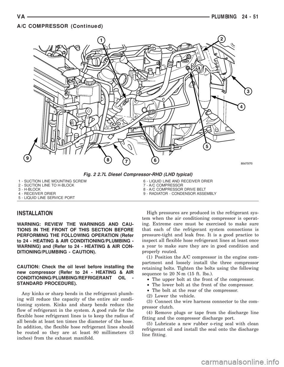
(1) Position the A/C compressor in the engine com-
partment and loosely install the three compressor
retaining bolts. Tighten the bolts using the following
sequence to 20 N´m (15 ft. lbs.).
²The upper bolt at the front of the compressor.
²The lower bolt at the front of the compressor.
²The bolt at the rear of the compressor.
(2) Lower the vehicle.
(3) Connect the wire harness connector to the com-
pressor clutch.
(4) Remove plugs or tape from the discharge line
fitting and the compressor discharge port.
(5) Lubricate a new rubber o-ring seal with clean
refrigerant oil and install the seal onto the discharge
line fitting.
Fig. 2 2.7L Diesel Compressor-RHD (LHD typical)
1 - SUCTION LINE MOUNTING SCREW
2 - SUCTION LINE TO H-BLOCK
3 - H-BLOCK
4 - RECEIVER DRIER
5 - LIQUID LINE SERVICE PORT6 - LIQUID LINE AND RECEIVER DRIER
7 - A/C COMPRESSOR
8 - A/C COMPRESSOR DRIVE BELT
9 - RADIATOR - CONDENSOR ASSEMBLY
VAPLUMBING 24 - 51
A/C COMPRESSOR (Continued)
Page 1180 of 1232
(6) Connect the discharge line fitting to the com-
pressor discharge port.
(7) Install the bolt that secures the discharge line
fitting to the top of the compressor. Tighten the bolt
to 23 N´m (17 ft. lbs.).
(8) Remove plugs or tape from the suction line fit-
ting and the compressor suction port.
(9) Lubricate a new rubber o-ring seal with clean
refrigerant oil and install the seal onto the suction
line fitting.
(10) Connect the suction line fitting to the com-
pressor suction port.
(11) Install the bolt that secures the suction line
fitting to the top of the compressor. Tighten the bolt
to 23 N´m (17 ft. lbs.).
(12) Install the accessory drive belt (Refer to 7 -
COOLING/ACCESSORY DRIVE/DRIVE BELTS -
INSTALLATION).
(13) Reconnect the negative battery cable.
(14) Evacuate the refrigerant system (Refer to 24 -
HEATING & AIR CONDITIONING/PLUMBING -
STANDARD PROCEDURE - REFRIGERANT SYS-
TEM EVACUATE).
(15) Charge the refrigerant system (Refer to 24 -
HEATING & AIR CONDITIONING/PLUMBING -
STANDARD PROCEDURE - REFRIGERANT SYS-
TEM CHARGE).
A/C CONDENSER
DESCRIPTION
The condenser is located in the air flow in front of
the engine cooling radiator. The condenser is a heat
exchanger that allows the high-pressure refrigerant
gas being discharged by the compressor to give up its
heat to the air passing over the condenser fins.
OPERATION
When the refrigerant gas gives up its heat, it con-
denses. When the refrigerant leaves the condenser, it
has become a high-pressure liquid refrigerant. The
volume of air flowing over the condenser fins is crit-
ical to the proper cooling performance of the air con-
ditioning system. Therefore, it is important that
there are no objects placed in front of the radiator
grille openings in the front of the vehicle or foreign
material on the condenser fins that might obstruct
proper air flow. Also, any factory-installed air seals or
shrouds must be properly reinstalled following radia-
tor or condenser service.
The condenser cannot be repaired and, if faulty or
damaged, it must be replaced.
REMOVAL
WARNING: REVIEW THE WARNINGS AND CAU-
TIONS IN THE FRONT OF THIS SECTION BEFORE
PERFORMING THE FOLLOWING OPERATION (Refer
to 24 - HEATING & AIR CONDITIONING/PLUMBING -
WARNING) and (Refer to 24 - HEATING & AIR CON-
DITIONING/PLUMBING - CAUTION).
(1) Disconnect and isolate the battery negative
cable.
(2) Recover the refrigerant from the refrigerant
system (Refer to 24 - HEATING & AIR CONDITION-
ING/PLUMBING - STANDARD PROCEDURE -
REFRIGERANT RECOVERY).
(3) Remove the front fascia.
(4) Remove the grille (Refer to 23 - BODY/EXTE-
RIOR/GRILLE - REMOVAL).
(5) Remove the headlamps from their mounts.
(6) Remove the radiator crossmember (Refer to 23
- BODY/EXTERIOR/RADIATOR CROSSMEMBER -
REMOVAL).
(7) Disconnect the liquid line fitting from the con-
denser outlet port (Fig. 3).
(8) Remove the seal from the liquid line fitting and
discard.
(9) Install plug in, or tape over the opened liquid
line fitting and the condenser outlet port.
(10) Disconnect the discharge line fitting from the
condenser inlet port.
(11) Remove the seal from the discharge line fit-
ting and discard.
(12) Install plug in, or tape over the opened dis-
charge line fitting and the condenser inlet port.
(13) Disconnect the wire harness connector from
the auxiliary fan.
(14) Remove the auxiliary fan and upper bracket
assembly.
(15) Remove the auxiliary fan lower bracket
retainers and bracket.
(16) Remove the four condenser retaining screws.
(17) Carefully remove the condenser from the vehi-
cle.
INSTALLATION
NOTE: If the condenser is being replaced, add 30
milliliters (1 fluid ounce) of refrigerant oil to the
refrigerant system. Use only refrigerant oil of the
type recommended for the compressor in the vehi-
cle.
(1) Carefully position the condenser in the vehicle.
(2) Install the four condenser retaining screws.
Tighten the screws to 2 N´m (17 in. lbs.).
24 - 52 PLUMBINGVA
A/C COMPRESSOR (Continued)