2005 MERCEDES-BENZ SPRINTER wiring
[x] Cancel search: wiringPage 164 of 1232
HEATED SEAT RELAY
DESCRIPTION
The heated seat relay is an electromechanical
device that switches 12v battery current to the
heated seat elements when the relay control coil is
energized. The heated seat relay is located in the
Fuse Block, under the drivers seat. The heated seat
relay is a International Standards Organization
(ISO) relay. Relays conforming to the ISO specifica-
tions have common physical dimensions, current
capacities, terminal patterns, and terminal functions.
The heated seat relay cannot be repaired or
adjusted and, if faulty or damaged, it must be
replaced.
OPERATION
The ISO relay consists of an electromagnetic coil, a
resistor or diode, and three (two fixed and one mov-
able) electrical contacts. The movable (common feed)
relay contact is held against one of the fixed contacts
(normally closed) by spring pressure. When the elec-
tromagnetic coil is energized, it draws the movable
contact away from the normally closed fixed contact,
and holds it against the other (normally open) fixed
contact. When the electromagnetic coil is de-ener-
gized, spring pressure returns the movable contact to
the normally closed position. The resistor or diode is
connected in parallel with the electromagnetic coil in
the relay, and helps to dissipate voltage spikes that
are produced when the coil is de-energized.
DIAGNOSIS AND TESTING - HEATED SEAT
RELAY
The heated seat relay is located in the Fuse Block,
under the drivers seat. Refer toWiringfor the loca-
tion of complete heated seat system wiring diagrams.
(1) Remove the heated seat relay from the fuse
block.
(2) A relay in the de-energized position should
have continuity between terminals 87A and 30, and
no continuity between terminals 87 and 30. If OK, go
to Step 3. If not OK, replace the faulty relay.
(3) Resistance between terminals 85 and 86 (elec-
tromagnet) should be 75 5 ohms. If OK, go to Step
4. If not OK, replace the faulty relay.
(4) Connect a battery to terminals 85 and 86.
There should now be continuity between terminals
30 and 87, and no continuity between terminals 87A
and 30. If OK, check the relay supply circuits. If not
OK, replace the faulty relay.
REMOVAL
(1) Disconnect and isolate the battery negative
cable.
(2) The heated seat relay is located in the fuse
block, under the drivers seat. Refer to wiring for
detailed location.
(3) Grasp the heated seat relay firmly and pull it
straight out from the fuse block. A slight rocking
motion will aid in removal.
INSTALLATION
(1) Grasp the heated seat relay firmly and push it
straight in the fuse block.
(2) Reconnect the battery negative cable.
HEATED SEAT SENSOR
DESCRIPTION
The heated seat temperature sensor is a Negative
Temperature Coefficient (NTC) thermistor. One tem-
perature sensor is used for each seat. The sensor is
located in the seat cushion heating element for all
models.
The heated seat sensor cannot be adjusted or
repaired and if it is found to be faulty, the complete
heated seat element must be replaced.
DIAGNOSIS AND TESTING - HEATED SEAT
SENSOR
For complete circuit diagrams, refer toWiring.
NOTE: Any resistance values (ohmsV) given in the
following text are supplied using the automatic
range generated by a FLUKETautomotive meter. If
another type of measuring device is used the val-
ues generated may not be the same as the results
shown here, or may have to be converted to the
range used here.
(1) Backprobe the heated seat relay wire harness
connector, do not disconnect. Using an voltmeter,
check the voltage of the seat temperature sensor
input cavity of the heated seat relay wire harness
connector. The seat sensor input voltage should be
between 1.7 volts and 3.0 volts with the system ON.
If OK, sensor is OK at this time. If not OK, replace
the faulty seat cushion heating element and sensor
assembly.
8G - 4 HEATED SYSTEMSVA
Page 169 of 1232
IGNITION CONTROL
TABLE OF CONTENTS
page page
IGNITION CONTROL
SPECIAL TOOLS........................1
GLOW PLUG
REMOVAL.............................1
INSTALLATION..........................1GLOW PLUG RELAY
DESCRIPTION..........................2
OPERATION............................2
DIAGNOSIS AND TESTING - GLOW PLUG
RELAYS..............................2
IGNITION CONTROL
SPECIAL TOOLS
GLOW PLUG
REMOVAL
(1) Disconnect the negative battery cable.
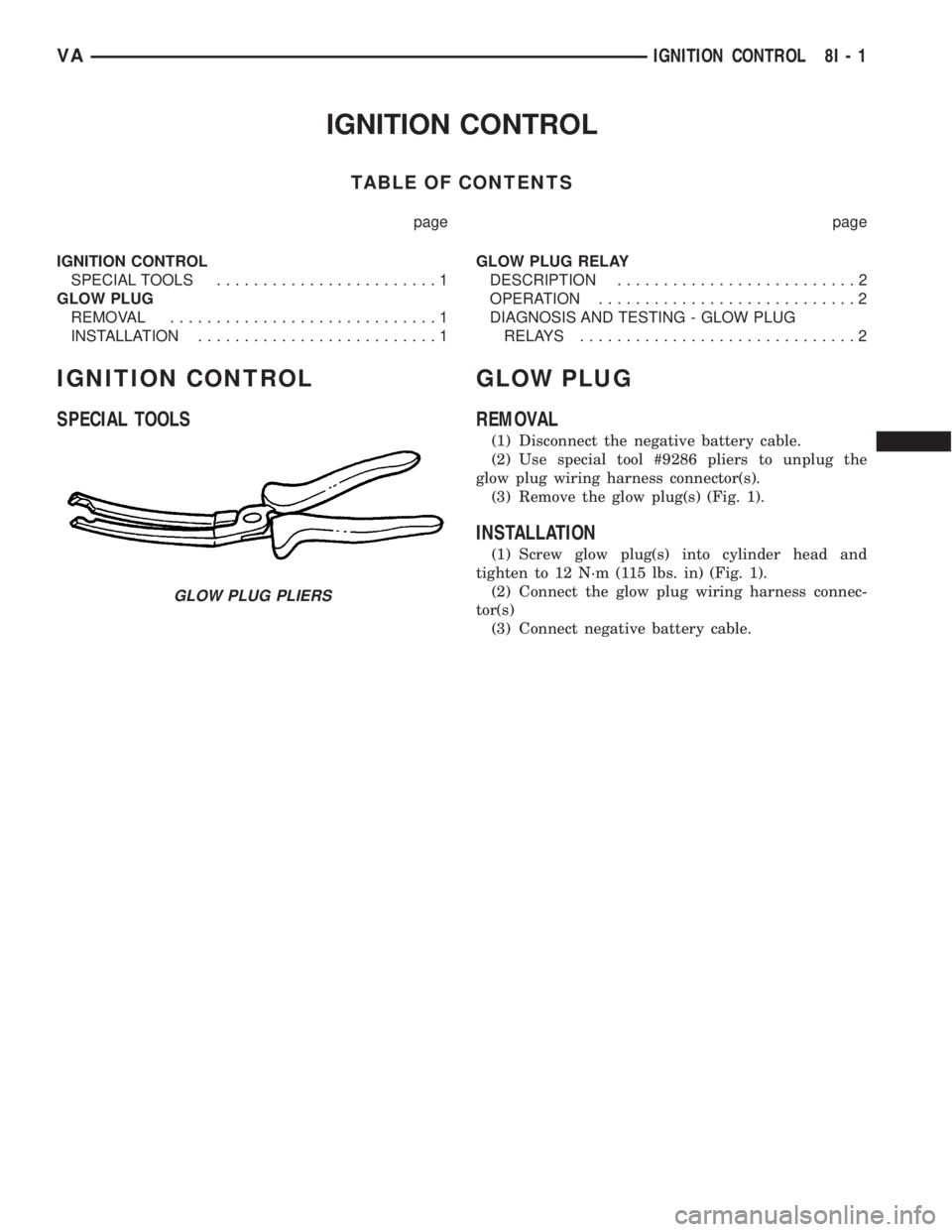
(2) Use special tool #9286 pliers to unplug the
glow plug wiring harness connector(s).
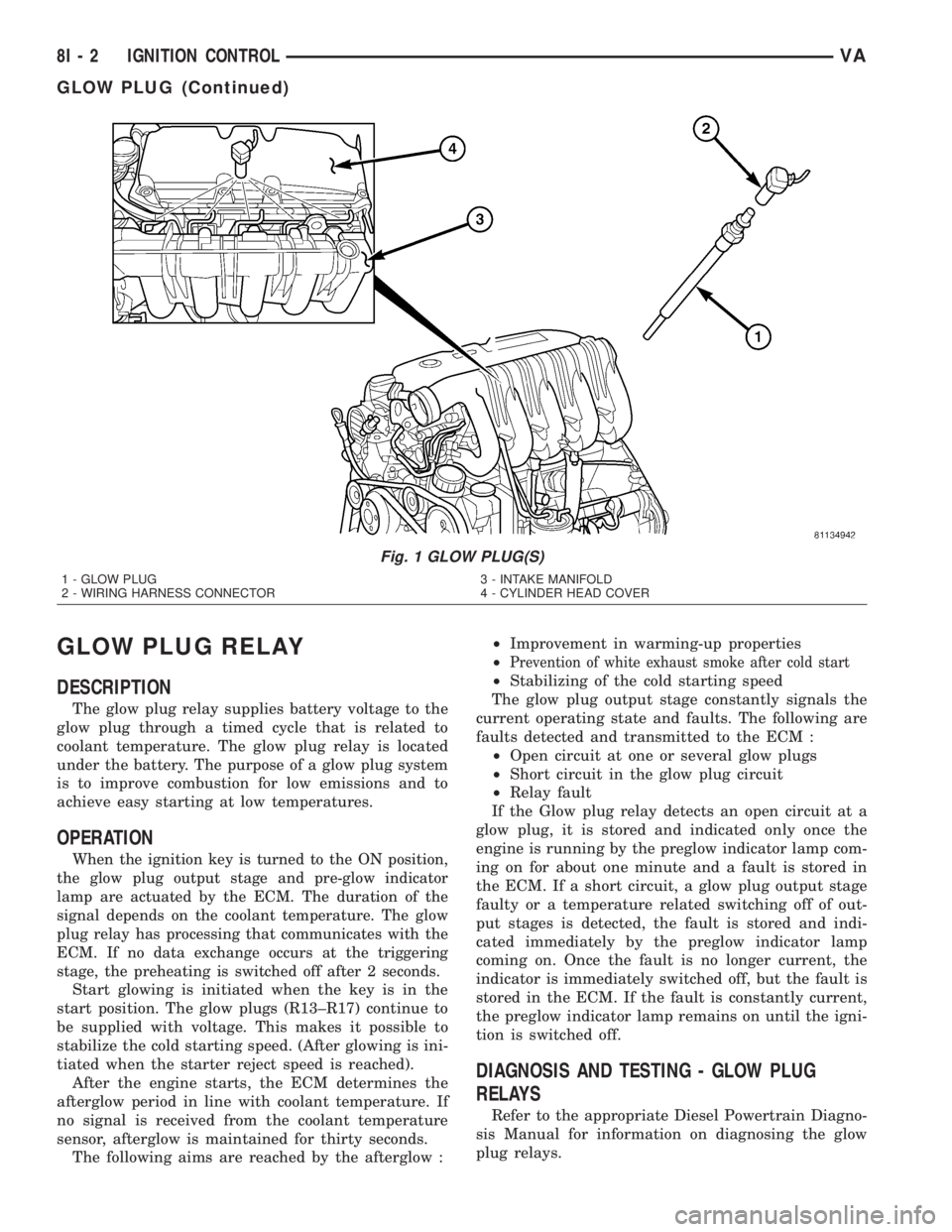
(3) Remove the glow plug(s) (Fig. 1).
INSTALLATION
(1) Screw glow plug(s) into cylinder head and
tighten to 12 N´m (115 lbs. in) (Fig. 1).
(2) Connect the glow plug wiring harness connec-
tor(s)
(3) Connect negative battery cable.
GLOW PLUG PLIERS
VAIGNITION CONTROL 8I - 1
Page 170 of 1232
GLOW PLUG RELAY
DESCRIPTION
The glow plug relay supplies battery voltage to the
glow plug through a timed cycle that is related to
coolant temperature. The glow plug relay is located
under the battery. The purpose of a glow plug system
is to improve combustion for low emissions and to
achieve easy starting at low temperatures.
OPERATION
When the ignition key is turned to the ON position,
the glow plug output stage and pre-glow indicator
lamp are actuated by the ECM. The duration of the
signal depends on the coolant temperature. The glow
plug relay has processing that communicates with the
ECM. If no data exchange occurs at the triggering
stage, the preheating is switched off after 2 seconds.
Start glowing is initiated when the key is in the
start position. The glow plugs (R13±R17) continue to
be supplied with voltage. This makes it possible to
stabilize the cold starting speed. (After glowing is ini-
tiated when the starter reject speed is reached).
After the engine starts, the ECM determines the
afterglow period in line with coolant temperature. If
no signal is received from the coolant temperature
sensor, afterglow is maintained for thirty seconds.
The following aims are reached by the afterglow :²Improvement in warming-up properties
²
Prevention of white exhaust smoke after cold start
²Stabilizing of the cold starting speed
The glow plug output stage constantly signals the
current operating state and faults. The following are
faults detected and transmitted to the ECM :
²Open circuit at one or several glow plugs
²Short circuit in the glow plug circuit
²Relay fault
If the Glow plug relay detects an open circuit at a
glow plug, it is stored and indicated only once the
engine is running by the preglow indicator lamp com-
ing on for about one minute and a fault is stored in
the ECM. If a short circuit, a glow plug output stage
faulty or a temperature related switching off of out-
put stages is detected, the fault is stored and indi-
cated immediately by the preglow indicator lamp
coming on. Once the fault is no longer current, the
indicator is immediately switched off, but the fault is
stored in the ECM. If the fault is constantly current,
the preglow indicator lamp remains on until the igni-
tion is switched off.
DIAGNOSIS AND TESTING - GLOW PLUG
RELAYS
Refer to the appropriate Diesel Powertrain Diagno-
sis Manual for information on diagnosing the glow
plug relays.
Fig. 1 GLOW PLUG(S)
1 - GLOW PLUG
2 - WIRING HARNESS CONNECTOR3 - INTAKE MANIFOLD
4 - CYLINDER HEAD COVER
8I - 2 IGNITION CONTROLVA
GLOW PLUG (Continued)
Page 174 of 1232
Except for the indications provided within the
multi-function indicator LCD unit, each indicator in
the EMIC is illuminated by a dedicated LED that is
soldered onto the EMIC electronic circuit board.
Cluster illumination is accomplished by dimmable
LED back lighting, which illuminates the gauges for
visibility when the exterior lighting is turned on. The
cluster general illumination LED units are also sol-
dered onto the EMIC electronic circuit board. The
LED units are not available for service replacement
and, if damaged or faulty, the entire EMIC must be
replaced.
Hard wired circuitry connects the EMIC to the
electrical system of the vehicle. These hard wired cir-cuits are integral to the vehicle wire harnesses,
which are routed throughout the vehicle and retained
by many different methods. These circuits may be
connected to each other, to the vehicle electrical sys-
tem and to the EMIC through the use of a combina-
tion of soldered splices, splice block connectors, and
many different types of wire harness terminal con-
nectors and insulators. Refer to the appropriate wir-
ing information. The wiring information includes
wiring diagrams, proper wire and connector repair
procedures, further details on wire harness routing
and retention, as well as pin-out and location views
for the various wire harness connectors, splices and
grounds.
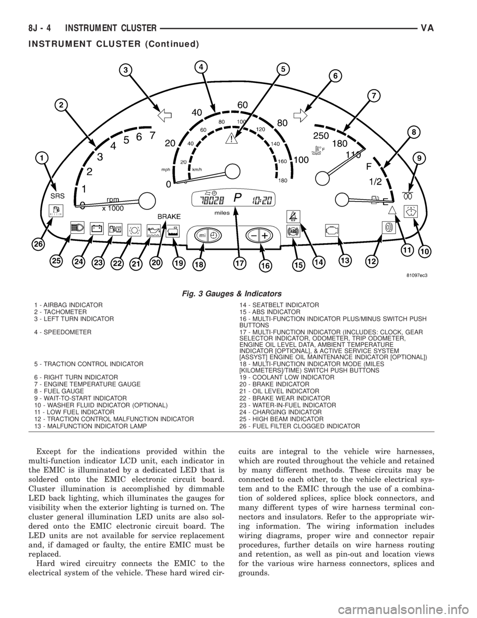
Fig. 3 Gauges & Indicators
1 - AIRBAG INDICATOR 14 - SEATBELT INDICATOR
2 - TACHOMETER 15 - ABS INDICATOR
3 - LEFT TURN INDICATOR 16 - MULTI-FUNCTION INDICATOR PLUS/MINUS SWITCH PUSH
BUTTONS
4 - SPEEDOMETER 17 - MULTI-FUNCTION INDICATOR (INCLUDES: CLOCK, GEAR
SELECTOR INDICATOR, ODOMETER, TRIP ODOMETER,
ENGINE OIL LEVEL DATA, AMBIENT TEMPERATURE
INDICATOR [OPTIONAL], & ACTIVE SERVICE SYSTEM
[ASSYST] ENGINE OIL MAINTENANCE INDICATOR [OPTIONAL])
5 - TRACTION CONTROL INDICATOR 18 - MULTI-FUNCTION INDICATOR MODE (MILES
[KILOMETERS]/TIME) SWITCH PUSH BUTTONS
6 - RIGHT TURN INDICATOR 19 - COOLANT LOW INDICATOR
7 - ENGINE TEMPERATURE GAUGE 20 - BRAKE INDICATOR
8 - FUEL GAUGE 21 - OIL LEVEL INDICATOR
9 - WAIT-TO-START INDICATOR 22 - BRAKE WEAR INDICATOR
10 - WASHER FLUID INDICATOR (OPTIONAL) 23 - WATER-IN-FUEL INDICATOR
11 - LOW FUEL INDICATOR 24 - CHARGING INDICATOR
12 - TRACTION CONTROL MALFUNCTION INDICATOR 25 - HIGH BEAM INDICATOR
13 - MALFUNCTION INDICATOR LAMP 26 - FUEL FILTER CLOGGED INDICATOR
8J - 4 INSTRUMENT CLUSTERVA
INSTRUMENT CLUSTER (Continued)
Page 176 of 1232
INDICATORS
Indicators are located in various positions within
the EMIC and are all connected to the EMIC elec-
tronic circuit board. The ambient temperature indica-
tor (optional), brake indicator, brake wear indicator,
charging indicator, coolant low indicator, high beam
indicator, low fuel indicator, seatbelt indicator, turn
signal indicators, and washer fluid indicator operate
based upon hard wired inputs to the EMIC. The air-
bag (SRS) indicator is normally controlled by a hard
wired input from the Airbag Control Module (ACM);
however, if the EMIC sees an abnormal or no input
from the ACM, it will automatically turn the airbag
indicator On until the hard wired input from the
ACM has been restored. The Malfunction Indicator
Lamp (MIL) is normally controlled by CAN data bus
messages from the Engine Control Module (ECM);
however, if the EMIC loses CAN data bus communi-
cation, the EMIC circuitry will automatically turn
the MIL on until CAN data bus communication is
restored. The EMIC uses CAN data bus messages
from the ECM, the ACM, and the Controller Antilock
Brake to control all of the remaining indicators.
The various EMIC indicators are controlled by dif-
ferent strategies; some receive battery feed from the
EMIC circuitry and have a switched ground, while
others are grounded through the EMIC circuitry and
have a switched battery feed. However, all indicators
are completely controlled by the EMIC microproces-
sor based upon various hard wired and electronic
message inputs. Except for the indications provided
by the multi-function indicator Liquid Crystal Dis-
play (LCD) unit, all indicators are illuminated at a
fixed intensity, which is not affected by the selected
illumination intensity of the EMIC general illumina-
tion lamps.
The hard wired indicator inputs may be diagnosed
using conventional diagnostic methods. However,
proper testing of the EMIC circuitry and the CAN
bus message controlled indicators requires the use of
a DRBIIItscan tool. Refer to the appropriate diag-
nostic information. Specific details of the operation
for each indicator may be found elsewhere in this
service information.
CLUSTER ILLUMINATION
The EMIC has several general illumination lamps
that are illuminated when the exterior lighting is
turned on with the multi-function switch. The illumi-
nation intensity of these lamps is adjusted by a dim-
ming level input received from the multi-function
indicator ª+º (plus) and ª±º (minus) switch push but-
tons that extend through the lower edge of the clus-
ter lens below the right end of the multi-function
indicator. When the exterior lighting is turned Off,
the display is illuminated at maximum brightness.When the exterior lighting is turned On and the
transmission gear selector is in the Park position,
depressing the plus switch push button brightens the
display lighting, and depressing the minus switch
push button dims the display lighting. The EMIC
also provides a Pulse-Width Modulated (PWM) panel
lamps dimmer output that can be used to synchro-
nize the illumination lighting levels of external illu-
mination lamps (up to about 23 to 30 watts) with
that of the EMIC.
The hard wired multi-function switch input and
the EMIC panel lamps dimmer output may be diag-
nosed using conventional diagnostic methods. How-
ever, proper testing of the PWM control of the EMIC
and the electronic dimming level inputs from the
multi-function indicator push buttons requires the
use of a DRBIIItscan tool. Refer to the appropriate
diagnostic information.
INPUT AND OUTPUT CIRCUITS
HARD WIRED INPUTS
The hard wired inputs to the EMIC include the fol-
lowing:
NOTE: Final approved circuit names were not yet
available at the time this information was compiled.
²Airbag Indicator Driver
²Ambient Temperature Sensor Signal
(Optional)
²Brake Wear Indicator Sense
²Charging Indicator Driver
²Coolant Level Switch Sense
²Front Door Jamb Switch Sense
²Fuel Level Sensor Signal
²Fused B(+)
²Fused Ignition Switch Output
²High Beam Indicator Driver
²Key-In Ignition Switch Sense
²Left Turn Signal
²Park Brake Switch Sense
²Right Turn Signal
²Seat Belt Switch Sense
²Washer Fluid Switch Sense (Optional)
Refer to the appropriate wiring information for
additional details.
HARD WIRED OUTPUTS
The hard wired outputs of the EMIC include the
following:
NOTE: Final approved circuit names were not yet
available at the time this information was compiled.
²Engine Running Relay Control
²Panel Lamps Driver
8J - 6 INSTRUMENT CLUSTERVA
INSTRUMENT CLUSTER (Continued)
Page 177 of 1232
Refer to the appropriate wiring information for
additional details.
GROUNDS
The EMIC receives and supplies a ground path to
several switches and sensors through the following
hard wired circuits:
NOTE: Final approved circuit names were not yet
available at the time this information was compiled.
²Ambient Temperature Sensor Return
(Optional)
²Fuel Level Sensor Return
²Ground
Refer to the appropriate wiring information for
additional details.
COMMUNICATION
The EMIC has provisions for the following commu-
nication circuits:
NOTE: Final approved circuit names were not yet
available at the time this information was compiled.
²CAN Data Bus - High
²CAN Data Bus - Low
²Diagnostic Serial Communication Interface
(SCI) Data Bus Line
Refer to the appropriate wiring information for
additional details.
DIAGNOSIS AND TESTING - INSTRUMENT
CLUSTER
The hard wired inputs to and outputs from the
instrument cluster may be diagnosed and tested
using conventional diagnostic tools and procedures.
Refer to the appropriate wiring information. The wir-
ing information includes wiring diagrams, proper
wire and connector repair procedures, details of wire
harness routing and retention, connector pin-out
information and location views for the various wire
harness connectors, splices and grounds.
If the instrument cluster is completely inoperative,
be certain to check the fused B(+) circuit fuses and
wiring for the instrument cluster. If the cluster gen-
eral illumination is inoperative, be certain to check
the instrument lighting fuse and the input circuit to
the instrument cluster from the exterior lighting cir-
cuitry of the multi-function switch on the steering
column.
Conventional diagnostic methods may not prove
conclusive in the diagnosis of the instrument cluster.
In order to obtain conclusive testing of the instru-
ment cluster, the Controller Area Network (CAN)
data bus network and all of the electronic modules
that provide inputs to or receive outputs from theinstrument cluster must also be checked. The most
reliable, efficient, and accurate means to diagnose
the instrument cluster, the CAN data bus network,
and the electronic modules that provide inputs to or
receive outputs from the instrument cluster requires
the use of a DRBIIItscan tool and the appropriate
diagnostic information. The DRBIIItscan tool can
provide confirmation that the CAN data bus network
is functional, that all of the modules are sending and
receiving the proper electronic messages over the
CAN data bus, and that the instrument cluster is
receiving the proper hard wired inputs and respond-
ing with the proper hard wired outputs needed to
perform its many functions.
WARNING: ON VEHICLES EQUIPPED WITH AIR-
BAGS, DISABLE THE SUPPLEMENTAL RESTRAINT
SYSTEM BEFORE ATTEMPTING ANY STEERING
WHEEL, STEERING COLUMN, DRIVER AIRBAG,
PASSENGER AIRBAG, SEAT BELT TENSIONER, OR
INSTRUMENT PANEL COMPONENT DIAGNOSIS OR
SERVICE. DISCONNECT AND ISOLATE THE BAT-
TERY NEGATIVE (GROUND) CABLE, THEN WAIT
TWO MINUTES FOR THE SYSTEM CAPACITOR TO
DISCHARGE BEFORE PERFORMING FURTHER
DIAGNOSIS OR SERVICE. THIS IS THE ONLY SURE
WAY TO DISABLE THE SUPPLEMENTAL
RESTRAINT SYSTEM. FAILURE TO TAKE THE
PROPER PRECAUTIONS COULD RESULT IN ACCI-
DENTAL SUPPLEMENTAL RESTRAINT DEPLOY-
MENT AND POSSIBLE PERSONAL INJURY.
REMOVAL
WARNING: ON VEHICLES EQUIPPED WITH AIR-
BAGS, DISABLE THE SUPPLEMENTAL RESTRAINT
SYSTEM BEFORE ATTEMPTING ANY STEERING
WHEEL, STEERING COLUMN, DRIVER AIRBAG,
PASSENGER AIRBAG, SEAT BELT TENSIONER, OR
INSTRUMENT PANEL COMPONENT DIAGNOSIS OR
SERVICE. DISCONNECT AND ISOLATE THE BAT-
TERY NEGATIVE (GROUND) CABLE, THEN WAIT
TWO MINUTES FOR THE SYSTEM CAPACITOR TO
DISCHARGE BEFORE PERFORMING FURTHER
DIAGNOSIS OR SERVICE. THIS IS THE ONLY SURE
WAY TO DISABLE THE SUPPLEMENTAL
RESTRAINT SYSTEM. FAILURE TO TAKE THE
PROPER PRECAUTIONS COULD RESULT IN ACCI-
DENTAL SUPPLEMENTAL RESTRAINT DEPLOY-
MENT AND POSSIBLE PERSONAL INJURY.
(1) Disconnect and isolate the battery negative
cable.
(2) Remove the cluster bezel from the instrument
panel. (Refer to 23 - BODY/INSTRUMENT PANEL/
CLUSTER BEZEL - REMOVAL).
VAINSTRUMENT CLUSTER 8J - 7
INSTRUMENT CLUSTER (Continued)
Page 201 of 1232
²Trailer Tow Connector- Vehicles equipped
with a factory-approved, field-installed trailer towing
electrical package have a heavy duty 7-way trailer
tow connector installed in a bracket on the trailer
hitch receiver. This package includes a 7-way to
4-way connector adapter unit.
²Trailer Tow Control Module- Vehicles
equipped with a factory-approved, field-installed
trailer towing electrical package have a trailer tow
brake/turn control module located within the driver
side front seat riser that controls the brake lamp and
turn signal lamp outputs to the trailer lighting cir-
cuits.
²Turn Signal Relay- A turn signal relay is
installed in the fuse block located on the underside of
the steering column behind a fuse access panel in the
steering column opening cover on the instrument
panel. The electronic circuitry of the wipers, turn sig-
nals and engine start control module within the fuse
block controls the turn signal relay.
²Wipers, Turn Signals, Engine Start Control
Module- The wipers, turn signals and engine start
control module is integral to the fuse block located on
the underside of the steering column behind a fuse
access panel in the steering column opening cover on
the instrument panel. This module includes active
electronic elements that control the operation of the
turn signal relay based upon inputs from the multi-
function switch and feedback from the turn signal
circuits. (Refer to 8 - ELECTRICAL/POWER DISTRI-
BUTION/FUSE BLOCK - DESCRIPTION).
Hard wired circuitry connects the exterior lighting
system components to the electrical system of the
vehicle. These hard wired circuits are integral to sev-
eral wire harnesses, which are routed throughout the
vehicle and retained by many different methods.
These circuits may be connected to each other, to the
vehicle electrical system and to the exterior lighting
system components through the use of a combination
of soldered splices, splice block connectors, and many
different types of wire harness terminal connectors
and insulators. Refer to the appropriate wiring infor-
mation. The wiring information includes wiring dia-
grams, proper wire and connector repair procedures,
further details on wire harness routing and reten-
tion, as well as pin-out and location views for the
various wire harness connectors, splices and grounds.
OPERATION
Following are paragraphs that briefly describe the
operation of each of the major exterior lighting sys-
tems. The hard wired circuits and components of the
exterior lighting systems may be diagnosed and
tested using conventional diagnostic tools and proce-
dures. However, conventional diagnostic methods
may not prove conclusive in the diagnosis of the wip-ers, turn signals and engine start control module
located within the fuse block underneath the steering
column, the ElectroMechanical Instrument Cluster
(EMIC), the Engine Control Module (ECM), or the
Controller Area Network (CAN) data bus network.
The most reliable, efficient, and accurate means to
diagnose the electronic module within the fuse block,
the EMIC, the ECM, and the CAN data bus network
inputs and outputs related to the various exterior
lighting systems requires the use of a DRBIIItscan
tool. Refer to the appropriate diagnostic information.
BACKUP LAMPS
The backup (or reverse) lamps have a path to
ground received at all times through the vehicle wire
harness from a ground point located on the frame
near the left end of the tailgate sill. The backup
lamps receive battery current on the backup lamp
supply circuit only when the backup lamp switch cir-
cuit of the Transmission Range Sensor (TRS) integral
to the gear shifter assembly is closed by the gear
shifter mechanism.
BRAKE LAMPS
The brake (or stop) lamps have a path to ground at
all times through the vehicle wire harness from a
ground point located on the frame near the left end
of the tailgate sill. The Center High Mounted Stop
Lamp (CHMSL) has a path to ground at all times
through the vehicle wire harness from a ground point
on the left side of the dash panel. The brake lamps
and CHMSL receive battery current on the brake
lamp switch output circuit when the brake lamp
switch is closed by the brake pedal arm.
DAYTIME RUNNING LAMPS
Vehicles manufactured for sale in Canada illumi-
nate the low beam headlamp bulb when the engine is
running and the exterior lamps are turned off. This
feature is enabled by the right and left Daytime Run-
ning Lamps (DRL) relays. When the DRL relays are
de-energized, they provide fused battery current from
the circuit K26 relay to the headlamp low beams.
When the headlamps are turned On using the left
(lighting) control stalk of the multi-function switch
the DRL relays are energized, which returns control
of the headlamps to the headlamp switch circuitry of
the multi-function switch. The circuit K26 relay is
energized by the Electro-Mechanical Instrument
Cluster (EMIC) whenever it receives an electronic
message from the Engine Control Module (ECM) over
the Controller Area Network (CAN) data bus indicat-
ing that the engine is running. The DRL and circuit
K26 relays are installed in a relay bracket located
below the forward edge of the driver side front seat
cushion within the driver side front seat riser.
VALAMPS/LIGHTING - EXTERIOR 8L - 3
LAMPS/LIGHTING - EXTERIOR (Continued)
Page 224 of 1232
A door jamb switch for each sliding side door and the
right rear door is standard equipment on wagon mod-
els. The sliding and rear door jamb switches are not
available for van models.
²Entry/Exit Lamp- An entry/exit lamp to illu-
minate each front and sliding side door step well is
optional equipment on wagon models.
²Time Delay Relay- Vehicles equipped with the
optional remote cargo lamp switches also have a time
delay relay located in the electrical center within the
driver side front seat riser.
Hard wired circuitry connects the interior lighting
system components to the electrical system of the
vehicle. These hard wired circuits are integral to sev-
eral wire harnesses, which are routed throughout the
vehicle and retained by many different methods.
These circuits may be connected to each other, to the
vehicle electrical system and to the interior lighting
system components through the use of a combination
of soldered splices, splice block connectors, and many
different types of wire harness terminal connectors
and insulators. Refer to the appropriate wiring infor-
mation. The wiring information includes wiring dia-
grams, proper wire and connector repair procedures,
further details on wire harness routing and reten-
tion, as well as pin-out and location views for the
various wire harness connectors, splices and grounds.
OPERATION
The interior lighting systems can be divided into
two general classifications based upon the circuit
that controls their operation: The interior lighting
circuit, or the exterior lighting circuit. The hard
wired circuits and components of the interior lighting
systems may be diagnosed and tested using conven-
tional diagnostic tools and procedures.
INTERIOR LIGHTING CIRCUIT
Depending upon the vehicle model (van or wagon)
and the selected vehicle options the interior lighting
circuit may include dome/cargo lamps located over-
head in the front and rear of the vehicle, a dome/
reading lamp located in the header area above the
windshield between the sun visors, and entry/exit
lamps located in the front and sliding side door step
wells.
WAGON MODELS
In all wagon models, the lamps in the interior
lighting circuit are provided with battery current at
all times by a fuse in the fuse block beneath the
steering column. The front, side, and rear door jamb
switches control a ground path for each of these
lamps, except for the optional reading lamp. If the
lamp has an optional integral switch, that switch has
three separate positions. The first position provides aground path independent of the door jamb switches
to turn the lamp On. The second, or center position
allows the door jamb switches to control the lamp.
The third position segregates that lamp from the
door jamb switch input, turning the lamp Off. In the
case of the optional dome/reading lamp, the integral
lamp switch has a fourth position which will illumi-
nate only the reading lamp bulb.
VAN MODELS
Unless a van model is equipped with an optional
remote cargo lamp switch, all of the lamps in the
interior lighting circuit operate the same way as the
wagon models except that there are only two door
jamb switches, one for each front door. If the vehicle
is equipped with an optional remote cargo lamp
switch, the lamps in the rear of the vehicle on the
interior lighting circuit are provided with battery
current by the time delay relay. The time delay relay
is a smart relay containing active electronic elements
that comprise an electronic timer logic circuit. When
the remote cargo lamp switches provide the proper
input to the time delay relay, the relay logic responds
by energizing the relay control coil. The energized
relay control coil provides battery current to all of
the lamps on the rear interior lighting circuit and to
the indicator Light-Emitting Diode (LED) units in
the remote cargo switches causing each to illuminate.
If a remote cargo lamp switch remains On for more
than about fifteen minutes, the time delay relay will
then automatically de-energize the rear interior
lighting circuits until the remote cargo lamp switch
is cycled Off and then back On.
EXTERIOR LIGHTING CIRCUIT
The exterior lighting circuit provides battery cur-
rent to the optional ash receiver/cigar lighter lamp
and to the illumination Light-Emitting Diode (LED)
unit within the remote cargo lamp switch in the
instrument panel accessory switch bezel whenever
the exterior lamps are turned On.
SPECIFICATIONS - INTERIOR LIGHTING
BULB SPECIFICATIONS
LAMP BULB
Cargo/Dome Lamp K - 12V 18W
Dome/Reading Lamp K - 12V 10W
Dome Lamp w/Intrusion
SensorK - 12V 6W
Entry/Exit Lamp W5W - 12V 5W
8L - 26 LAMPS/LIGHTING - INTERIORVA
LAMPS/LIGHTING - INTERIOR (Continued)