2005 MERCEDES-BENZ SPRINTER oil type
[x] Cancel search: oil typePage 224 of 1232
A door jamb switch for each sliding side door and the
right rear door is standard equipment on wagon mod-
els. The sliding and rear door jamb switches are not
available for van models.
²Entry/Exit Lamp- An entry/exit lamp to illu-
minate each front and sliding side door step well is
optional equipment on wagon models.
²Time Delay Relay- Vehicles equipped with the
optional remote cargo lamp switches also have a time
delay relay located in the electrical center within the
driver side front seat riser.
Hard wired circuitry connects the interior lighting
system components to the electrical system of the
vehicle. These hard wired circuits are integral to sev-
eral wire harnesses, which are routed throughout the
vehicle and retained by many different methods.
These circuits may be connected to each other, to the
vehicle electrical system and to the interior lighting
system components through the use of a combination
of soldered splices, splice block connectors, and many
different types of wire harness terminal connectors
and insulators. Refer to the appropriate wiring infor-
mation. The wiring information includes wiring dia-
grams, proper wire and connector repair procedures,
further details on wire harness routing and reten-
tion, as well as pin-out and location views for the
various wire harness connectors, splices and grounds.
OPERATION
The interior lighting systems can be divided into
two general classifications based upon the circuit
that controls their operation: The interior lighting
circuit, or the exterior lighting circuit. The hard
wired circuits and components of the interior lighting
systems may be diagnosed and tested using conven-
tional diagnostic tools and procedures.
INTERIOR LIGHTING CIRCUIT
Depending upon the vehicle model (van or wagon)
and the selected vehicle options the interior lighting
circuit may include dome/cargo lamps located over-
head in the front and rear of the vehicle, a dome/
reading lamp located in the header area above the
windshield between the sun visors, and entry/exit
lamps located in the front and sliding side door step
wells.
WAGON MODELS
In all wagon models, the lamps in the interior
lighting circuit are provided with battery current at
all times by a fuse in the fuse block beneath the
steering column. The front, side, and rear door jamb
switches control a ground path for each of these
lamps, except for the optional reading lamp. If the
lamp has an optional integral switch, that switch has
three separate positions. The first position provides aground path independent of the door jamb switches
to turn the lamp On. The second, or center position
allows the door jamb switches to control the lamp.
The third position segregates that lamp from the
door jamb switch input, turning the lamp Off. In the
case of the optional dome/reading lamp, the integral
lamp switch has a fourth position which will illumi-
nate only the reading lamp bulb.
VAN MODELS
Unless a van model is equipped with an optional
remote cargo lamp switch, all of the lamps in the
interior lighting circuit operate the same way as the
wagon models except that there are only two door
jamb switches, one for each front door. If the vehicle
is equipped with an optional remote cargo lamp
switch, the lamps in the rear of the vehicle on the
interior lighting circuit are provided with battery
current by the time delay relay. The time delay relay
is a smart relay containing active electronic elements
that comprise an electronic timer logic circuit. When
the remote cargo lamp switches provide the proper
input to the time delay relay, the relay logic responds
by energizing the relay control coil. The energized
relay control coil provides battery current to all of
the lamps on the rear interior lighting circuit and to
the indicator Light-Emitting Diode (LED) units in
the remote cargo switches causing each to illuminate.
If a remote cargo lamp switch remains On for more
than about fifteen minutes, the time delay relay will
then automatically de-energize the rear interior
lighting circuits until the remote cargo lamp switch
is cycled Off and then back On.
EXTERIOR LIGHTING CIRCUIT
The exterior lighting circuit provides battery cur-
rent to the optional ash receiver/cigar lighter lamp
and to the illumination Light-Emitting Diode (LED)
unit within the remote cargo lamp switch in the
instrument panel accessory switch bezel whenever
the exterior lamps are turned On.
SPECIFICATIONS - INTERIOR LIGHTING
BULB SPECIFICATIONS
LAMP BULB
Cargo/Dome Lamp K - 12V 18W
Dome/Reading Lamp K - 12V 10W
Dome Lamp w/Intrusion
SensorK - 12V 6W
Entry/Exit Lamp W5W - 12V 5W
8L - 26 LAMPS/LIGHTING - INTERIORVA
LAMPS/LIGHTING - INTERIOR (Continued)
Page 734 of 1232
OPERATION
The cigar lighter consists of two major components:
a knob and heating element unit, and the cigar
lighter base or receptacle shell. The receptacle shell
is connected to ground, and an insulated contact in
the bottom of the shell is connected to battery cur-
rent. The cigar lighter receives battery voltage from a
fuse in the fuseblock only when the ignition switch is
in the Accessory or On positions.
The knob and heating element are encased within
a spring-loaded housing, which also features a sliding
protective heat shield. When the heating element is
inserted in the receptacle shell, the heating element
resistor coil is grounded through its housing to the
receptacle shell. If the cigar lighter knob is pushed
inward, the heat shield slides up toward the knob
exposing the heating element.
Two small spring-clip retainers are located on
either side of the insulated contact inside the bottom
of the receptacle shell. These clips engage and hold
the heating element against the insulated contact
long enough for the resistor coil to heat up and glow.
When the resistor coil becomes sufficiently heated,
excess heat radiates from the heating element caus-
ing the spring-clips to expand. Once the spring-clips
expand far enough to release the heating element,
the spring-loaded housing forces the knob and heat-
ing element to pop back outward to their relaxed
position. When the cigar lighter knob and element
are pulled out of the receptacle shell, the protective
heat shield slides downward on the housing so that
the heating element is recessed and shielded around
its circumference for safety.
DIAGNOSIS AND TESTING - CIGAR LIGHTER
OUTLET
For cigar lighter outlet diagnosis and testing pro-
cedures (Refer to 8 - ELECTRICAL/POWER DISTRI-
BUTION/POWER OUTLET - DIAGNOSIS AND
TESTING)
REMOVAL
For cigar lighter outlet removal procedure (Refer to
8 - ELECTRICAL/POWER DISTRIBUTION/POWER
OUTLET - REMOVAL).
CIRCUIT BREAKER
DESCRIPTION
Automatic resetting circuit breakers are used to
protect the power window voltage supply circuits.
These circuit breakers can protect the systems from a
short circuit, or from an overload condition caused by
an obstructed or stuck power window regulator or
switch.The circuit breaker cannot be repaired and, if
faulty or damaged, it must be replaced.
OPERATION
The circuit breaker contains a bi-metal strip sand-
wiched between two contacts forming the connection
in the circuit. An overload condition causes the
bi-metal strip to heat and bend to the open position,
disconnecting current flow to the circuit. Then as the
system overload or short circuit is removed, the
bi-metal strip cools, re-establishing contact to allow
current flow to the circuit.
DIAGNOSIS AND TESTING - CIRCUIT BREAKER
For complete circuit descriptions and diagrams,
refer toWiring.
(1) Locate the correct circuit breaker in the fuse-
block. Pull out the circuit breaker slightly, but be cer-
tain that the circuit breaker terminals still contact
the terminals in the fuseblock cavities.
(2) Connect the negative lead of a 12-volt DC volt-
meter to a good ground.
(3) With the voltmeter positive lead, check both
terminals of the circuit breaker for battery voltage.
If only one terminal has battery voltage, the circuit
breaker is faulty and must be replaced. If neither ter-
minal has battery voltage, repair the open circuit
from the Power Distribution Center as required.
FUSE BLOCK #1
DESCRIPTION
An electrical fuse block is concealed under the
driver side steering column. The fuse block serves to
distribute electrical current to many of the electrical
systems in the vehicle. The fuse block contains blade-
type mini fuses, relays and micro processors that
enable automatic control of some of the power distri-
bution circuits throughout the vehicle.
The molded plastic fuse block housing has an inte-
gral mounting bracket that is secured with screws to
the steering column. A finger recess is molded into
the cover for easy removal. A fuse layout map is
molded onto the back side of the cover to ensure
proper fuse identification.
The fuse block cannot be repaired, if the fuse block
is faulty or damaged or if any internal circuit is
faulty or damaged, the entire fuse block must be
replaced.
OPERATION
All of the circuits entering and leaving the fuse
block do so through the instrument panel wire har-
ness. Internal connection of all of the fuse block cir-
cuits is accomplished by an intricate combination of
8W - 97 - 2 8W-97 POWER DISTRIBUTIONVA
CIGAR LIGHTER OUTLET (Continued)
Page 978 of 1232
DIAGNOSIS AND TESTING
DIAGNOSIS AND TESTING - EFFECTS OF
INCORRECT FLUID LEVEL
A low fluid level allows the pump to take in air
along with the fluid. Air in the fluid will cause fluid
pressures to be low and develop slower than normal.
If the transmission is overfilled, the gears churn the
fluid into foam. This aerates the fluid and causing
the same conditions occurring with a low level. In
either case, air bubbles cause fluid overheating, oxi-
dation and varnish buildup which interferes with
valve and clutch operation. Foaming also causes fluid
expansion which can result in fluid overflow from the
transmission vent or fill tube. Fluid overflow can eas-
ily be mistaken for a leak if inspection is not careful.
DIAGNOSIS AND TESTING - CAUSES OF
BURNT FLUID
Burnt, discolored fluid is a result of overheating
which has three primary causes.
(1) Internal clutch slippage, usually caused by low
line pressure, inadequate clutch apply pressure, or
clutch seal failure.
(2) A result of restricted fluid flow through the
main and/or auxiliary cooler. This condition is usu-
ally the result of a faulty or improperly installed
drainback valve, a damaged main cooler, or severe
restrictions in the coolers and lines caused by debris
or kinked lines.
(3) Heavy duty operation with a vehicle not prop-
erly equipped for this type of operation. Trailer tow-
ing or similar high load operation will overheat the
transmission fluid if the vehicle is improperly
equipped. Such vehicles should have an auxiliary
transmission fluid cooler, a heavy duty cooling sys-
tem, and the engine/axle ratio combination needed to
handle heavy loads.
DIAGNOSIS AND TESTING - FLUID
CONTAMINATION
Transmission fluid contamination is generally a
result of:
²adding incorrect fluid
²failure to clean dipstick and fill tube when
checking level
²engine coolant entering the fluid
²internal failure that generates debris
²overheat that generates sludge (fluid break-
down)
²failure to replace contaminated converter after
repair
The use of non-recommended fluids can result in
transmission failure. The usual results are erratic
shifts, slippage, abnormal wear and eventual failuredue to fluid breakdown and sludge formation. Avoid
this condition by using recommended fluids only.
The dipstick cap and fill tube should be wiped
clean before checking fluid level. Dirt, grease and
other foreign material on the cap and tube could fall
into the tube if not removed beforehand. Take the
time to wipe the cap and tube clean before withdraw-
ing the dipstick.
Engine coolant in the transmission fluid is gener-
ally caused by a cooler malfunction. The only remedy
is to replace the radiator as the cooler in the radiator
is not a serviceable part. If coolant has circulated
through the transmission, an overhaul is necessary.
The torque converter should be replaced whenever
a failure generates sludge and debris. This is neces-
sary because normal converter flushing procedures
will not remove all contaminants.
STANDARD PROCEDURE
STANDARD PROCEDURE - CHECK OIL LEVEL
(1) Verify that the vehicle is parked on a level sur-
face.
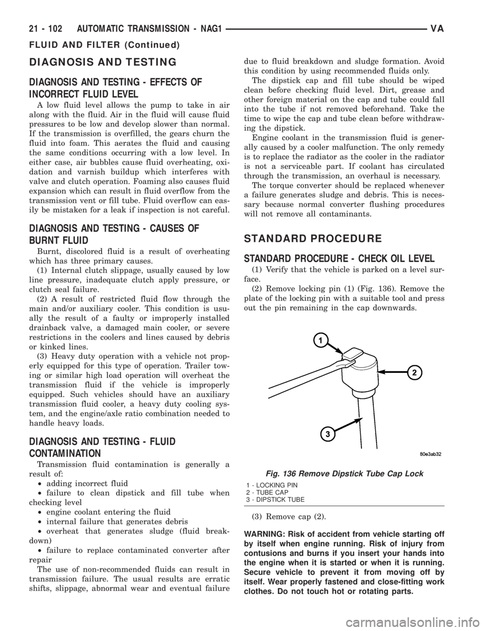
(2) Remove locking pin (1) (Fig. 136). Remove the
plate of the locking pin with a suitable tool and press
out the pin remaining in the cap downwards.
(3) Remove cap (2).
WARNING: Risk of accident from vehicle starting off
by itself when engine running. Risk of injury from
contusions and burns if you insert your hands into
the engine when it is started or when it is running.
Secure vehicle to prevent it from moving off by
itself. Wear properly fastened and close-fitting work
clothes. Do not touch hot or rotating parts.
Fig. 136 Remove Dipstick Tube Cap Lock
1 - LOCKING PIN
2 - TUBE CAP
3 - DIPSTICK TUBE
21 - 102 AUTOMATIC TRANSMISSION - NAG1VA
FLUID AND FILTER (Continued)
Page 996 of 1232
OIL PUMP
DESCRIPTION
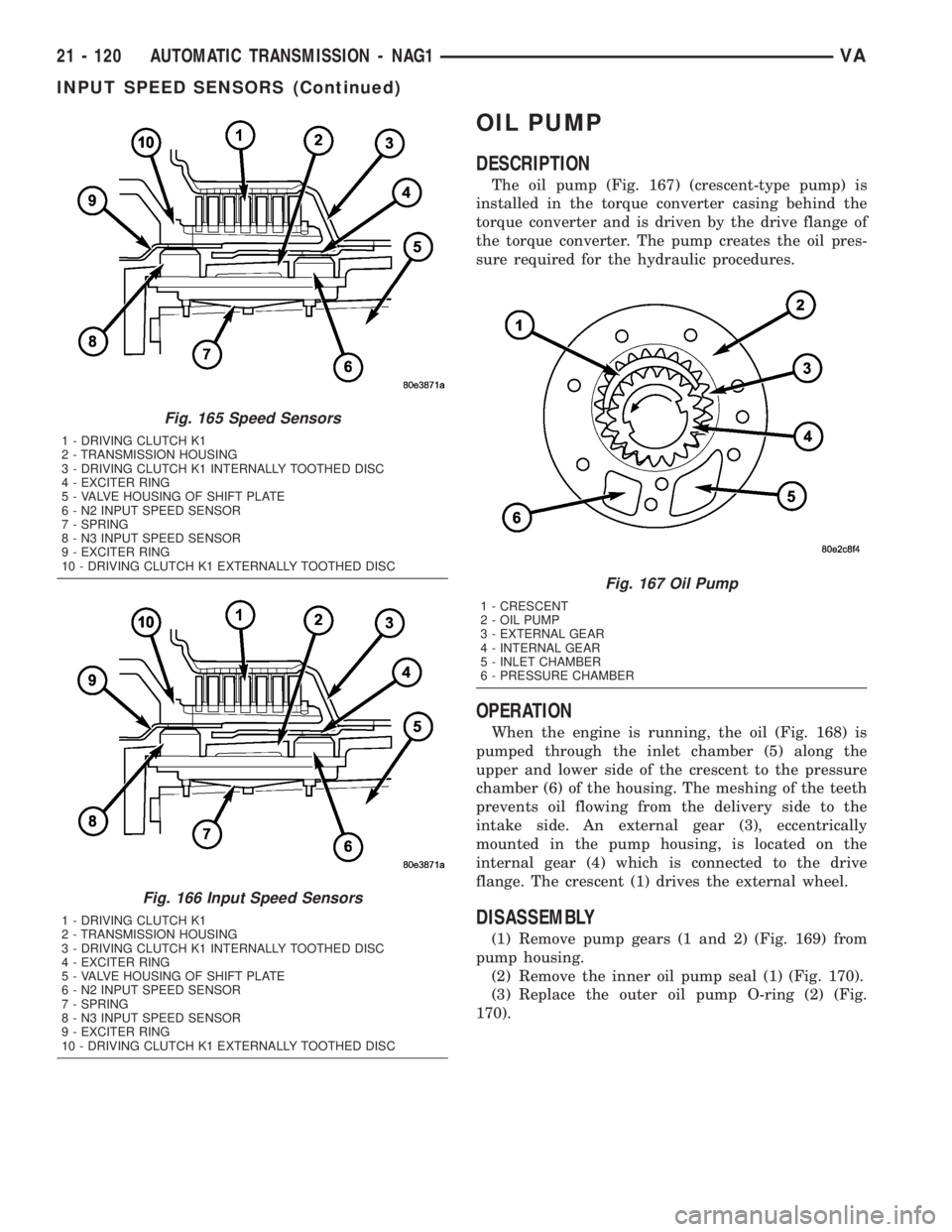
The oil pump (Fig. 167) (crescent-type pump) is
installed in the torque converter casing behind the
torque converter and is driven by the drive flange of
the torque converter. The pump creates the oil pres-
sure required for the hydraulic procedures.
OPERATION
When the engine is running, the oil (Fig. 168) is
pumped through the inlet chamber (5) along the
upper and lower side of the crescent to the pressure
chamber (6) of the housing. The meshing of the teeth
prevents oil flowing from the delivery side to the
intake side. An external gear (3), eccentrically
mounted in the pump housing, is located on the
internal gear (4) which is connected to the drive
flange. The crescent (1) drives the external wheel.
DISASSEMBLY
(1) Remove pump gears (1 and 2) (Fig. 169) from
pump housing.
(2) Remove the inner oil pump seal (1) (Fig. 170).
(3) Replace the outer oil pump O-ring (2) (Fig.
170).
Fig. 165 Speed Sensors
1 - DRIVING CLUTCH K1
2 - TRANSMISSION HOUSING
3 - DRIVING CLUTCH K1 INTERNALLY TOOTHED DISC
4 - EXCITER RING
5 - VALVE HOUSING OF SHIFT PLATE
6 - N2 INPUT SPEED SENSOR
7 - SPRING
8 - N3 INPUT SPEED SENSOR
9 - EXCITER RING
10 - DRIVING CLUTCH K1 EXTERNALLY TOOTHED DISC
Fig. 166 Input Speed Sensors
1 - DRIVING CLUTCH K1
2 - TRANSMISSION HOUSING
3 - DRIVING CLUTCH K1 INTERNALLY TOOTHED DISC
4 - EXCITER RING
5 - VALVE HOUSING OF SHIFT PLATE
6 - N2 INPUT SPEED SENSOR
7 - SPRING
8 - N3 INPUT SPEED SENSOR
9 - EXCITER RING
10 - DRIVING CLUTCH K1 EXTERNALLY TOOTHED DISC
Fig. 167 Oil Pump
1 - CRESCENT
2 - OIL PUMP
3 - EXTERNAL GEAR
4 - INTERNAL GEAR
5 - INLET CHAMBER
6 - PRESSURE CHAMBER
21 - 120 AUTOMATIC TRANSMISSION - NAG1VA
INPUT SPEED SENSORS (Continued)
Page 1042 of 1232
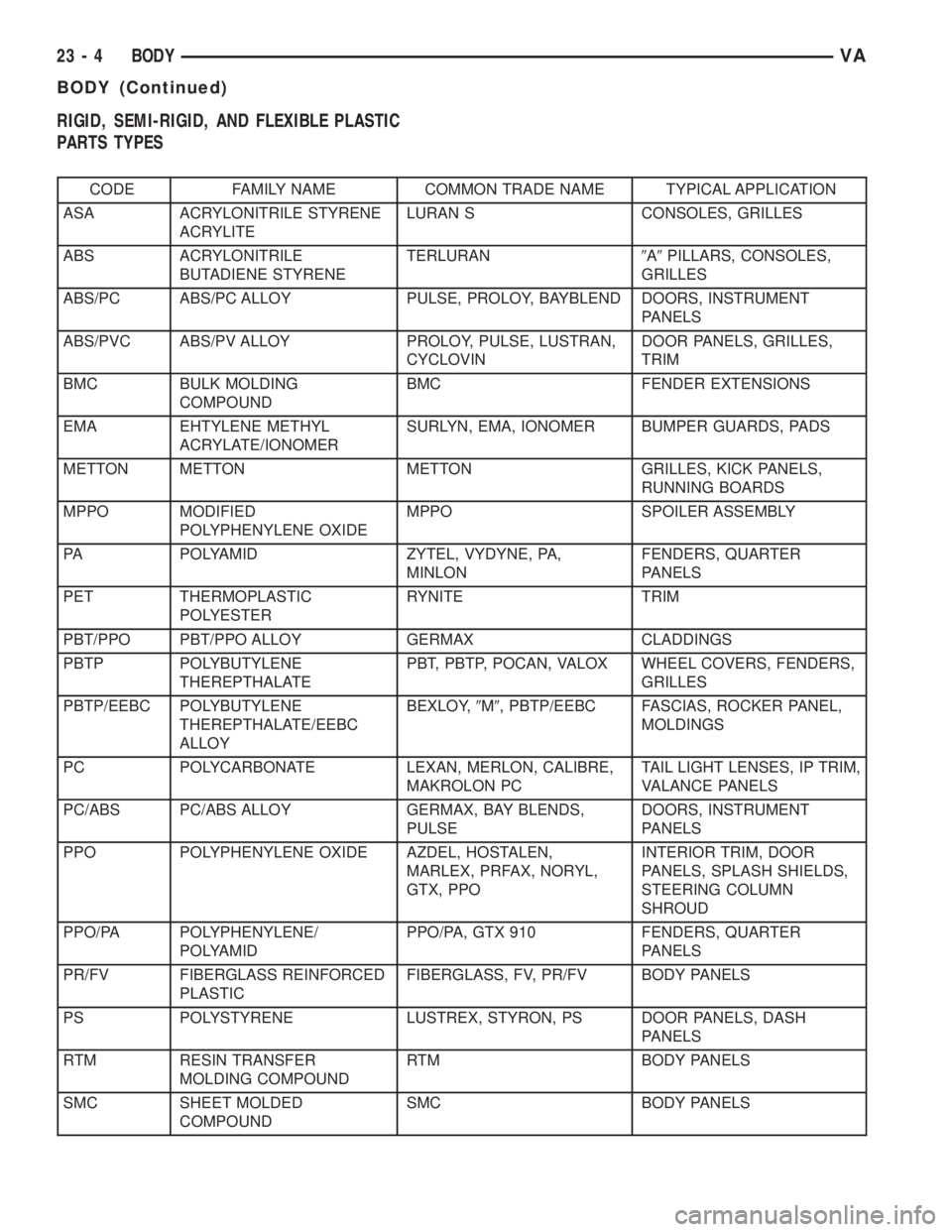
RIGID, SEMI-RIGID, AND FLEXIBLE PLASTIC
PARTS TYPES
CODE FAMILY NAME COMMON TRADE NAME TYPICAL APPLICATION
ASA ACRYLONITRILE STYRENE
ACRYLITELURAN S CONSOLES, GRILLES
ABS ACRYLONITRILE
BUTADIENE STYRENETERLURAN9A9PILLARS, CONSOLES,
GRILLES
ABS/PC ABS/PC ALLOY PULSE, PROLOY, BAYBLEND DOORS, INSTRUMENT
PANELS
ABS/PVC ABS/PV ALLOY PROLOY, PULSE, LUSTRAN,
CYCLOVINDOOR PANELS, GRILLES,
TRIM
BMC BULK MOLDING
COMPOUNDBMC FENDER EXTENSIONS
EMA EHTYLENE METHYL
ACRYLATE/IONOMERSURLYN, EMA, IONOMER BUMPER GUARDS, PADS
METTON METTON METTON GRILLES, KICK PANELS,
RUNNING BOARDS
MPPO MODIFIED
POLYPHENYLENE OXIDEMPPO SPOILER ASSEMBLY
PA POLYAMID ZYTEL, VYDYNE, PA,
MINLONFENDERS, QUARTER
PANELS
PET THERMOPLASTIC
POLYESTERRYNITE TRIM
PBT/PPO PBT/PPO ALLOY GERMAX CLADDINGS
PBTP POLYBUTYLENE
THEREPTHALATEPBT, PBTP, POCAN, VALOX WHEEL COVERS, FENDERS,
GRILLES
PBTP/EEBC POLYBUTYLENE
THEREPTHALATE/EEBC
ALLOYBEXLOY,9M9, PBTP/EEBC FASCIAS, ROCKER PANEL,
MOLDINGS
PC POLYCARBONATE LEXAN, MERLON, CALIBRE,
MAKROLON PCTAIL LIGHT LENSES, IP TRIM,
VALANCE PANELS
PC/ABS PC/ABS ALLOY GERMAX, BAY BLENDS,
PULSEDOORS, INSTRUMENT
PANELS
PPO POLYPHENYLENE OXIDE AZDEL, HOSTALEN,
MARLEX, PRFAX, NORYL,
GTX, PPOINTERIOR TRIM, DOOR
PANELS, SPLASH SHIELDS,
STEERING COLUMN
SHROUD
PPO/PA POLYPHENYLENE/
POLYAMIDPPO/PA, GTX 910 FENDERS, QUARTER
PANELS
PR/FV FIBERGLASS REINFORCED
PLASTICFIBERGLASS, FV, PR/FV BODY PANELS
PS POLYSTYRENE LUSTREX, STYRON, PS DOOR PANELS, DASH
PANELS
RTM RESIN TRANSFER
MOLDING COMPOUNDRTM BODY PANELS
SMC SHEET MOLDED
COMPOUNDSMC BODY PANELS
23 - 4 BODYVA
BODY (Continued)
Page 1045 of 1232
²The technician should first decide what needs to
be done when working on any type of body panel.
One should determine if it is possible to return the
damage part to its original strength and appearance
without exceeding the value of the replacement part.
²When plastic repairs are required, it is recom-
mended that the part be left on the vehicle when
every possible. That will save time, and the panel
will remain stationary during the repair. Misalign-
ment can cause stress in the repair areas and can
result in future failure.
VISUAL INSPECTION
Composite materials can mask the severity of an
accident. Adhesive bond lines, interior structure of
the doors, and steel structures need to be inspected
carefully to get a true damage assessment. Close
inspection may require partial removal of interior
trim or inner panels.
Identify the type of repair: Puncture or Crack -
Damage that has penetrated completely through the
panel. Damage is confined to one general area; a
panel section is not required. However, a backer
panel, open fiberglass tape, or matted material must
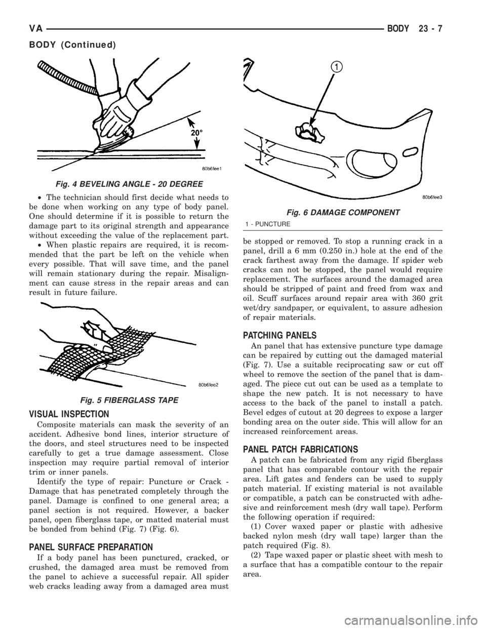
be bonded from behind (Fig. 7) (Fig. 6).
PANEL SURFACE PREPARATION
If a body panel has been punctured, cracked, or
crushed, the damaged area must be removed from
the panel to achieve a successful repair. All spider
web cracks leading away from a damaged area mustbe stopped or removed. To stop a running crack in a
panel, drilla6mm(0.250 in.) hole at the end of the
crack farthest away from the damage. If spider web
cracks can not be stopped, the panel would require
replacement. The surfaces around the damaged area
should be stripped of paint and freed from wax and
oil. Scuff surfaces around repair area with 360 grit
wet/dry sandpaper, or equivalent, to assure adhesion
of repair materials.
PATCHING PANELS
An panel that has extensive puncture type damage
can be repaired by cutting out the damaged material
(Fig. 7). Use a suitable reciprocating saw or cut off
wheel to remove the section of the panel that is dam-
aged. The piece cut out can be used as a template to
shape the new patch. It is not necessary to have
access to the back of the panel to install a patch.
Bevel edges of cutout at 20 degrees to expose a larger
bonding area on the outer side. This will allow for an
increased reinforcement areas.
PANEL PATCH FABRICATIONS
A patch can be fabricated from any rigid fiberglass
panel that has comparable contour with the repair
area. Lift gates and fenders can be used to supply
patch material. If existing material is not available
or compatible, a patch can be constructed with adhe-
sive and reinforcement mesh (dry wall tape). Perform
the following operation if required:
(1) Cover waxed paper or plastic with adhesive
backed nylon mesh (dry wall tape) larger than the
patch required (Fig. 8).
(2) Tape waxed paper or plastic sheet with mesh to
a surface that has a compatible contour to the repair
area.
Fig. 4 BEVELING ANGLE - 20 DEGREE
Fig. 5 FIBERGLASS TAPE
Fig. 6 DAMAGE COMPONENT
1 - PUNCTURE
VABODY 23 - 7
BODY (Continued)
Page 1137 of 1232
The compressor clutch engagement is controlled by
several components:
²A/C switch on the A/C-heater control panel
²Evaporator temperature sensor
²A/C pressure transducer
²Air temperature sensor
²CAN bus messages
The compressor clutch is de-energized under any of
the following conditions:
²Blocked compressor (thermal fuse in the pulley)
²Low pressure in the system
²Low evaporator temperature
²Hard acceleration (WOT)
²High coolant temperatures
STANDARD PROCEDURE
STANDARD PROCEDURE - COMPRESSOR
CLUTCH AIR GAP
If a new clutch plate and/or clutch pulley are being
used, the air gap between the clutch plate and clutch
pulley must be checked using the following proce-
dure:
(1) Using feeler gauges, measure the air gap
between the clutch plate and the clutch pulley fric-
tion surfaces.
(2) If the air gap is not between 0.5 and 0.9 mm
(0.020 and 0.035 in.), add or subtract shims until the
desired air gap is obtained.
NOTE: The shims may compress after tightening
the compressor shaft bolt. Check the air gap in four
or more places on the clutch plate to verify that theair gap is still correct. Spin the clutch pulley before
making the final air gap check.
STANDARD PROCEDURE - COMPRESSOR
CLUTCH BREAK-IN
After a new compressor clutch has been installed,
cycle the compressor clutch approximately twenty
times (five seconds on, then five seconds off). During
this procedure, set the heater-A/C control in the
Recirculation Mode, the A/C button in the on posi-
tion, the blower motor switch in the highest speed
position, and the engine speed at 1500 to 2000 rpm.
This procedure (burnishing) will seat the opposing
friction surfaces and provide a higher compressor
clutch torque capability.
REMOVAL
The refrigerant system can remain fully-charged
during compressor clutch, pulley, or coil replacement.
The compressor clutch can be serviced in the vehicle.
(1) Disconnect and isolate the battery negative
cable.
(2) Remove the serpentine drive belt (Refer to 7 -
COOLING/ACCESSORY DRIVE/DRIVE BELTS -
REMOVAL).
(3) Disconnect the engine wire harness connector
for the compressor clutch coil from the clutch coil
wire harness connector on the top of the compressor.
(4) Disengage the retainer on the engine wire har-
ness compressor clutch coil lead from the bracket on
the top of the compressor.
(5) Remove the bolt that secures the compressor
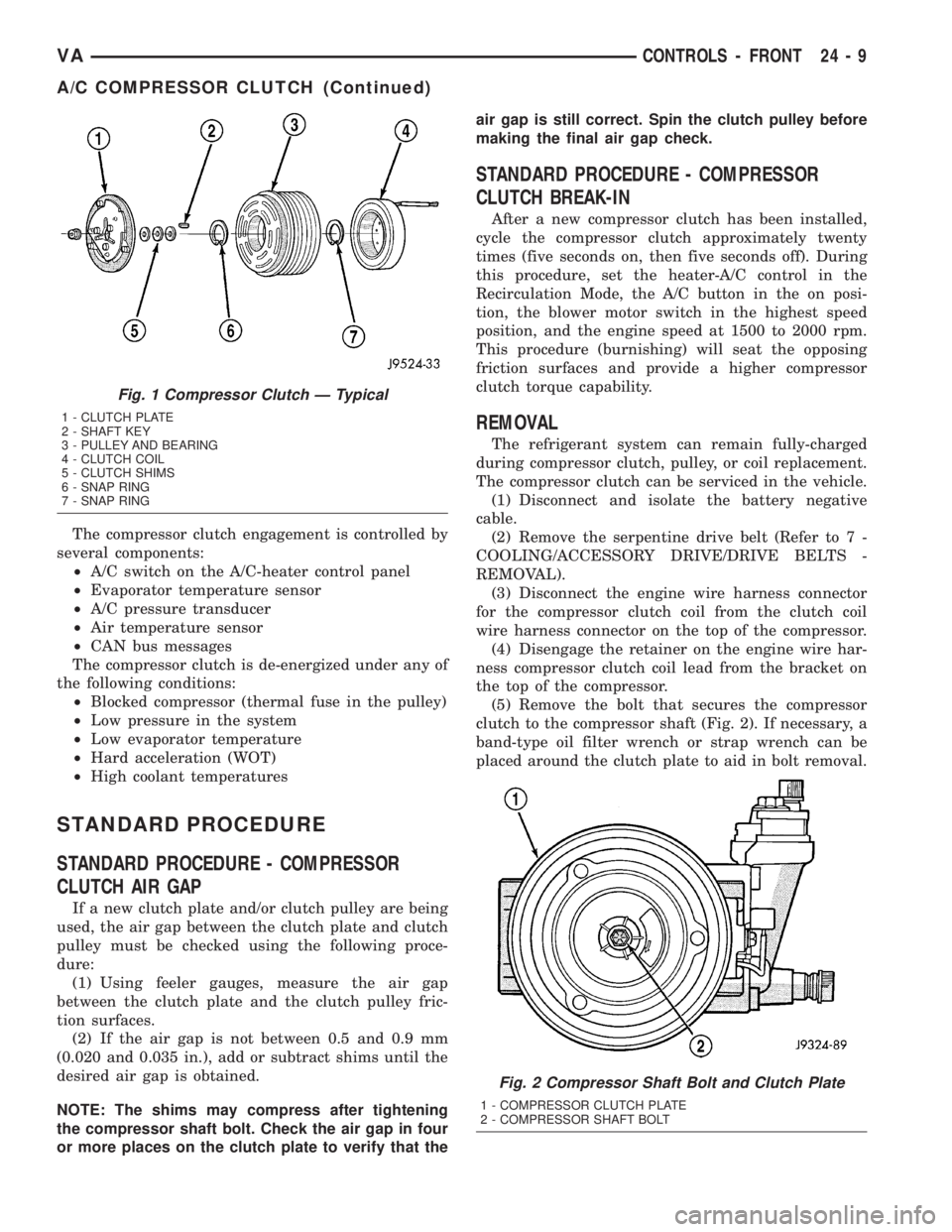
clutch to the compressor shaft (Fig. 2). If necessary, a
band-type oil filter wrench or strap wrench can be
placed around the clutch plate to aid in bolt removal.
Fig. 1 Compressor Clutch Ð Typical
1 - CLUTCH PLATE
2 - SHAFT KEY
3 - PULLEY AND BEARING
4 - CLUTCH COIL
5 - CLUTCH SHIMS
6 - SNAP RING
7 - SNAP RING
Fig. 2 Compressor Shaft Bolt and Clutch Plate
1 - COMPRESSOR CLUTCH PLATE
2 - COMPRESSOR SHAFT BOLT
VACONTROLS - FRONT 24 - 9
A/C COMPRESSOR CLUTCH (Continued)
Page 1139 of 1232
(2) Examine the friction surfaces of the clutch pul-
ley and the clutch plate for oil contamination. If the
friction surfaces are oily, the clutch pulley and clutch
plate should be replaced. Also inspect the shaft and
nose area of the compressor for oil. Remove the felt
packing from around the compressor shaft in the
compressor front cover. If the felt is saturated with
oil, the compressor front shaft seal is leaking and the
compressor will also have to be replaced.
(3) Check the clutch pulley bearing for roughness
or excessive leakage of grease. Replace the clutch
pulley and clutch plate if the bearing is faulty.
INSTALLATION
(1) Align the dowel pin on the back of the clutch
field coil with the hole in the compressor front cover,
and position the clutch coil onto the compressor. Be
certain that the cluch coil wire harness leads are
properly oriented and routed so that they are not
pinched between the compressor front cover and the
clutch coil.
NOTE: A new snap ring must be used to secure the
clutch coil to the compressor. The bevel side of the
snap ring must face outward.
(2) Using snap ring pliers (Special Tool C-4574 or
equivalent), install the external snap ring that
secures the clutch coil to the front cover of the com-
pressor. The bevel side of the snap ring must be fac-
ing outward and both snap ring eyelets must be
oriented to the right or left of the clutch coil dowel
pin on the compressor. Be certain that the snap ring
is fully and properly seated in the groove.
CAUTION: If the snap ring is not fully seated in the
groove it will vibrate out, resulting in a clutch fail-
ure and severe damage to the compressor front
cover.
(3) Install and tighten the screw that secures the
clutch coil wire harness connector bracket and
ground clip to the top of the compressor housing.
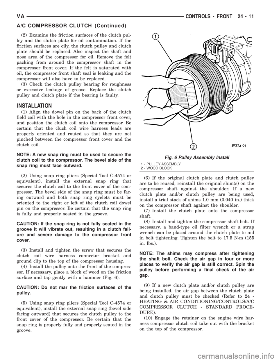
(4) Install the pulley onto the front of the compres-
sor. If necessary, place a block of wood on the friction
surface and tap gently with a hammer (Fig. 6).
CAUTION: Do not mar the friction surfaces of the
pulley.
(5) Using snap ring pliers (Special Tool C-4574 or
equivalent), install the external snap ring (bevel side
facing outward) that secures the clutch pulley to the
front cover of the compressor. Be certain that the
snap ring is properly fully and properly seated in the
groove.(6) If the original clutch plate and clutch pulley
are to be reused, reinstall the original shim(s) on the
compressor shaft against the shoulder. If a new
clutch plate and/or clutch pulley are being used,
install a trial stack of shims 1.0 mm (0.040 in.) thick
on the compressor shaft against the shoulder.
(7) Install the clutch plate onto the compressor
shaft.
(8) Install and tighten the compressor shaft bolt. If
necessary, a band-type oil filter wrench or a strap
wrench can be placed around the clutch plate to aid
in bolt tightening. Tighten the bolt to 17.5 N´m (155
in. lbs.).
NOTE: The shims may compress after tightening
the shaft bolt. Check the air gap in four or more
places to verify the air gap is still correct. Spin the
pulley before performing a final check of the air
gap.
(9) If a new clutch plate and/or clutch pulley are
being installed, the air gap between the clutch plate
and clutch pulley must be checked (Refer to 24 -
HEATING & AIR CONDITIONING/CONTROLS/A/C
COMPRESSOR CLUTCH - STANDARD PROCE-
DURE).
(10) Engage the retainer on the engine wire har-
ness compressor clutch coil take out with the bracket
on the top of the compressor.
Fig. 6 Pulley Assembly Install
1 - PULLEY ASSEMBLY
2 - WOOD BLOCK
VACONTROLS - FRONT 24 - 11
A/C COMPRESSOR CLUTCH (Continued)