2005 MERCEDES-BENZ SPRINTER Fluid
[x] Cancel search: FluidPage 76 of 1232
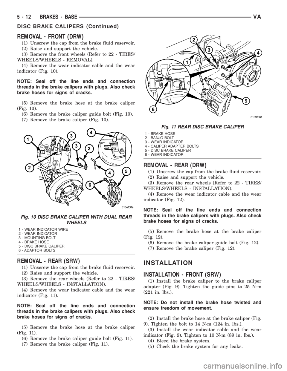
REMOVAL - FRONT (DRW)
(1) Unscrew the cap from the brake fluid reservoir.
(2) Raise and support the vehicle.
(3) Remove the front wheels (Refer to 22 - TIRES/
WHEELS/WHEELS - REMOVAL).
(4) Remove the wear indicator cable and the wear
indicator (Fig. 10).
NOTE: Seal off the line ends and connection
threads in the brake calipers with plugs. Also check
brake hoses for signs of cracks.
(5) Remove the brake hose at the brake caliper
(Fig. 10).
(6) Remove the brake caliper guide bolt (Fig. 10).
(7) Remove the brake caliper (Fig. 10).
REMOVAL - REAR (SRW)
(1) Unscrew the cap from the brake fluid reservoir.
(2) Raise and support the vehicle.
(3) Remove the rear wheels (Refer to 22 - TIRES/
WHEELS/WHEELS - INSTALLATION).
(4) Remove the wear indicator cable and the wear
indicator (Fig. 11).
NOTE: Seal off the line ends and connection
threads in the brake calipers with plugs. Also check
brake hoses for signs of cracks.
(5) Remove the brake hose at the brake caliper
(Fig. 11).
(6) Remove the brake caliper guide bolt (Fig. 11).
(7) Remove the brake caliper (Fig. 11).
REMOVAL - REAR (DRW)
(1) Unscrew the cap from the brake fluid reservoir.
(2) Raise and support the vehicle.
(3) Remove the rear wheels (Refer to 22 - TIRES/
WHEELS/WHEELS - INSTALLATION).
(4) Remove the wear indicator cable and the wear
indicator (Fig. 12).
NOTE: Seal off the line ends and connection
threads in the brake calipers with plugs. Also check
brake hoses for signs of cracks.
(5) Remove the brake hose at the brake caliper
(Fig. 12).
(6) Remove the brake caliper guide bolt (Fig. 12).
(7) Remove the brake caliper (Fig. 12).
INSTALLATION
INSTALLATION - FRONT (SRW)
(1) Install the brake caliper to the brake caliper
adapter (Fig. 9). Tighten the guide pins to 25 N´m
(221 in. lbs.).
NOTE: Do not install the brake hose twisted and
ensure freedom of movement.
(2) Install the brake hose at the brake caliper (Fig.
9). Tighten the bolt to 14 N´m (124 in. lbs.).
(3) Install the wear indicator cable and the wear
indicator (Fig. 9). Tighten to 10 N´m (89 in. lbs.).
(4) Bleed the brake system.
(5) Check the brake system for any leaks.
Fig. 10 DISC BRAKE CALIPER WITH DUAL REAR
WHEELS
1 - WEAR INDICATOR WIRE
2 - WEAR INDICATOR
3 - MOUNTING BOLT
4 - BRAKE HOSE
5 - DISC BRAKE CALIPER
6 - ADAPTOR BOLTS
Fig. 11 REAR DISC BRAKE CALIPER
1 - BRAKE HOSE
2 - BANJO BOLT
3 - WEAR INDICATOR
4 - CALIPER ADAPTER BOLTS
5 - DISC BRAKE CALIPER
6 - WEAR INDICATOR
5 - 12 BRAKES - BASEVA
DISC BRAKE CALIPERS (Continued)
Page 77 of 1232
(6) Install the front wheels.
(7) Lower the vehicle.
INSTALLATION - FRONT (DRW)
(1) Install the brake caliper to the brake caliper
adapter (Fig. 10). Tighten the guide pins to 25 N´m
(221 in. lbs.)(M8 bolt) or Tighten the guide pins to 30
N´m (265 in. lbs.)(M10 10.9 bolt).
NOTE: Do not install the brake hose twisted and
ensure freedom of movement.
(2) Install the brake hose at the brake caliper (Fig.
10). Tighten the bolt to 14 N´m (124 in. lbs.).
(3) Install the wear indicator cable and the wear
indicator (Fig. 10). Tighten to 10 N´m (89 in. lbs.).
(4) Bleed the brake system.
(5) Check the brake system for any leaks.
(6) Install the front wheels.
(7) Lower the vehicle.
INSTALLATION - REAR (SRW)
(1) Install the brake caliper to brake caliper
adapter (Fig. 11). Tighten the guide bolt to 25 N´m
(221 in. lbs.) for M8 bolt or 30 N´m (266 in. lbs.) for
M10 bolt.
NOTE: Do not install the brake hose twisted and
ensure freedom of movement.
(2) Install the brake hose at the brake caliper (Fig.
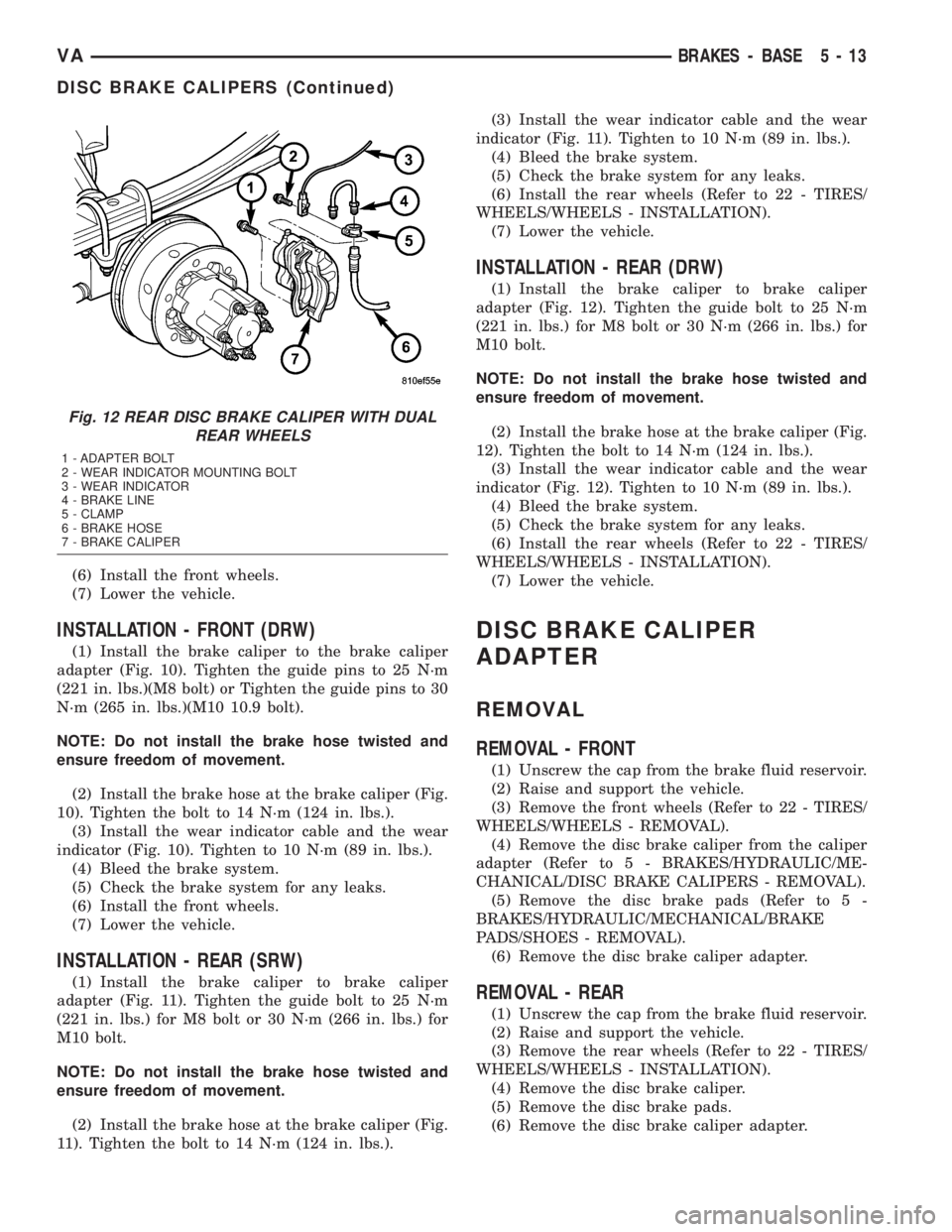
11). Tighten the bolt to 14 N´m (124 in. lbs.).(3) Install the wear indicator cable and the wear
indicator (Fig. 11). Tighten to 10 N´m (89 in. lbs.).
(4) Bleed the brake system.
(5) Check the brake system for any leaks.
(6) Install the rear wheels (Refer to 22 - TIRES/
WHEELS/WHEELS - INSTALLATION).
(7) Lower the vehicle.
INSTALLATION - REAR (DRW)
(1) Install the brake caliper to brake caliper
adapter (Fig. 12). Tighten the guide bolt to 25 N´m
(221 in. lbs.) for M8 bolt or 30 N´m (266 in. lbs.) for
M10 bolt.
NOTE: Do not install the brake hose twisted and
ensure freedom of movement.
(2) Install the brake hose at the brake caliper (Fig.
12). Tighten the bolt to 14 N´m (124 in. lbs.).
(3) Install the wear indicator cable and the wear
indicator (Fig. 12). Tighten to 10 N´m (89 in. lbs.).
(4) Bleed the brake system.
(5) Check the brake system for any leaks.
(6) Install the rear wheels (Refer to 22 - TIRES/
WHEELS/WHEELS - INSTALLATION).
(7) Lower the vehicle.
DISC BRAKE CALIPER
ADAPTER
REMOVAL
REMOVAL - FRONT
(1) Unscrew the cap from the brake fluid reservoir.
(2) Raise and support the vehicle.
(3) Remove the front wheels (Refer to 22 - TIRES/
WHEELS/WHEELS - REMOVAL).
(4) Remove the disc brake caliper from the caliper
adapter (Refer to 5 - BRAKES/HYDRAULIC/ME-
CHANICAL/DISC BRAKE CALIPERS - REMOVAL).
(5) Remove the disc brake pads (Refer to 5 -
BRAKES/HYDRAULIC/MECHANICAL/BRAKE
PADS/SHOES - REMOVAL).
(6) Remove the disc brake caliper adapter.
REMOVAL - REAR
(1) Unscrew the cap from the brake fluid reservoir.
(2) Raise and support the vehicle.
(3) Remove the rear wheels (Refer to 22 - TIRES/
WHEELS/WHEELS - INSTALLATION).
(4) Remove the disc brake caliper.
(5) Remove the disc brake pads.
(6) Remove the disc brake caliper adapter.
Fig. 12 REAR DISC BRAKE CALIPER WITH DUAL
REAR WHEELS
1 - ADAPTER BOLT
2 - WEAR INDICATOR MOUNTING BOLT
3 - WEAR INDICATOR
4 - BRAKE LINE
5 - CLAMP
6 - BRAKE HOSE
7 - BRAKE CALIPER
VABRAKES - BASE 5 - 13
DISC BRAKE CALIPERS (Continued)
Page 78 of 1232
INSTALLATION
INSTALLATION - FRONT
(1) Install the brake caliper adapter to the steering
knuckle. Tighten to 170 N´m (125 ft. lbs.).
(2) Install the disc brake shoes (Refer to 5 -
BRAKES/HYDRAULIC/MECHANICAL/BRAKE
PADS/SHOES - INSTALLATION).
NOTE: Do not install the brake hose twisted and
ensure freedom of movement.
(3) Install the disc brake caliper. Tighten the bolt
to 14 N´m (124 in. lbs.) (Refer to 5 - BRAKES/HY-
DRAULIC/MECHANICAL/DISC BRAKE CALIPERS
- INSTALLATION).
(4) Install the front wheels (Refer to 22 - TIRES/
WHEELS/WHEELS - INSTALLATION).
(5) Lower the vehicle.
INSTALLATION - REAR
(1) Install the brake caliper adapter to the axle
mount. Tighten to 90 N´m (66 ft. lbs.) for M12X1.5
bolt or 170 N´m (125 ft. lbs.) for M14X1.5 bolt.
(2) Install the disc brake pads (Refer to 5 -
BRAKES/HYDRAULIC/MECHANICAL/BRAKE
PADS/SHOES - INSTALLATION).
NOTE: Do not install the brake hose twisted and
ensure freedom of movement.
(3) Install the disc brake caliper (Refer to 5 -
BRAKES/HYDRAULIC/MECHANICAL/DISC
BRAKE CALIPERS - INSTALLATION).
(4) Install the rear wheels (Refer to 22 - TIRES/
WHEELS/WHEELS - INSTALLATION).
(5) Lower the vehicle.
FLUID
DIAGNOSIS AND TESTING - BRAKE FLUID
CONTAMINATION
Indications of fluid contamination are swollen or
deteriorated rubber parts.
Swollen rubber parts indicate the presence of
petroleum in the brake fluid.
To test for contamination, put a small amount of
drained brake fluid in clear glass jar. If fluid sepa-
rates into layers, there is mineral oil or other fluid
contamination of the brake fluid.
If brake fluid is contaminated, drain and thor-
oughly flush system. Replace master cylinder, ALB
Controller, caliper seals, Antilock Brakes hydraulic
unit and all hydraulic fluid hoses.
STANDARD PROCEDURE - BRAKE FLUID
LEVEL
Always clean the master cylinder reservoir and
caps before checking fluid level. If not cleaned, dirt
could enter the fluid.
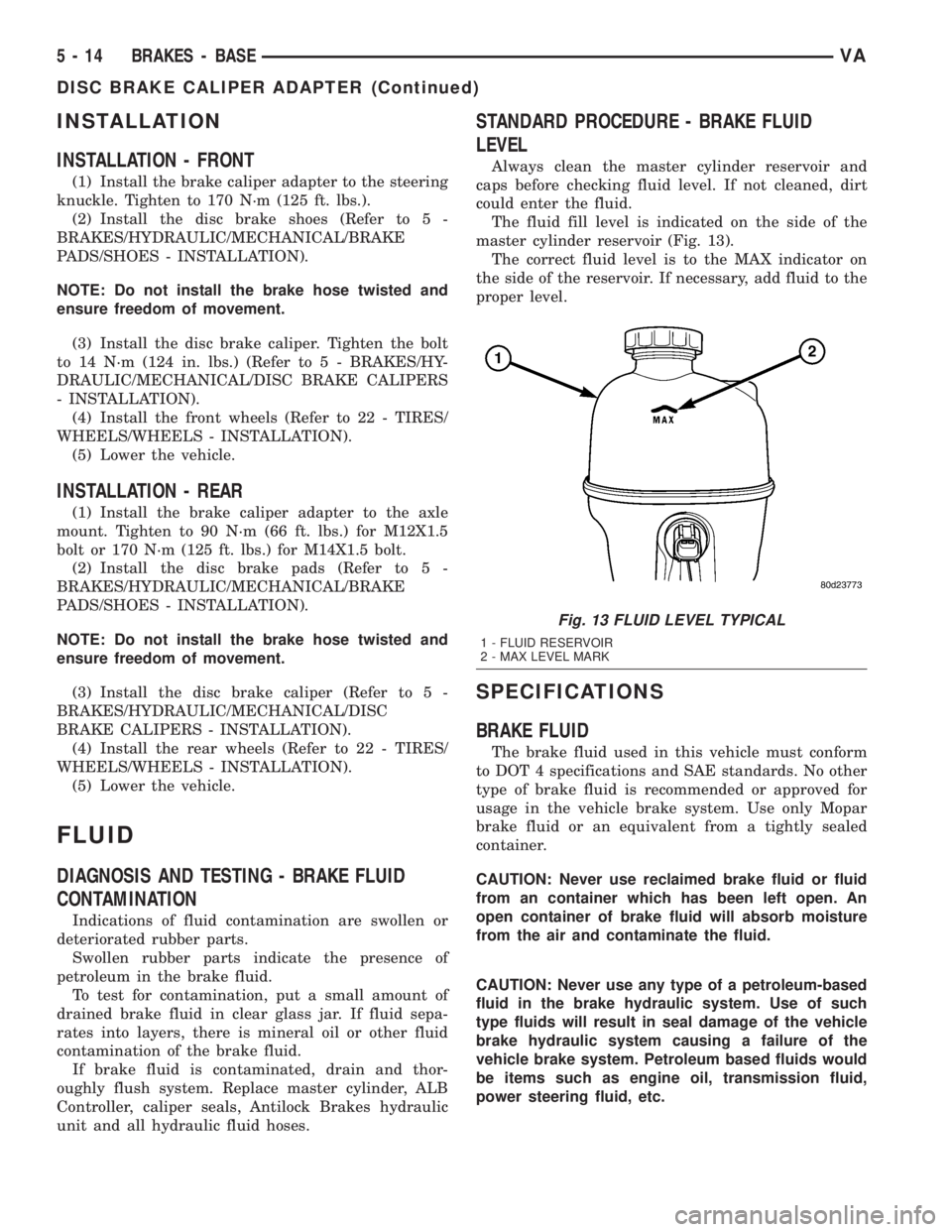
The fluid fill level is indicated on the side of the
master cylinder reservoir (Fig. 13).
The correct fluid level is to the MAX indicator on
the side of the reservoir. If necessary, add fluid to the
proper level.
SPECIFICATIONS
BRAKE FLUID
The brake fluid used in this vehicle must conform
to DOT 4 specifications and SAE standards. No other
type of brake fluid is recommended or approved for
usage in the vehicle brake system. Use only Mopar
brake fluid or an equivalent from a tightly sealed
container.
CAUTION: Never use reclaimed brake fluid or fluid
from an container which has been left open. An
open container of brake fluid will absorb moisture
from the air and contaminate the fluid.
CAUTION: Never use any type of a petroleum-based
fluid in the brake hydraulic system. Use of such
type fluids will result in seal damage of the vehicle
brake hydraulic system causing a failure of the
vehicle brake system. Petroleum based fluids would
be items such as engine oil, transmission fluid,
power steering fluid, etc.
Fig. 13 FLUID LEVEL TYPICAL
1 - FLUID RESERVOIR
2 - MAX LEVEL MARK
5 - 14 BRAKES - BASEVA
DISC BRAKE CALIPER ADAPTER (Continued)
Page 79 of 1232
FLUID RESERVOIR
REMOVAL
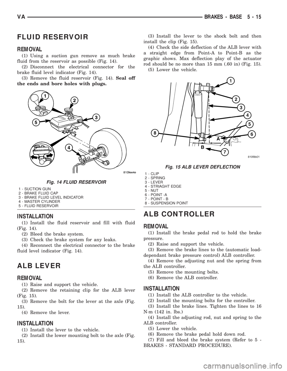
(1) Using a suction gun remove as much brake
fluid from the reservoir as possible (Fig. 14).
(2) Disconnect the electrical connector for the
brake fluid level indicator (Fig. 14).
(3) Remove the fluid reservoir (Fig. 14).Seal off
the ends and bore holes with plugs.
INSTALLATION
(1) Install the fluid reservoir and fill with fluid
(Fig. 14).
(2) Bleed the brake system.
(3) Check the brake system for any leaks.
(4) Reconnect the electrical connector to the brake
fluid level indicator (Fig. 14).
ALB LEVER
REMOVAL
(1) Raise and support the vehicle.
(2) Remove the retaining clip for the ALB lever
(Fig. 15).
(3) Remove the bolt for the lever at the axle (Fig.
15).
(4) Remove the lever.
INSTALLATION
(1) Install the lever to the vehicle.
(2) Install the lower mounting bolt to the axle (Fig.
15).(3) Install the lever to the shock bolt and then
install the clip (Fig. 15).
(4) Check the side deflection of the ALB lever with
a straight edge from Point-A to Point-B as the
graphic shows. Max deflection play of the actuator
rod should be no more than 15 mm (.60 in) (Fig. 15).
(5) Lower the vehicle.
ALB CONTROLLER
REMOVAL
(1) Install the brake pedal rod to hold the brake
pressure.
(2) Raise and support the vehicle.
(3) Remove the brake lines to the (automatic load-
dependant brake pressure control) ALB controller.
(4) Remove the adjusting nut and the spring from
the ALB controller.
(5) Remove the mounting bolts.
(6) Remove the ALB controller.
INSTALLATION
(1) Install the ALB controller to the vehicle.
(2) Install the mounting bolts for the controller.
(3) Install the brake lines. Tighten the lines to 16
N´m (142 in. lbs.)
(4) Install the adjusting rod, nut and spring to the
ALB controller.
(5) Lower the vehicle.
(6) Remove the brake pedal hold down rod.
(7) Fill and bleed the brake system (Refer to 5 -
BRAKES - STANDARD PROCEDURE).
Fig. 14 FLUID RESERVOIR
1 - SUCTION GUN
2 - BRAKE FLUID CAP
3 - BRAKE FLUID LEVEL INDICATOR
4 - MASTER CYLINDER
5 - FLUID RESERVOIR
Fig. 15 ALB LEVER DEFLECTION
1 - CLIP
2 - SPRING
3 - LEVER
4 - STRIAGHT EDGE
5 - NUT
6 - POINT -A
7 - POINT - B
8 - SUSPENSION POINT
VABRAKES - BASE 5 - 15
Page 81 of 1232
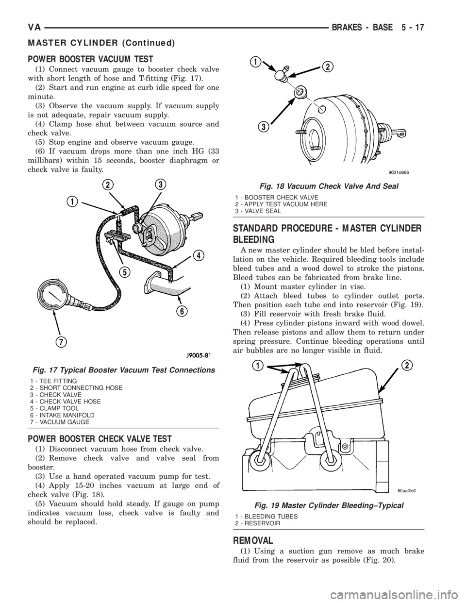
POWER BOOSTER VACUUM TEST
(1) Connect vacuum gauge to booster check valve
with short length of hose and T-fitting (Fig. 17).
(2) Start and run engine at curb idle speed for one
minute.
(3) Observe the vacuum supply. If vacuum supply
is not adequate, repair vacuum supply.
(4) Clamp hose shut between vacuum source and
check valve.
(5) Stop engine and observe vacuum gauge.
(6) If vacuum drops more than one inch HG (33
millibars) within 15 seconds, booster diaphragm or
check valve is faulty.
POWER BOOSTER CHECK VALVE TEST
(1) Disconnect vacuum hose from check valve.
(2) Remove check valve and valve seal from
booster.
(3) Use a hand operated vacuum pump for test.
(4) Apply 15-20 inches vacuum at large end of
check valve (Fig. 18).
(5) Vacuum should hold steady. If gauge on pump
indicates vacuum loss, check valve is faulty and
should be replaced.
STANDARD PROCEDURE - MASTER CYLINDER
BLEEDING
A new master cylinder should be bled before instal-
lation on the vehicle. Required bleeding tools include
bleed tubes and a wood dowel to stroke the pistons.
Bleed tubes can be fabricated from brake line.
(1) Mount master cylinder in vise.
(2) Attach bleed tubes to cylinder outlet ports.
Then position each tube end into reservoir (Fig. 19).
(3) Fill reservoir with fresh brake fluid.
(4) Press cylinder pistons inward with wood dowel.
Then release pistons and allow them to return under
spring pressure. Continue bleeding operations until
air bubbles are no longer visible in fluid.
REMOVAL
(1) Using a suction gun remove as much brake
fluid from the reservoir as possible (Fig. 20).
Fig. 17 Typical Booster Vacuum Test Connections
1 - TEE FITTING
2 - SHORT CONNECTING HOSE
3 - CHECK VALVE
4 - CHECK VALVE HOSE
5 - CLAMP TOOL
6 - INTAKE MANIFOLD
7 - VACUUM GAUGE
Fig. 18 Vacuum Check Valve And Seal
1 - BOOSTER CHECK VALVE
2 - APPLY TEST VACUUM HERE
3 - VALVE SEAL
Fig. 19 Master Cylinder Bleeding±Typical
1 - BLEEDING TUBES
2 - RESERVOIR
VABRAKES - BASE 5 - 17
MASTER CYLINDER (Continued)
Page 82 of 1232
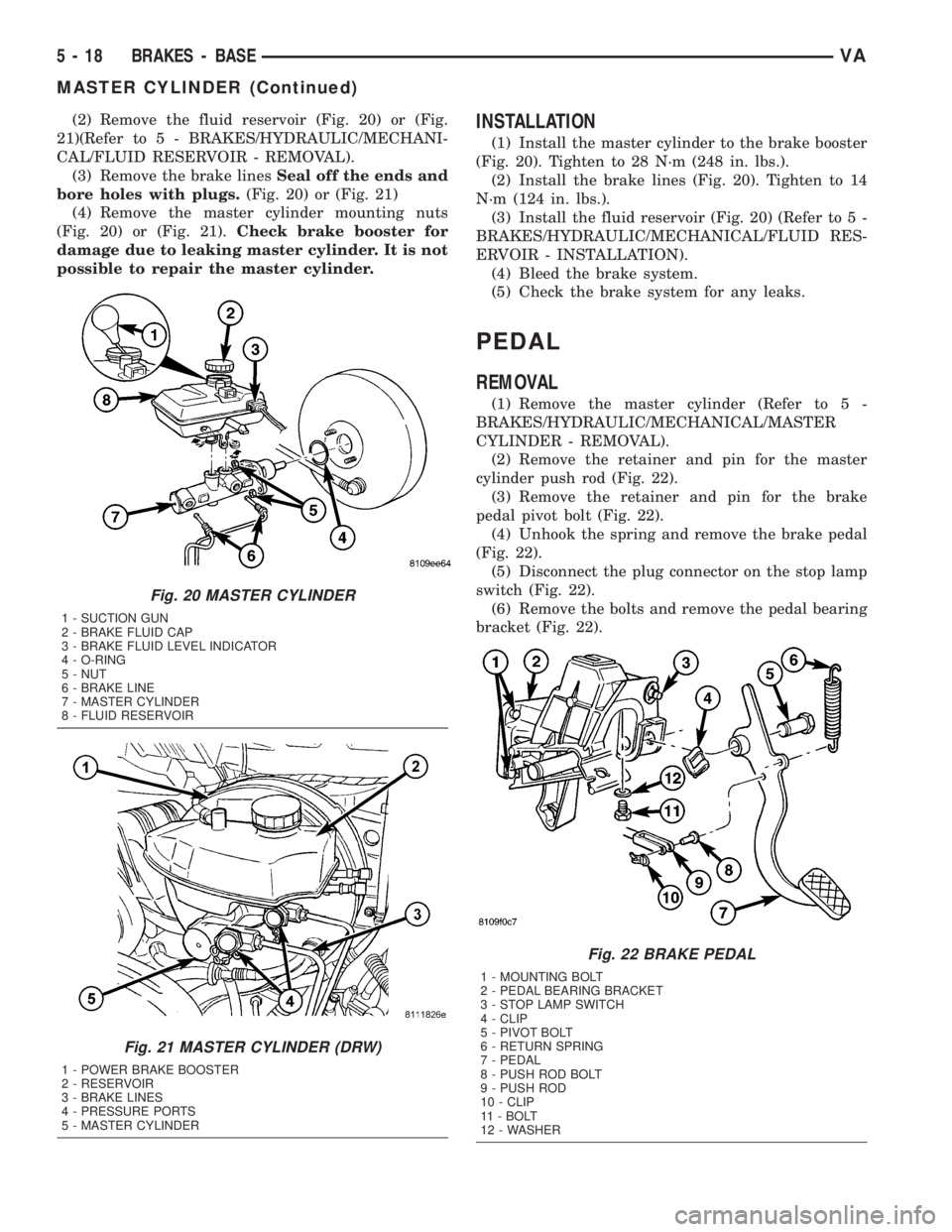
(2) Remove the fluid reservoir (Fig. 20) or (Fig.
21)(Refer to 5 - BRAKES/HYDRAULIC/MECHANI-
CAL/FLUID RESERVOIR - REMOVAL).
(3) Remove the brake linesSeal off the ends and
bore holes with plugs.(Fig. 20) or (Fig. 21)
(4) Remove the master cylinder mounting nuts
(Fig. 20) or (Fig. 21).Check brake booster for
damage due to leaking master cylinder. It is not
possible to repair the master cylinder.INSTALLATION
(1) Install the master cylinder to the brake booster
(Fig. 20). Tighten to 28 N´m (248 in. lbs.).
(2) Install the brake lines (Fig. 20). Tighten to 14
N´m (124 in. lbs.).
(3) Install the fluid reservoir (Fig. 20) (Refer to 5 -
BRAKES/HYDRAULIC/MECHANICAL/FLUID RES-
ERVOIR - INSTALLATION).
(4) Bleed the brake system.
(5) Check the brake system for any leaks.
PEDAL
REMOVAL
(1) Remove the master cylinder (Refer to 5 -
BRAKES/HYDRAULIC/MECHANICAL/MASTER
CYLINDER - REMOVAL).
(2) Remove the retainer and pin for the master
cylinder push rod (Fig. 22).
(3) Remove the retainer and pin for the brake
pedal pivot bolt (Fig. 22).
(4) Unhook the spring and remove the brake pedal
(Fig. 22).
(5) Disconnect the plug connector on the stop lamp
switch (Fig. 22).
(6) Remove the bolts and remove the pedal bearing
bracket (Fig. 22).
Fig. 20 MASTER CYLINDER
1 - SUCTION GUN
2 - BRAKE FLUID CAP
3 - BRAKE FLUID LEVEL INDICATOR
4 - O-RING
5 - NUT
6 - BRAKE LINE
7 - MASTER CYLINDER
8 - FLUID RESERVOIR
Fig. 21 MASTER CYLINDER (DRW)
1 - POWER BRAKE BOOSTER
2 - RESERVOIR
3 - BRAKE LINES
4 - PRESSURE PORTS
5 - MASTER CYLINDER
Fig. 22 BRAKE PEDAL
1 - MOUNTING BOLT
2 - PEDAL BEARING BRACKET
3 - STOP LAMP SWITCH
4 - CLIP
5 - PIVOT BOLT
6 - RETURN SPRING
7 - PEDAL
8 - PUSH ROD BOLT
9 - PUSH ROD
10 - CLIP
11 - BOLT
12 - WASHER
5 - 18 BRAKES - BASEVA
MASTER CYLINDER (Continued)
Page 83 of 1232
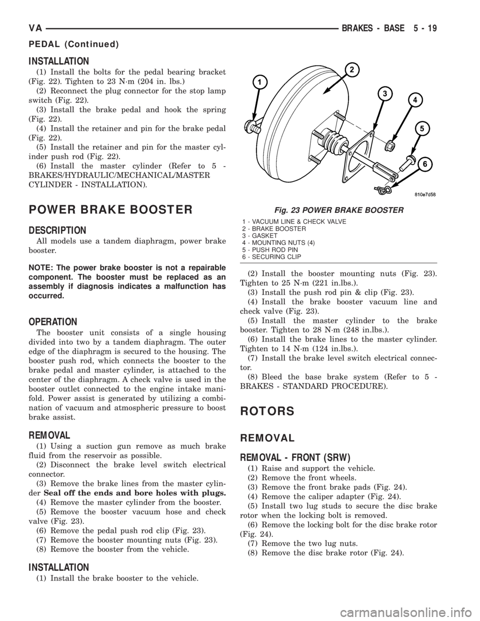
INSTALLATION
(1) Install the bolts for the pedal bearing bracket
(Fig. 22). Tighten to 23 N´m (204 in. lbs.)
(2) Reconnect the plug connector for the stop lamp
switch (Fig. 22).
(3) Install the brake pedal and hook the spring
(Fig. 22).
(4) Install the retainer and pin for the brake pedal
(Fig. 22).
(5) Install the retainer and pin for the master cyl-
inder push rod (Fig. 22).
(6) Install the master cylinder (Refer to 5 -
BRAKES/HYDRAULIC/MECHANICAL/MASTER
CYLINDER - INSTALLATION).
POWER BRAKE BOOSTER
DESCRIPTION
All models use a tandem diaphragm, power brake
booster.
NOTE: The power brake booster is not a repairable
component. The booster must be replaced as an
assembly if diagnosis indicates a malfunction has
occurred.
OPERATION
The booster unit consists of a single housing
divided into two by a tandem diaphragm. The outer
edge of the diaphragm is secured to the housing. The
booster push rod, which connects the booster to the
brake pedal and master cylinder, is attached to the
center of the diaphragm. A check valve is used in the
booster outlet connected to the engine intake mani-
fold. Power assist is generated by utilizing a combi-
nation of vacuum and atmospheric pressure to boost
brake assist.
REMOVAL
(1) Using a suction gun remove as much brake
fluid from the reservoir as possible.
(2) Disconnect the brake level switch electrical
connector.
(3) Remove the brake lines from the master cylin-
derSeal off the ends and bore holes with plugs.
(4) Remove the master cylinder from the booster.
(5) Remove the booster vacuum hose and check
valve (Fig. 23).
(6) Remove the pedal push rod clip (Fig. 23).
(7) Remove the booster mounting nuts (Fig. 23).
(8) Remove the booster from the vehicle.
INSTALLATION
(1) Install the brake booster to the vehicle.(2) Install the booster mounting nuts (Fig. 23).
Tighten to 25 N´m (221 in.lbs.).
(3) Install the push rod pin & clip (Fig. 23).
(4) Install the brake booster vacuum line and
check valve (Fig. 23).
(5) Install the master cylinder to the brake
booster. Tighten to 28 N´m (248 in.lbs.).
(6) Install the brake lines to the master cylinder.
Tighten to 14 N´m (124 in.lbs.).
(7) Install the brake level switch electrical connec-
tor.
(8) Bleed the base brake system (Refer to 5 -
BRAKES - STANDARD PROCEDURE).
ROTORS
REMOVAL
REMOVAL - FRONT (SRW)
(1) Raise and support the vehicle.
(2) Remove the front wheels.
(3) Remove the front brake pads (Fig. 24).
(4) Remove the caliper adapter (Fig. 24).
(5) Install two lug studs to secure the disc brake
rotor when the locking bolt is removed.
(6) Remove the locking bolt for the disc brake rotor
(Fig. 24).
(7) Remove the two lug nuts.
(8) Remove the disc brake rotor (Fig. 24).
Fig. 23 POWER BRAKE BOOSTER
1 - VACUUM LINE & CHECK VALVE
2 - BRAKE BOOSTER
3 - GASKET
4 - MOUNTING NUTS (4)
5 - PUSH ROD PIN
6 - SECURING CLIP
VABRAKES - BASE 5 - 19
PEDAL (Continued)
Page 85 of 1232
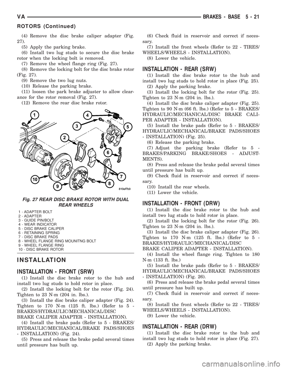
(4) Remove the disc brake caliper adapter (Fig.
27).
(5) Apply the parking brake.
(6) Install two lug studs to secure the disc brake
rotor when the locking bolt is removed.
(7) Remove the wheel flange ring (Fig. 27).
(8) Remove the locking bolt for the disc brake rotor
(Fig. 27).
(9) Remove the two lug nuts.
(10) Release the parking brake.
(11) loosen the park brake adjuster to allow clear-
ance for the rotor removal (Fig. 27).
(12) Remove the rear disc brake rotor.
INSTALLATION
INSTALLATION - FRONT (SRW)
(1) Install the disc brake rotor to the hub and
install two lug studs to hold rotor in place.
(2) Install the locking bolt for the rotor (Fig. 24).
Tighten to 23 N´m (204 in. lbs.).
(3) Install the disc brake caliper adapter (Fig. 24).
Tighten to 170 N´m (125 ft. lbs.) (Refer to 5 -
BRAKES/HYDRAULIC/MECHANICAL/DISC
BRAKE CALIPER ADAPTER - INSTALLATION).
(4) Install the brake pads (Refer to 5 - BRAKES/
HYDRAULIC/MECHANICAL/BRAKE PADS/SHOES
- INSTALLATION) (Fig. 24).
(5) Press and release the brake pedal several times
until pressure has built up.(6) Check fluid in reservoir and correct if neces-
sary.
(7) Install the front wheels (Refer to 22 - TIRES/
WHEELS/WHEELS - INSTALLATION).
(8) Lower the vehicle.
INSTALLATION - REAR (SRW)
(1) Install the disc brake rotor to the hub and
install two lug studs to hold rotor in place (Fig. 25).
(2) Apply the parking brake.
(3) Install the locking bolt for the rotor (Fig. 25).
Tighten to 23 N´m (204 in. lbs.).
(4) Install the disc brake caliper adapter (Fig. 25).
Tighten to 90 N´m (66 ft. lbs.) (Refer to 5 - BRAKES/
HYDRAULIC/MECHANICAL/DISC BRAKE CALI-
PER ADAPTER - INSTALLATION).
(5) Install the brake pads (Refer to 5 - BRAKES/
HYDRAULIC/MECHANICAL/BRAKE PADS/SHOES
- INSTALLATION) (Fig. 25).
(6) Release the parking brake.
(7) Adjust the parking brake (Refer to 5 -
BRAKES/PARKING BRAKE/SHOES - ADJUST-
MENTS).
(8) Press and release the brake pedal several times
until pressure has built up.
(9) Check fluid in reservoir and correct if neces-
sary.
(10) Install the rear wheels.
(11) Lower the vehicle.
INSTALLATION - FRONT (DRW)
(1) Install the disc brake rotor to the hub and
install two lug studs to hold rotor in place.
(2) Install the locking bolt for the rotor (Fig. 26).
Tighten to 23 N´m (204 in. lbs.).
(3) Install the disc brake caliper adapter (Fig. 26).
Tighten to 170 N´m (125 ft. lbs.) (Refer to 5 -
BRAKES/HYDRAULIC/MECHANICAL/DISC
BRAKE CALIPER ADAPTER - INSTALLATION).
(4) Install the wheel flange ring. Tighten to 180
N´m (133 ft. lbs.)
(5) Install the brake pads (Refer to 5 - BRAKES/
HYDRAULIC/MECHANICAL/BRAKE PADS/SHOES
- INSTALLATION) (Fig. 26).
(6) Press and release the brake pedal several times
until pressure has built up.
(7) Check fluid in reservoir and correct if neces-
sary.
(8) Install the front wheels (Refer to 22 - TIRES/
WHEELS/WHEELS - INSTALLATION).
(9) Lower the vehicle.
INSTALLATION - REAR (DRW)
(1) Install the disc brake rotor to the hub and
install two lug studs to hold rotor in place (Fig. 27).
(2) Apply the parking brake.
Fig. 27 REAR DISC BRAKE ROTOR WITH DUAL
REAR WHEELS
1 - ADAPTER BOLT
2 - ADAPTER
3 - GUIDE PIN/BOLT
4 - WEAR INDICATOR
5 - DISC BRAKE CALIPER
6 - RETAINING SPRING
7 - DISC BRAKE PADS
8 - WHEEL FLANGE RING MOUNITNG BOLT
9 - WHEEL FLANGE RING
10 - DISC BRAKE ROTOR
VABRAKES - BASE 5 - 21
ROTORS (Continued)