2005 MERCEDES-BENZ SPRINTER hood open
[x] Cancel search: hood openPage 280 of 1232
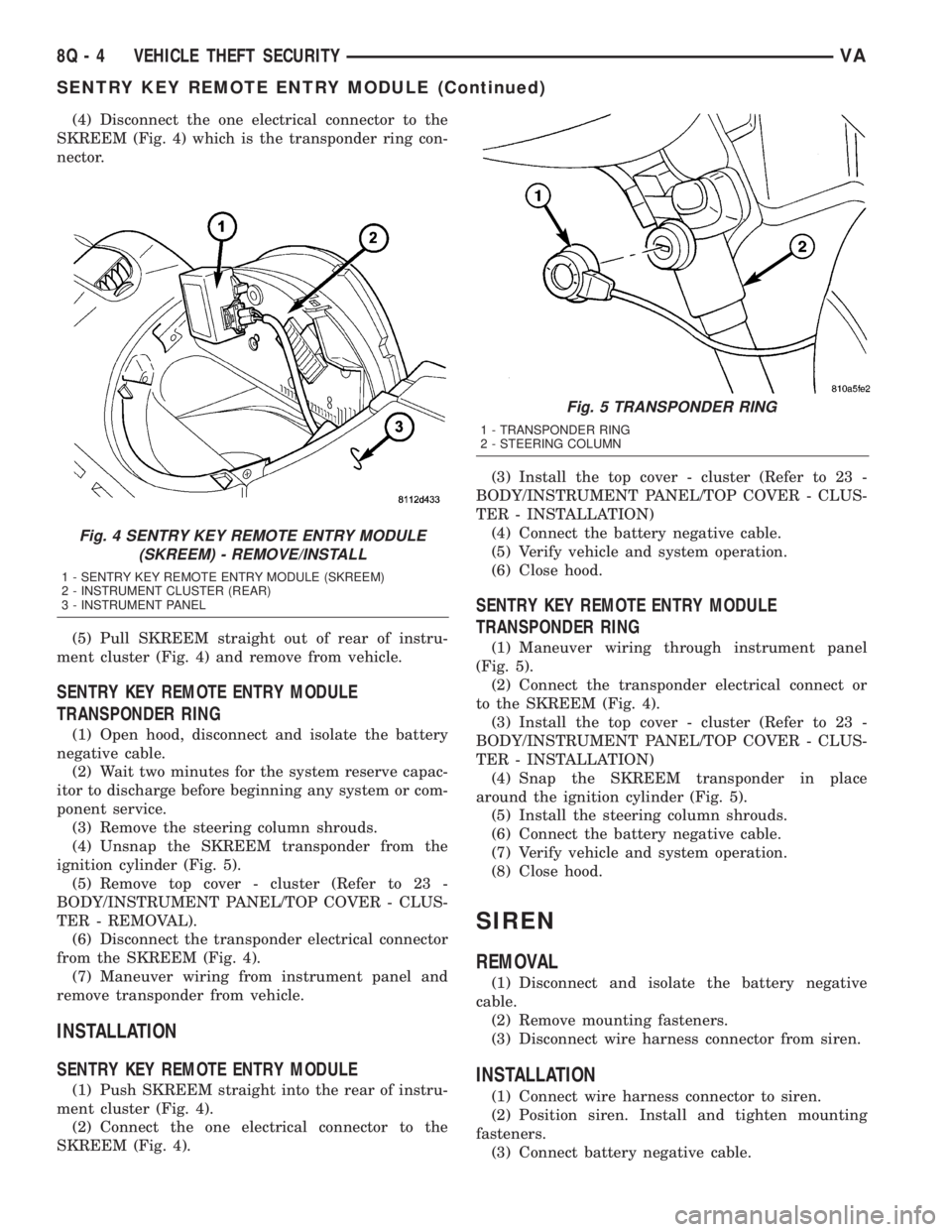
(4) Disconnect the one electrical connector to the
SKREEM (Fig. 4) which is the transponder ring con-
nector.
(5) Pull SKREEM straight out of rear of instru-
ment cluster (Fig. 4) and remove from vehicle.
SENTRY KEY REMOTE ENTRY MODULE
TRANSPONDER RING
(1) Open hood, disconnect and isolate the battery
negative cable.
(2) Wait two minutes for the system reserve capac-
itor to discharge before beginning any system or com-
ponent service.
(3) Remove the steering column shrouds.
(4) Unsnap the SKREEM transponder from the
ignition cylinder (Fig. 5).
(5) Remove top cover - cluster (Refer to 23 -
BODY/INSTRUMENT PANEL/TOP COVER - CLUS-
TER - REMOVAL).
(6) Disconnect the transponder electrical connector
from the SKREEM (Fig. 4).
(7) Maneuver wiring from instrument panel and
remove transponder from vehicle.
INSTALLATION
SENTRY KEY REMOTE ENTRY MODULE
(1) Push SKREEM straight into the rear of instru-
ment cluster (Fig. 4).
(2) Connect the one electrical connector to the
SKREEM (Fig. 4).(3) Install the top cover - cluster (Refer to 23 -
BODY/INSTRUMENT PANEL/TOP COVER - CLUS-
TER - INSTALLATION)
(4) Connect the battery negative cable.
(5) Verify vehicle and system operation.
(6) Close hood.
SENTRY KEY REMOTE ENTRY MODULE
TRANSPONDER RING
(1) Maneuver wiring through instrument panel
(Fig. 5).
(2) Connect the transponder electrical connect or
to the SKREEM (Fig. 4).
(3) Install the top cover - cluster (Refer to 23 -
BODY/INSTRUMENT PANEL/TOP COVER - CLUS-
TER - INSTALLATION)
(4) Snap the SKREEM transponder in place
around the ignition cylinder (Fig. 5).
(5) Install the steering column shrouds.
(6) Connect the battery negative cable.
(7) Verify vehicle and system operation.
(8) Close hood.
SIREN
REMOVAL
(1) Disconnect and isolate the battery negative
cable.
(2) Remove mounting fasteners.
(3) Disconnect wire harness connector from siren.
INSTALLATION
(1) Connect wire harness connector to siren.
(2) Position siren. Install and tighten mounting
fasteners.
(3) Connect battery negative cable.
Fig. 4 SENTRY KEY REMOTE ENTRY MODULE
(SKREEM) - REMOVE/INSTALL
1 - SENTRY KEY REMOTE ENTRY MODULE (SKREEM)
2 - INSTRUMENT CLUSTER (REAR)
3 - INSTRUMENT PANEL
Fig. 5 TRANSPONDER RING
1 - TRANSPONDER RING
2 - STEERING COLUMN
8Q - 4 VEHICLE THEFT SECURITYVA
SENTRY KEY REMOTE ENTRY MODULE (Continued)
Page 285 of 1232
The longer blade is installed on the left (driver) side
of the windshield.
²Wiper Linkage- The wiper pivots are the only
visible components of the wiper linkage. The remain-
der of the linkage is concealed within the engine
compartment just behind the hood opening. The
wiper linkage module includes the two wiper drive
links, the wiper motor crank arm, the two wiper piv-
ots, and the linkage and motor mounting bracket.
²Wiper Motor- The wiper motor is secured to
the wiper linkage module bracket on the underside of
the cowl panel within the engine compartment. The
wiper motor output shaft and crank arm extend
through a clearance hole in the mounting bracket,
where they are connected to a crank arm that drives
the wiper linkage.
²Wiper Relay- The wiper relay is located in a
dedicated receptacle on the lower left surface of the
fuse block underneath the steering column behind
the fuse access panel and the steering column open-
ing panel.
²Wiper, Turn Signals, Engine Start Control
Module- The wiper, turn signals and engine start
control module is integral to the fuse block located
underneath the steering column. The fuse block is
concealed behind the fuse access panel and the steer-
ing column opening panel, where it is secured with
screws to the steering column. The wiper, turn sig-
nals and engine start control module contains the
intermittent wipe logic circuitry, which includes
active electronic elements that allow it to provide the
intermittent wipe delay and the wipe-after-wash fea-
tures of the intermittent wipe system based upon
numerous hard wired inputs, then provides the
proper programmed hard wired control output to
operate the wiper motor through the wiper relay.
Hard wired circuitry connects the wiper and
washer system components to the electrical system of
the vehicle. These hard wired circuits are integral to
several wire harnesses, which are routed throughout
the vehicle and retained by many different methods.
These circuits may be connected to each other, to the
vehicle electrical system and to the wiper and washer
system components through the use of a combination
of soldered splices, splice block connectors, and many
different types of wire harness terminal connectors
and insulators. Refer to the appropriate wiring infor-
mation. The wiring information includes wiring dia-
grams, proper wire and connector repair procedures,
further details on wire harness routing and reten-
tion, as well as pin-out and location views for the
various wire harness connectors, splices and grounds.OPERATING MODES
The components of the wiper and washer system
are designed to provide the following operating
modes:
²Continuous Wipe Mode- The two-speed wiper
motor, the internal circuitry of the multi-function
switch, and the wiper relay work in concert to pro-
vide two continuous wipe cycles, low speed or high
speed.
²Intermittent Wipe Mode- The internal cir-
cuitry of the multi-function switch, the intermittent
wipe circuitry of the wiper, turn signals and engine
start control module in the fuse block, and the wiper
relay work in concert to provide an intermittent wipe
mode with a single, fixed delay interval.
²Pulse Wipe Mode- The internal circuitry of
the multi-function switch and the wiper relay work
in concert to provide a pulse wipe mode that will
allow the wiper motor to be operated for a single,
complete wipe cycle.
²Washer Mode- When the washer system is
activated with the multi-function switch while the
wiper system is operating, washer fluid will be dis-
pensed onto the windshield glass through the washer
nozzles for as long as the washer pump/motor is
energized.
²Wipe-After-Wash Mode- The intermittent
wipe circuitry of the wiper, turn signals and engine
start control module in the fuse block, and the wiper
relay provide a wipe-after-wash feature. If the wipers
are turned Off, this feature will operate the washer
pump/motor and the wipers for as long as the washer
system is activated, then provide several additional
wipe cycles after the washer system is deactivated
before parking the wiper blades near the base of the
windshield.
OPERATION
The wiper and washer system is designed to pro-
vide the vehicle operator with a convenient, safe, and
reliable means of maintaining visibility through the
windshield glass. The various components of this sys-
tem are designed to convert electrical energy pro-
duced by the vehicle electrical system into the
mechanical action of the wiper blades to wipe the
outside surface of the glass, as well as into the
hydraulic action of the washer system to apply
washer fluid stored in an on-board reservoir to the
area of the glass to be wiped. When combined, these
components provide the means to effectively main-
tain clear visibility for the vehicle operator by remov-
ing excess accumulations of rain, snow, bugs, mud, or
other minor debris from the outside windshield glass
surface that might be encountered while driving the
vehicle under numerous types of inclement operating
conditions.
VAWIPERS/WASHERS 8R - 3
WIPERS/WASHERS (Continued)
Page 289 of 1232
CHECK VALVE
DESCRIPTION
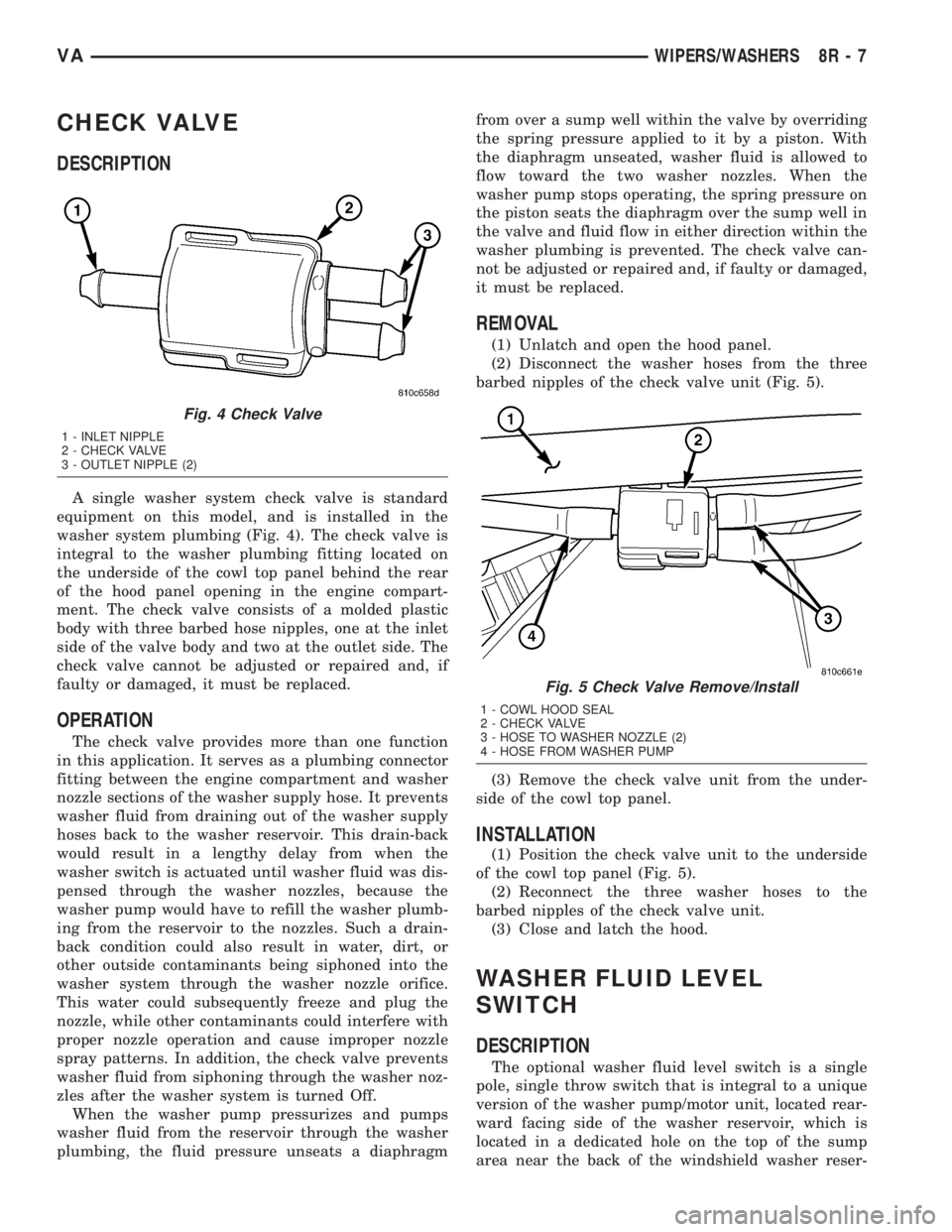
A single washer system check valve is standard
equipment on this model, and is installed in the
washer system plumbing (Fig. 4). The check valve is
integral to the washer plumbing fitting located on
the underside of the cowl top panel behind the rear
of the hood panel opening in the engine compart-
ment. The check valve consists of a molded plastic
body with three barbed hose nipples, one at the inlet
side of the valve body and two at the outlet side. The
check valve cannot be adjusted or repaired and, if
faulty or damaged, it must be replaced.
OPERATION
The check valve provides more than one function
in this application. It serves as a plumbing connector
fitting between the engine compartment and washer
nozzle sections of the washer supply hose. It prevents
washer fluid from draining out of the washer supply
hoses back to the washer reservoir. This drain-back
would result in a lengthy delay from when the
washer switch is actuated until washer fluid was dis-
pensed through the washer nozzles, because the
washer pump would have to refill the washer plumb-
ing from the reservoir to the nozzles. Such a drain-
back condition could also result in water, dirt, or
other outside contaminants being siphoned into the
washer system through the washer nozzle orifice.
This water could subsequently freeze and plug the
nozzle, while other contaminants could interfere with
proper nozzle operation and cause improper nozzle
spray patterns. In addition, the check valve prevents
washer fluid from siphoning through the washer noz-
zles after the washer system is turned Off.
When the washer pump pressurizes and pumps
washer fluid from the reservoir through the washer
plumbing, the fluid pressure unseats a diaphragmfrom over a sump well within the valve by overriding
the spring pressure applied to it by a piston. With
the diaphragm unseated, washer fluid is allowed to
flow toward the two washer nozzles. When the
washer pump stops operating, the spring pressure on
the piston seats the diaphragm over the sump well in
the valve and fluid flow in either direction within the
washer plumbing is prevented. The check valve can-
not be adjusted or repaired and, if faulty or damaged,
it must be replaced.
REMOVAL
(1) Unlatch and open the hood panel.
(2) Disconnect the washer hoses from the three
barbed nipples of the check valve unit (Fig. 5).
(3) Remove the check valve unit from the under-
side of the cowl top panel.
INSTALLATION
(1) Position the check valve unit to the underside
of the cowl top panel (Fig. 5).
(2) Reconnect the three washer hoses to the
barbed nipples of the check valve unit.
(3) Close and latch the hood.
WASHER FLUID LEVEL
SWITCH
DESCRIPTION
The optional washer fluid level switch is a single
pole, single throw switch that is integral to a unique
version of the washer pump/motor unit, located rear-
ward facing side of the washer reservoir, which is
located in a dedicated hole on the top of the sump
area near the back of the windshield washer reser-
Fig. 4 Check Valve
1 - INLET NIPPLE
2 - CHECK VALVE
3 - OUTLET NIPPLE (2)
Fig. 5 Check Valve Remove/Install
1 - COWL HOOD SEAL
2 - CHECK VALVE
3 - HOSE TO WASHER NOZZLE (2)
4 - HOSE FROM WASHER PUMP
VAWIPERS/WASHERS 8R - 7
Page 290 of 1232
voir on the right front fender wheel house in the
engine compartment. Only a molded plastic nipple
with a clear vent tube are visible near the top of the
washer pump/motor unit that is equipped with the
optional fluid level switch when it is installed in the
reservoir. The vent tube is routed to and retained in
an integral clip located behind the reservoir filler cap
near the top of the reservoir. This version of the
washer pump/motor unit also has a third terminal
pin in its integral connector receptacle. The washer
fluid level switch cannot be adjusted or repaired. If
faulty or damaged, the entire washer pump/motor
unit must be replaced.
OPERATION
The washer fluid level switch monitors the level of
the washer fluid in the washer reservoir. When the
fluid level in the washer reservoir is at or above the
predetermined minimum, the switch contacts are
open. When the fluid level in the washer reservoir
falls below the predetermined minimum, the switch
contacts of the normally open switch close. The
washer fluid level switch is connected to the vehicle
electrical system through the washer pump/motor
unit take out and connector of the vehicle wire har-
ness. The switch receives a path to ground at all
times through another take out of the vehicle wire
harness with a single eyelet terminal connector that
is secured under a ground screw located near the
right headlamp in the engine compartment.The switch is connected in series between ground
and the washer fluid switch sense input to the Elec-
troMechanical Instrument Cluster (EMIC). When the
switch closes, the EMIC senses the ground on the
washer fluid switch sense circuit. The EMIC is pro-
grammed to respond to this input by illuminating the
washer fluid indicator. The washer fluid level switch
input to the EMIC may be diagnosed using conven-
tional diagnostic tools and methods.
WASHER HOSES/TUBES
DESCRIPTION
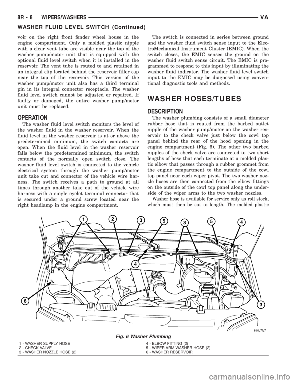
The washer plumbing consists of a small diameter
rubber hose that is routed from the barbed outlet
nipple of the washer pump/motor on the washer res-
ervoir to the check valve just below the cowl top
panel behind the rear of the hood opening in the
engine compartment (Fig. 6). The other two barbed
nipples of the check valve are connected to two short
lengths of hose that each terminate at a molded plas-
tic elbow that passes through a rubber grommet from
the engine compartment to the outside of the cowl
top panel near each wiper pivot. The two washer noz-
zle hoses are then connected from the elbow fittings
on the outside of the cowl top panel along the under-
side of the wiper arms to the two washer nozzles.
Washer hose is available for service only as roll stock,
which must then be cut to length. The molded plastic
Fig. 6 Washer Plumbing
1 - WASHER SUPPLY HOSE 4 - ELBOW FITTING (2)
2 - CHECK VALVE 5 - WIPER ARM WASHER HOSE (2)
3 - WASHER NOZZLE HOSE (2) 6 - WASHER RESERVOIR
8R - 8 WIPERS/WASHERSVA
WASHER FLUID LEVEL SWITCH (Continued)
Page 1088 of 1232
HOOD
TABLE OF CONTENTS
page page
HINGE
REMOVAL.............................50
INSTALLATION.........................50
HOOD
REMOVAL.............................50
INSTALLATION.........................50
ADJUSTMENTS
ADJUSTMENT........................51
LATCH
REMOVAL.............................51
INSTALLATION.........................51
LATCH RELEASE CABLE
REMOVAL.............................51INSTALLATION.........................51
LATCH RELEASE HANDLE
REMOVAL.............................52
INSTALLATION.........................52
PROP ROD
REMOVAL.............................52
INSTALLATION.........................52
SAFETY LATCH
REMOVAL.............................52
INSTALLATION.........................52
HINGE
REMOVAL
NOTE: It is not necessary to remove the hood to
replace one or both hinges. The hinges can be
replaced one at a time.
(1) Open hood and support as needed.
(2) Using a grease pencil or equivalent, mark the
position of the hinge on the hood and cowl.
(3) Remove the two hood nuts.
(4) Remove the two cowl bolts and remove hinge.
INSTALLATION
(1) Position hinge on vehicle and align reference
marks.
(2) Install cowl bolts and tighten to 23 N´m (17 ft.
lbs.).
(3) Install hood nuts and tighten to 23 N´m (17 ft.
lbs.).
(4) Check and adjust hood if necessary. (Refer to
23 - BODY/HOOD/HOOD - ADJUSTMENTS)
HOOD
REMOVAL
(1) Raise and support hood.
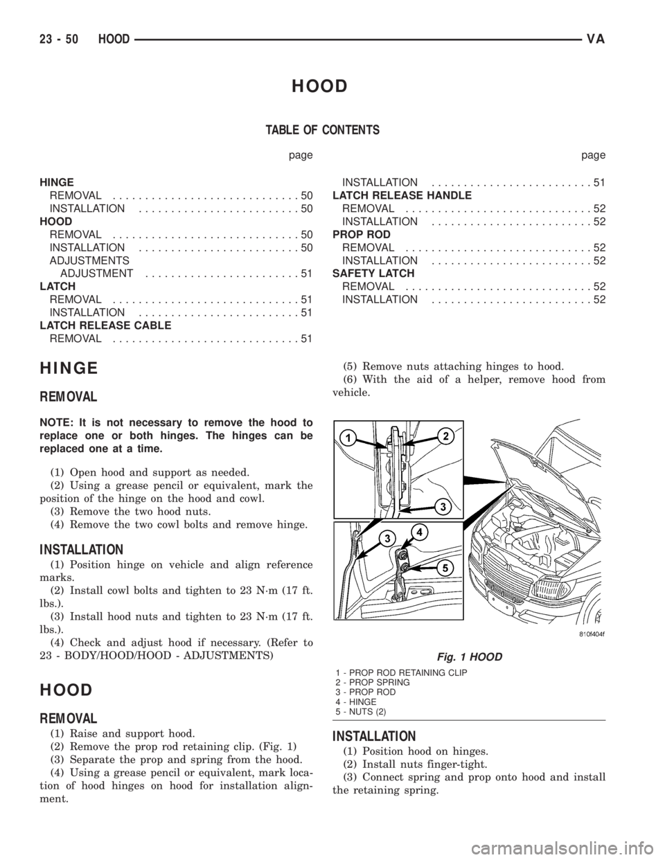
(2) Remove the prop rod retaining clip. (Fig. 1)
(3) Separate the prop and spring from the hood.
(4) Using a grease pencil or equivalent, mark loca-
tion of hood hinges on hood for installation align-
ment.(5) Remove nuts attaching hinges to hood.
(6) With the aid of a helper, remove hood from
vehicle.INSTALLATION
(1) Position hood on hinges.
(2) Install nuts finger-tight.
(3) Connect spring and prop onto hood and install
the retaining spring.
Fig. 1 HOOD
1 - PROP ROD RETAINING CLIP
2 - PROP SPRING
3 - PROP ROD
4 - HINGE
5 - NUTS (2)
23 - 50 HOODVA
Page 1090 of 1232
LATCH RELEASE HANDLE
REMOVAL
(1) Remove the screws and remove the release
handle.
(2) Disconnect the cable from handle.
INSTALLATION
(1) Connect latch cable to release handle.
(2) Install handle and install the screws.
PROP ROD
REMOVAL
(1) Open and support hood.
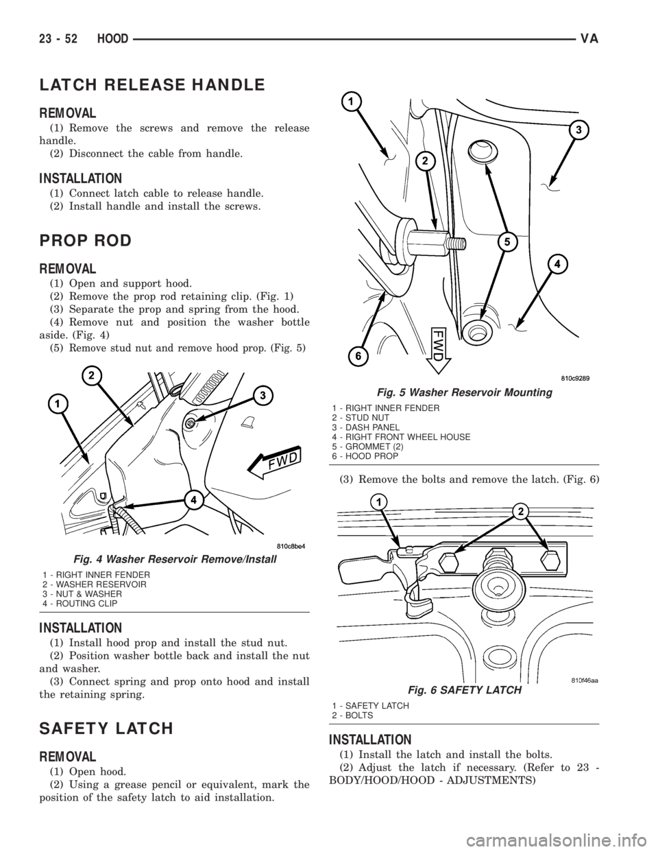
(2) Remove the prop rod retaining clip. (Fig. 1)
(3) Separate the prop and spring from the hood.
(4) Remove nut and position the washer bottle
aside. (Fig. 4)
(5)
Remove stud nut and remove hood prop. (Fig. 5)
INSTALLATION
(1) Install hood prop and install the stud nut.
(2) Position washer bottle back and install the nut
and washer.
(3) Connect spring and prop onto hood and install
the retaining spring.
SAFETY LATCH
REMOVAL
(1) Open hood.
(2) Using a grease pencil or equivalent, mark the
position of the safety latch to aid installation.(3) Remove the bolts and remove the latch. (Fig. 6)
INSTALLATION
(1) Install the latch and install the bolts.
(2) Adjust the latch if necessary. (Refer to 23 -
BODY/HOOD/HOOD - ADJUSTMENTS)
Fig. 4 Washer Reservoir Remove/Install
1 - RIGHT INNER FENDER
2 - WASHER RESERVOIR
3 - NUT & WASHER
4 - ROUTING CLIP
Fig. 5 Washer Reservoir Mounting
1 - RIGHT INNER FENDER
2 - STUD NUT
3 - DASH PANEL
4 - RIGHT FRONT WHEEL HOUSE
5 - GROMMET (2)
6 - HOOD PROP
Fig. 6 SAFETY LATCH
1 - SAFETY LATCH
2 - BOLTS
23 - 52 HOODVA
Page 1130 of 1232
²expansion valve
²air outlet temperature sensor
²mode doors
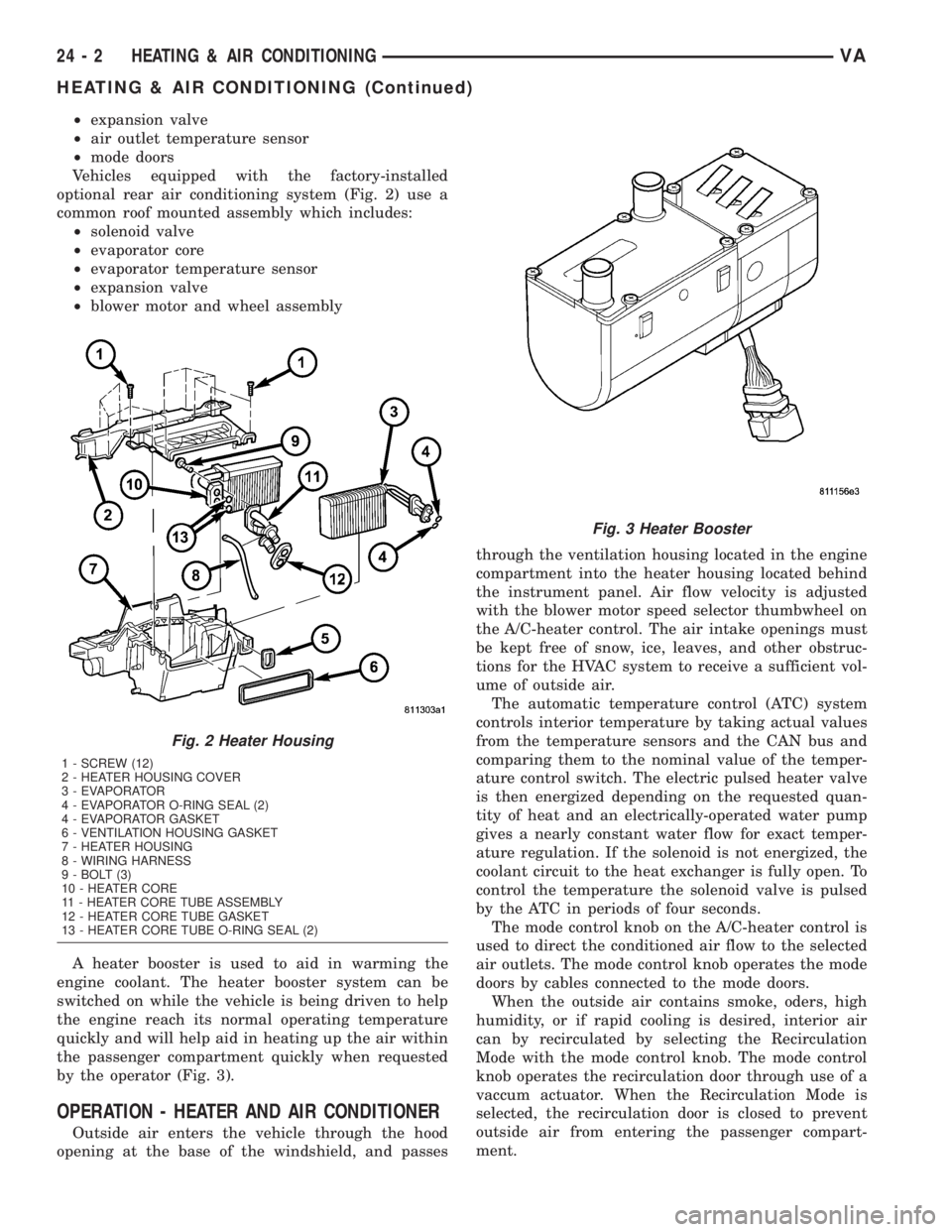
Vehicles equipped with the factory-installed
optional rear air conditioning system (Fig. 2) use a
common roof mounted assembly which includes:
²solenoid valve
²evaporator core
²evaporator temperature sensor
²expansion valve
²blower motor and wheel assembly
A heater booster is used to aid in warming the
engine coolant. The heater booster system can be
switched on while the vehicle is being driven to help
the engine reach its normal operating temperature
quickly and will help aid in heating up the air within
the passenger compartment quickly when requested
by the operator (Fig. 3).
OPERATION - HEATER AND AIR CONDITIONER
Outside air enters the vehicle through the hood
opening at the base of the windshield, and passesthrough the ventilation housing located in the engine
compartment into the heater housing located behind
the instrument panel. Air flow velocity is adjusted
with the blower motor speed selector thumbwheel on
the A/C-heater control. The air intake openings must
be kept free of snow, ice, leaves, and other obstruc-
tions for the HVAC system to receive a sufficient vol-
ume of outside air.
The automatic temperature control (ATC) system
controls interior temperature by taking actual values
from the temperature sensors and the CAN bus and
comparing them to the nominal value of the temper-
ature control switch. The electric pulsed heater valve
is then energized depending on the requested quan-
tity of heat and an electrically-operated water pump
gives a nearly constant water flow for exact temper-
ature regulation. If the solenoid is not energized, the
coolant circuit to the heat exchanger is fully open. To
control the temperature the solenoid valve is pulsed
by the ATC in periods of four seconds.
The mode control knob on the A/C-heater control is
used to direct the conditioned air flow to the selected
air outlets. The mode control knob operates the mode
doors by cables connected to the mode doors.
When the outside air contains smoke, oders, high
humidity, or if rapid cooling is desired, interior air
can by recirculated by selecting the Recirculation
Mode with the mode control knob. The mode control
knob operates the recirculation door through use of a
vaccum actuator. When the Recirculation Mode is
selected, the recirculation door is closed to prevent
outside air from entering the passenger compart-
ment.
Fig. 2 Heater Housing
1 - SCREW (12)
2 - HEATER HOUSING COVER
3 - EVAPORATOR
4 - EVAPORATOR O-RING SEAL (2)
4 - EVAPORATOR GASKET
6 - VENTILATION HOUSING GASKET
7 - HEATER HOUSING
8 - WIRING HARNESS
9 - BOLT (3)
10 - HEATER CORE
11 - HEATER CORE TUBE ASSEMBLY
12 - HEATER CORE TUBE GASKET
13 - HEATER CORE TUBE O-RING SEAL (2)
Fig. 3 Heater Booster
24 - 2 HEATING & AIR CONDITIONINGVA
HEATING & AIR CONDITIONING (Continued)
Page 1133 of 1232
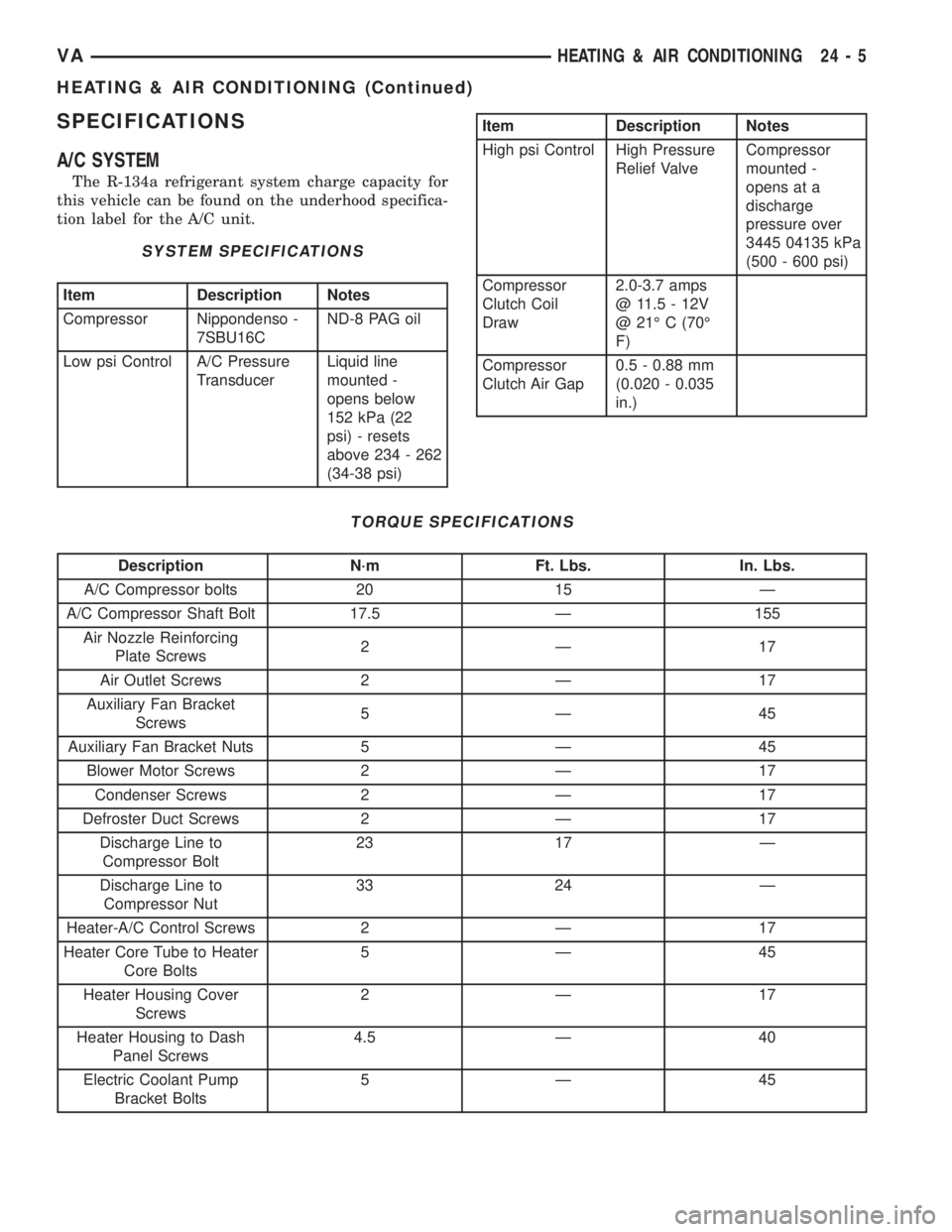
SPECIFICATIONS
A/C SYSTEM
The R-134a refrigerant system charge capacity for
this vehicle can be found on the underhood specifica-
tion label for the A/C unit.
SYSTEM SPECIFICATIONS
Item Description Notes
Compressor Nippondenso -
7SBU16CND-8 PAG oil
Low psi Control A/C Pressure
TransducerLiquid line
mounted -
opens below
152 kPa (22
psi) - resets
above 234 - 262
(34-38 psi)
Item Description Notes
High psi Control High Pressure
Relief ValveCompressor
mounted -
opens at a
discharge
pressure over
3445 04135 kPa
(500 - 600 psi)
Compressor
Clutch Coil
Draw2.0-3.7 amps
@ 11.5 - 12V
@ 21É C (70É
F)
Compressor
Clutch Air Gap0.5 - 0.88 mm
(0.020 - 0.035
in.)
TORQUE SPECIFICATIONS
Description N´m Ft. Lbs. In. Lbs.
A/C Compressor bolts 20 15 Ð
A/C Compressor Shaft Bolt 17.5 Ð 155
Air Nozzle Reinforcing
Plate Screws2Ð 17
Air Outlet Screws 2 Ð 17
Auxiliary Fan Bracket
Screws5Ð 45
Auxiliary Fan Bracket Nuts 5 Ð 45
Blower Motor Screws 2 Ð 17
Condenser Screws 2 Ð 17
Defroster Duct Screws 2 Ð 17
Discharge Line to
Compressor Bolt23 17 Ð
Discharge Line to
Compressor Nut33 24 Ð
Heater-A/C Control Screws 2 Ð 17
Heater Core Tube to Heater
Core Bolts5Ð 45
Heater Housing Cover
Screws2Ð 17
Heater Housing to Dash
Panel Screws4.5 Ð 40
Electric Coolant Pump
Bracket Bolts5Ð 45
VAHEATING & AIR CONDITIONING 24 - 5
HEATING & AIR CONDITIONING (Continued)