2005 MERCEDES-BENZ SPRINTER four wheel drive
[x] Cancel search: four wheel drivePage 265 of 1232
PASSENGER AIRBAG
BRACKET
REMOVAL
WARNING: ON VEHICLES EQUIPPED WITH AIR-
BAGS, DISABLE THE SUPPLEMENTAL RESTRAINT
SYSTEM BEFORE ATTEMPTING ANY STEERING
WHEEL, STEERING COLUMN, DRIVER AIRBAG,
PASSENGER AIRBAG, SEAT BELT TENSIONER, OR
INSTRUMENT PANEL COMPONENT DIAGNOSIS OR
SERVICE. DISCONNECT AND ISOLATE THE BAT-
TERY NEGATIVE (GROUND) CABLE, THEN WAIT
TWO MINUTES FOR THE SYSTEM CAPACITOR TO
DISCHARGE BEFORE PERFORMING FURTHER
DIAGNOSIS OR SERVICE. THIS IS THE ONLY SURE
WAY TO DISABLE THE SUPPLEMENTAL
RESTRAINT SYSTEM. FAILURE TO TAKE THE
PROPER PRECAUTIONS COULD RESULT IN ACCI-
DENTAL AIRBAG DEPLOYMENT AND POSSIBLE
PERSONAL INJURY.
(1) Remove the passenger airbag from the instru-
ment panel. (Refer to 8 - ELECTRICAL/RE-
STRAINTS/PASSENGER AIRBAG - REMOVAL).
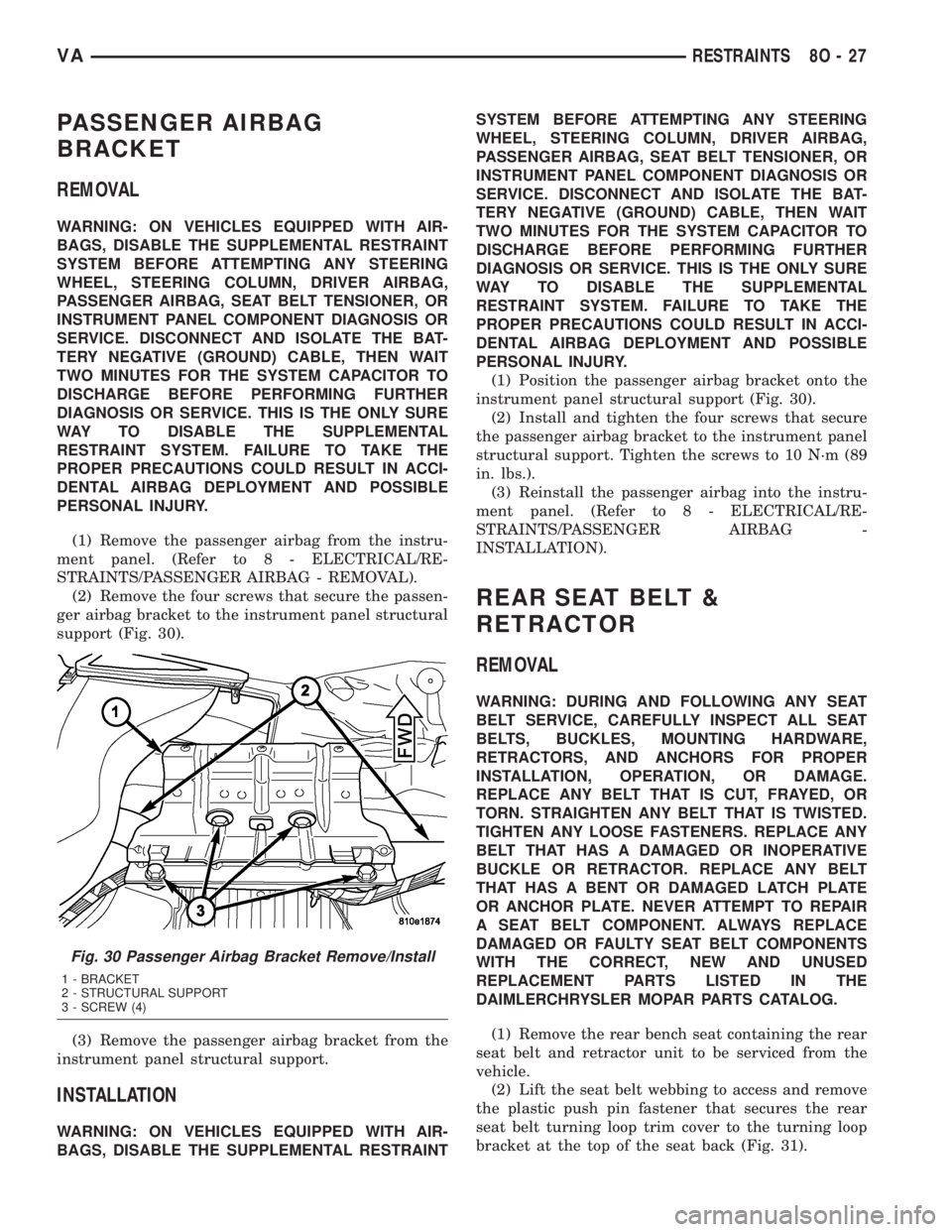
(2) Remove the four screws that secure the passen-
ger airbag bracket to the instrument panel structural
support (Fig. 30).
(3) Remove the passenger airbag bracket from the
instrument panel structural support.
INSTALLATION
WARNING: ON VEHICLES EQUIPPED WITH AIR-
BAGS, DISABLE THE SUPPLEMENTAL RESTRAINTSYSTEM BEFORE ATTEMPTING ANY STEERING
WHEEL, STEERING COLUMN, DRIVER AIRBAG,
PASSENGER AIRBAG, SEAT BELT TENSIONER, OR
INSTRUMENT PANEL COMPONENT DIAGNOSIS OR
SERVICE. DISCONNECT AND ISOLATE THE BAT-
TERY NEGATIVE (GROUND) CABLE, THEN WAIT
TWO MINUTES FOR THE SYSTEM CAPACITOR TO
DISCHARGE BEFORE PERFORMING FURTHER
DIAGNOSIS OR SERVICE. THIS IS THE ONLY SURE
WAY TO DISABLE THE SUPPLEMENTAL
RESTRAINT SYSTEM. FAILURE TO TAKE THE
PROPER PRECAUTIONS COULD RESULT IN ACCI-
DENTAL AIRBAG DEPLOYMENT AND POSSIBLE
PERSONAL INJURY.
(1) Position the passenger airbag bracket onto the
instrument panel structural support (Fig. 30).
(2) Install and tighten the four screws that secure
the passenger airbag bracket to the instrument panel
structural support. Tighten the screws to 10 N´m (89
in. lbs.).
(3) Reinstall the passenger airbag into the instru-
ment panel. (Refer to 8 - ELECTRICAL/RE-
STRAINTS/PASSENGER AIRBAG -
INSTALLATION).
REAR SEAT BELT &
RETRACTOR
REMOVAL
WARNING: DURING AND FOLLOWING ANY SEAT
BELT SERVICE, CAREFULLY INSPECT ALL SEAT
BELTS, BUCKLES, MOUNTING HARDWARE,
RETRACTORS, AND ANCHORS FOR PROPER
INSTALLATION, OPERATION, OR DAMAGE.
REPLACE ANY BELT THAT IS CUT, FRAYED, OR
TORN. STRAIGHTEN ANY BELT THAT IS TWISTED.
TIGHTEN ANY LOOSE FASTENERS. REPLACE ANY
BELT THAT HAS A DAMAGED OR INOPERATIVE
BUCKLE OR RETRACTOR. REPLACE ANY BELT
THAT HAS A BENT OR DAMAGED LATCH PLATE
OR ANCHOR PLATE. NEVER ATTEMPT TO REPAIR
A SEAT BELT COMPONENT. ALWAYS REPLACE
DAMAGED OR FAULTY SEAT BELT COMPONENTS
WITH THE CORRECT, NEW AND UNUSED
REPLACEMENT PARTS LISTED IN THE
DAIMLERCHRYSLER MOPAR PARTS CATALOG.
(1) Remove the rear bench seat containing the rear
seat belt and retractor unit to be serviced from the
vehicle.
(2) Lift the seat belt webbing to access and remove
the plastic push pin fastener that secures the rear
seat belt turning loop trim cover to the turning loop
bracket at the top of the seat back (Fig. 31).
Fig. 30 Passenger Airbag Bracket Remove/Install
1 - BRACKET
2 - STRUCTURAL SUPPORT
3 - SCREW (4)
VARESTRAINTS 8O - 27
Page 879 of 1232
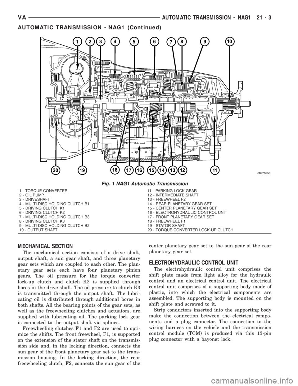
MECHANICAL SECTION
The mechanical section consists of a drive shaft,
output shaft, a sun gear shaft, and three planetary
gear sets which are coupled to each other. The plan-
etary gear sets each have four planetary pinion
gears. The oil pressure for the torque converter
lock-up clutch and clutch K2 is supplied through
bores in the drive shaft. The oil pressure to clutch K3
is transmitted through the output shaft. The lubri-
cating oil is distributed through additional bores in
both shafts. All the bearing points of the gear sets, as
well as the freewheeling clutches and actuators, are
supplied with lubricating oil. The parking lock gear
is connected to the output shaft via splines.
Freewheeling clutches F1 and F2 are used to opti-
mize the shifts. The front freewheel, F1, is supported
on the extension of the stator shaft on the transmis-
sion side and, in the locking direction, connects the
sun gear of the front planetary gear set to the trans-
mission housing. In the locking direction, the rear
freewheeling clutch, F2, connects the sun gear of thecenter planetary gear set to the sun gear of the rear
planetary gear set.
ELECTROHYDRAULIC CONTROL UNIT
The electrohydraulic control unit comprises the
shift plate made from light alloy for the hydraulic
control and an electrical control unit. The electrical
control unit comprises of a supporting body made of
plastic, into which the electrical components are
assembled. The supporting body is mounted on the
shift plate and screwed to it.
Strip conductors inserted into the supporting body
make the connection between the electrical compo-
nents and a plug connector. The connection to the
wiring harness on the vehicle and the transmission
control module (TCM) is produced via this 13-pin
plug connector with a bayonet lock.
Fig. 1 NAG1 Automatic Transmission
1 - TORQUE CONVERTER 11 - PARKING LOCK GEAR
2 - OIL PUMP 12 - INTERMEDIATE SHAFT
3 - DRIVESHAFT 13 - FREEWHEEL F2
4 - MULTI-DISC HOLDING CLUTCH B1 14 - REAR PLANETARY GEAR SET
5 - DRIVING CLUTCH K1 15 - CENTER PLANETARY GEAR SET
6 - DRIVING CLUTCH K2 16 - ELECTROHYDRAULIC CONTROL UNIT
7 - MULTI-DISC HOLDING CLUTCH B3 17 - FRONT PLANETARY GEAR SET
8 - DRIVING CLUTCH K3 18 - FREEWHEEL F1
9 - MULTI-DISC HOLDING CLUTCH B2 19 - STATOR SHAFT
10 - OUTPUT SHAFT 20 - TORQUE CONVERTER LOCK-UP CLUTCH
VAAUTOMATIC TRANSMISSION - NAG1 21 - 3
AUTOMATIC TRANSMISSION - NAG1 (Continued)
Page 887 of 1232
FOURTH GEAR POWERFLOW
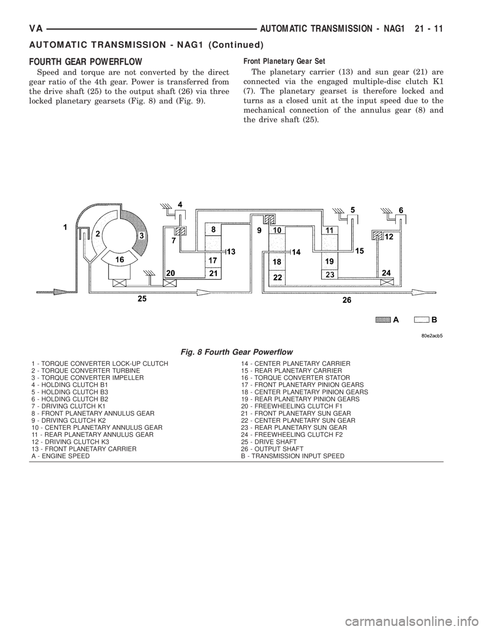
Speed and torque are not converted by the direct
gear ratio of the 4th gear. Power is transferred from
the drive shaft (25) to the output shaft (26) via three
locked planetary gearsets (Fig. 8) and (Fig. 9).Front Planetary Gear Set
The planetary carrier (13) and sun gear (21) are
connected via the engaged multiple-disc clutch K1
(7). The planetary gearset is therefore locked and
turns as a closed unit at the input speed due to the
mechanical connection of the annulus gear (8) and
the drive shaft (25).
Fig. 8 Fourth Gear Powerflow
1 - TORQUE CONVERTER LOCK-UP CLUTCH 14 - CENTER PLANETARY CARRIER
2 - TORQUE CONVERTER TURBINE 15 - REAR PLANETARY CARRIER
3 - TORQUE CONVERTER IMPELLER 16 - TORQUE CONVERTER STATOR
4 - HOLDING CLUTCH B1 17 - FRONT PLANETARY PINION GEARS
5 - HOLDING CLUTCH B3 18 - CENTER PLANETARY PINION GEARS
6 - HOLDING CLUTCH B2 19 - REAR PLANETARY PINION GEARS
7 - DRIVING CLUTCH K1 20 - FREEWHEELING CLUTCH F1
8 - FRONT PLANETARY ANNULUS GEAR 21 - FRONT PLANETARY SUN GEAR
9 - DRIVING CLUTCH K2 22 - CENTER PLANETARY SUN GEAR
10 - CENTER PLANETARY ANNULUS GEAR 23 - REAR PLANETARY SUN GEAR
11 - REAR PLANETARY ANNULUS GEAR 24 - FREEWHEELING CLUTCH F2
12 - DRIVING CLUTCH K3 25 - DRIVE SHAFT
13 - FRONT PLANETARY CARRIER 26 - OUTPUT SHAFT
A - ENGINE SPEED B - TRANSMISSION INPUT SPEED
VAAUTOMATIC TRANSMISSION - NAG1 21 - 11
AUTOMATIC TRANSMISSION - NAG1 (Continued)
Page 888 of 1232
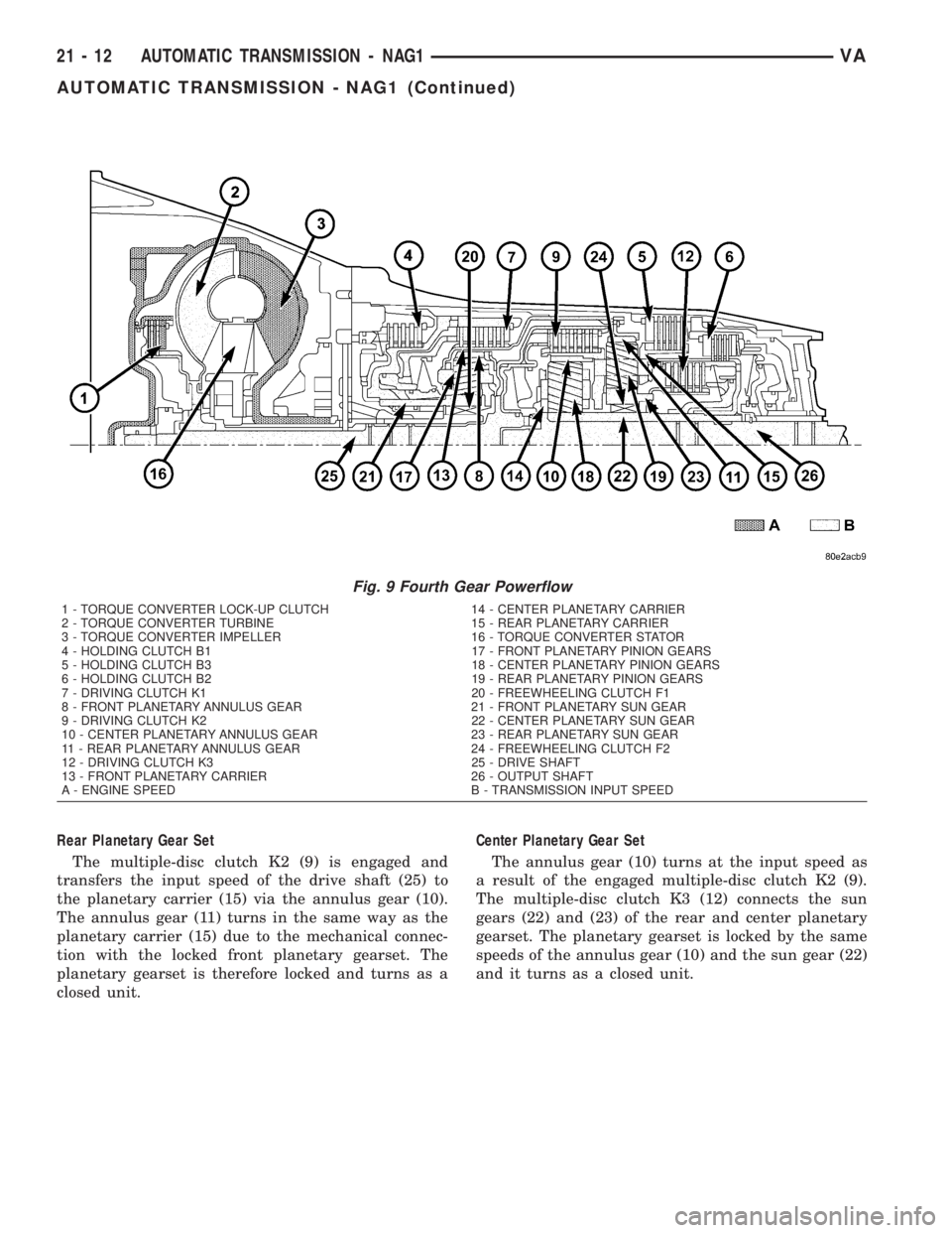
Rear Planetary Gear Set
The multiple-disc clutch K2 (9) is engaged and
transfers the input speed of the drive shaft (25) to
the planetary carrier (15) via the annulus gear (10).
The annulus gear (11) turns in the same way as the
planetary carrier (15) due to the mechanical connec-
tion with the locked front planetary gearset. The
planetary gearset is therefore locked and turns as a
closed unit.Center Planetary Gear Set
The annulus gear (10) turns at the input speed as
a result of the engaged multiple-disc clutch K2 (9).
The multiple-disc clutch K3 (12) connects the sun
gears (22) and (23) of the rear and center planetary
gearset. The planetary gearset is locked by the same
speeds of the annulus gear (10) and the sun gear (22)
and it turns as a closed unit.
Fig. 9 Fourth Gear Powerflow
1 - TORQUE CONVERTER LOCK-UP CLUTCH 14 - CENTER PLANETARY CARRIER
2 - TORQUE CONVERTER TURBINE 15 - REAR PLANETARY CARRIER
3 - TORQUE CONVERTER IMPELLER 16 - TORQUE CONVERTER STATOR
4 - HOLDING CLUTCH B1 17 - FRONT PLANETARY PINION GEARS
5 - HOLDING CLUTCH B3 18 - CENTER PLANETARY PINION GEARS
6 - HOLDING CLUTCH B2 19 - REAR PLANETARY PINION GEARS
7 - DRIVING CLUTCH K1 20 - FREEWHEELING CLUTCH F1
8 - FRONT PLANETARY ANNULUS GEAR 21 - FRONT PLANETARY SUN GEAR
9 - DRIVING CLUTCH K2 22 - CENTER PLANETARY SUN GEAR
10 - CENTER PLANETARY ANNULUS GEAR 23 - REAR PLANETARY SUN GEAR
11 - REAR PLANETARY ANNULUS GEAR 24 - FREEWHEELING CLUTCH F2
12 - DRIVING CLUTCH K3 25 - DRIVE SHAFT
13 - FRONT PLANETARY CARRIER 26 - OUTPUT SHAFT
A - ENGINE SPEED B - TRANSMISSION INPUT SPEED
21 - 12 AUTOMATIC TRANSMISSION - NAG1VA
AUTOMATIC TRANSMISSION - NAG1 (Continued)
Page 952 of 1232
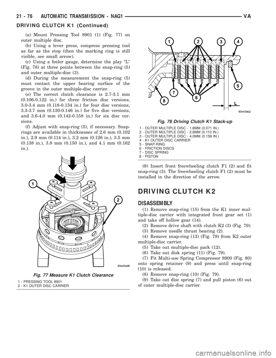
(a) Mount Pressing Tool 8901 (1) (Fig. 77) on
outer multiple disc.
(b) Using a lever press, compress pressing tool
as far as the stop (then the marking ring is still
visible, see small arrow).
(c) Using a feeler gauge, determine the play9L9
(Fig. 78) at three points between the snap-ring (5)
and outer multiple-disc (3).
(d) During the measurement the snap-ring (5)
must contact the upper bearing surface of the
groove in the outer multiple-disc carrier.
(e) The correct clutch clearance is 2.7-3.1 mm
(0.106-0.122 in.) for three friction disc versions,
3.0-3.4 mm (0.118-0.134 in.) for four disc versions,
3.3-3.7 mm (0.130-0.146 in.) for five disc versions,
and 3.6-4.0 mm (0.142-0.158 in.) for six disc ver-
sions.
(f) Adjust with snap-ring (5), if necessary. Snap-
rings are available in thicknesses of 2.6 mm (0.102
in.), 2.9 mm (0.114 in.), 3.2 mm (0.126 in.), 3.5 mm
(0.138 in.), 3.8 mm (0.150 in.), and 4.1 mm (0.162
in.).
(9) Insert front freewheeling clutch F1 (2) and fit
snap-ring (3). The freewheeling clutch F1 (2) must be
installed in the direction of the arrow.
DRIVING CLUTCH K2
DISASSEMBLY
(1) Remove snap-ring (15) from the K1 inner mul-
tiple-disc carrier with integrated front gear set (1)
and take off hollow gear (14).
(2) Remove drive shaft with clutch K2 (3) (Fig. 79).
(3) Remove needle thrust bearing (2).
(4) Remove snap-ring (13) (Fig. 79) from K2 outer
multiple-disc carrier.
(5) Take out multiple-disc pack (12).
(6) Take out disk spring (11) (Fig. 79).
(7) Fit Multi-use Spring Compressor 8900 (Fig. 80)
onto spring retainer (9) and press until snap-ring
(10) is released.
(8) Remove snap-ring (10) (Fig. 79).
(9) Take out disc spring (7) and pull piston (6) out
of outer multiple-disc carrier.
Fig. 77 Measure K1 Clutch Clearance
1 - PRESSING TOOL 8901
2 - K1 OUTER DISC CARRIER
Fig. 78 Driving Clutch K1 Stack-up
1 - OUTER MULTIPLE DISC - 1.8MM (0.071 IN.)
2 - OUTER MULTIPLE DISC - 2.8MM (0.110 IN.)
3 - OUTER MULTIPLE DISC - 4.0MM (0.158 IN.)
4 - K1 OUTER DISC CARRIER
5 - SNAP-RING
6 - FRICTION DISCS
7 - DISC SPRING
8 - PISTON
21 - 76 AUTOMATIC TRANSMISSION - NAG1VA
DRIVING CLUTCH K1 (Continued)
Page 954 of 1232
ASSEMBLY
(1) Install piston (6) (Fig. 81) in outer multiple-
disc carrier. Inspect seals (4 and 5), replace if neces-
sary. The rounded edges of the seals must point to
the outside.
(2) Insert disk spring (7) and spring retainer (9).
Insert disk spring (7) with curved side pointing
toward spring retainer (9). Inspect seal (8) (Fig. 81),
replace if necessary.
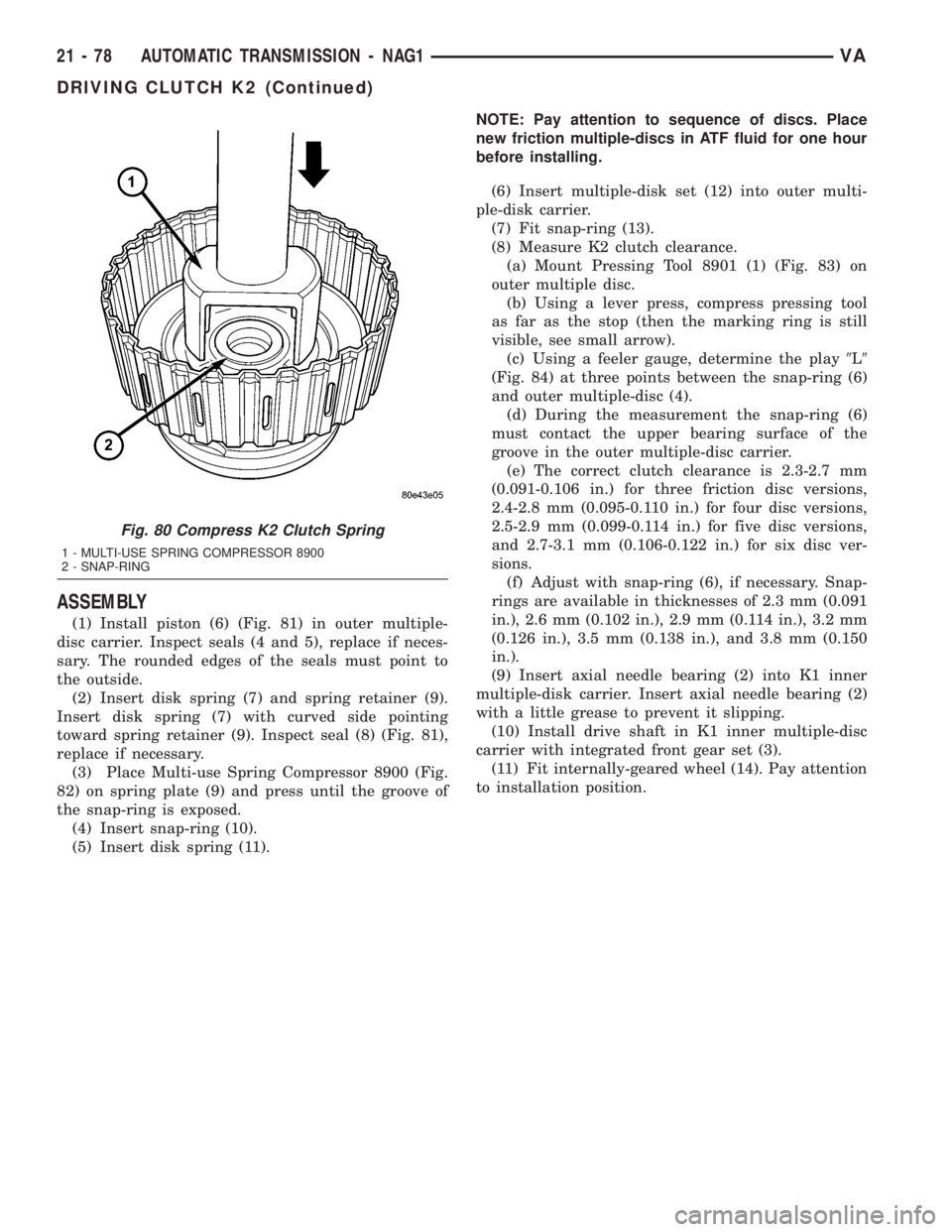
(3) Place Multi-use Spring Compressor 8900 (Fig.
82) on spring plate (9) and press until the groove of
the snap-ring is exposed.
(4) Insert snap-ring (10).
(5) Insert disk spring (11).NOTE: Pay attention to sequence of discs. Place
new friction multiple-discs in ATF fluid for one hour
before installing.
(6) Insert multiple-disk set (12) into outer multi-
ple-disk carrier.
(7) Fit snap-ring (13).
(8) Measure K2 clutch clearance.
(a) Mount Pressing Tool 8901 (1) (Fig. 83) on
outer multiple disc.
(b) Using a lever press, compress pressing tool
as far as the stop (then the marking ring is still
visible, see small arrow).
(c) Using a feeler gauge, determine the play9L9
(Fig. 84) at three points between the snap-ring (6)
and outer multiple-disc (4).
(d) During the measurement the snap-ring (6)
must contact the upper bearing surface of the
groove in the outer multiple-disc carrier.
(e) The correct clutch clearance is 2.3-2.7 mm
(0.091-0.106 in.) for three friction disc versions,
2.4-2.8 mm (0.095-0.110 in.) for four disc versions,
2.5-2.9 mm (0.099-0.114 in.) for five disc versions,
and 2.7-3.1 mm (0.106-0.122 in.) for six disc ver-
sions.
(f) Adjust with snap-ring (6), if necessary. Snap-
rings are available in thicknesses of 2.3 mm (0.091
in.), 2.6 mm (0.102 in.), 2.9 mm (0.114 in.), 3.2 mm
(0.126 in.), 3.5 mm (0.138 in.), and 3.8 mm (0.150
in.).
(9) Insert axial needle bearing (2) into K1 inner
multiple-disk carrier. Insert axial needle bearing (2)
with a little grease to prevent it slipping.
(10) Install drive shaft in K1 inner multiple-disc
carrier with integrated front gear set (3).
(11) Fit internally-geared wheel (14). Pay attention
to installation position.
Fig. 80 Compress K2 Clutch Spring
1 - MULTI-USE SPRING COMPRESSOR 8900
2 - SNAP-RING
21 - 78 AUTOMATIC TRANSMISSION - NAG1VA
DRIVING CLUTCH K2 (Continued)
Page 1022 of 1232
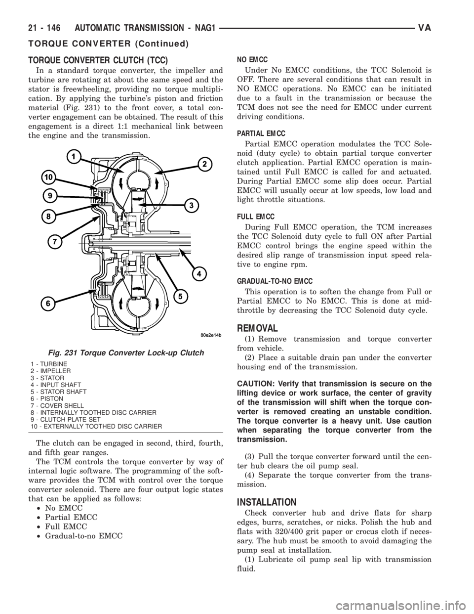
TORQUE CONVERTER CLUTCH (TCC)
In a standard torque converter, the impeller and
turbine are rotating at about the same speed and the
stator is freewheeling, providing no torque multipli-
cation. By applying the turbine's piston and friction
material (Fig. 231) to the front cover, a total con-
verter engagement can be obtained. The result of this
engagement is a direct 1:1 mechanical link between
the engine and the transmission.
The clutch can be engaged in second, third, fourth,
and fifth gear ranges.
The TCM controls the torque converter by way of
internal logic software. The programming of the soft-
ware provides the TCM with control over the torque
converter solenoid. There are four output logic states
that can be applied as follows:
²No EMCC
²Partial EMCC
²Full EMCC
²Gradual-to-no EMCCNO EMCC
Under No EMCC conditions, the TCC Solenoid is
OFF. There are several conditions that can result in
NO EMCC operations. No EMCC can be initiated
due to a fault in the transmission or because the
TCM does not see the need for EMCC under current
driving conditions.
PARTIAL EMCC
Partial EMCC operation modulates the TCC Sole-
noid (duty cycle) to obtain partial torque converter
clutch application. Partial EMCC operation is main-
tained until Full EMCC is called for and actuated.
During Partial EMCC some slip does occur. Partial
EMCC will usually occur at low speeds, low load and
light throttle situations.
FULL EMCC
During Full EMCC operation, the TCM increases
the TCC Solenoid duty cycle to full ON after Partial
EMCC control brings the engine speed within the
desired slip range of transmission input speed rela-
tive to engine rpm.
GRADUAL-TO-NO EMCC
This operation is to soften the change from Full or
Partial EMCC to No EMCC. This is done at mid-
throttle by decreasing the TCC Solenoid duty cycle.
REMOVAL
(1) Remove transmission and torque converter
from vehicle.
(2) Place a suitable drain pan under the converter
housing end of the transmission.
CAUTION: Verify that transmission is secure on the
lifting device or work surface, the center of gravity
of the transmission will shift when the torque con-
verter is removed creating an unstable condition.
The torque converter is a heavy unit. Use caution
when separating the torque converter from the
transmission.
(3) Pull the torque converter forward until the cen-
ter hub clears the oil pump seal.
(4) Separate the torque converter from the trans-
mission.
INSTALLATION
Check converter hub and drive flats for sharp
edges, burrs, scratches, or nicks. Polish the hub and
flats with 320/400 grit paper or crocus cloth if neces-
sary. The hub must be smooth to avoid damaging the
pump seal at installation.
(1) Lubricate oil pump seal lip with transmission
fluid.
Fig. 231 Torque Converter Lock-up Clutch
1 - TURBINE
2 - IMPELLER
3-STATOR
4 - INPUT SHAFT
5 - STATOR SHAFT
6 - PISTON
7 - COVER SHELL
8 - INTERNALLY TOOTHED DISC CARRIER
9 - CLUTCH PLATE SET
10 - EXTERNALLY TOOTHED DISC CARRIER
21 - 146 AUTOMATIC TRANSMISSION - NAG1VA
TORQUE CONVERTER (Continued)
Page 1030 of 1232
TIRES
DESCRIPTION
DESCRIPTION - TIRES
Tires are designed and engineered for each specific
vehicle. They provide the best overall performance
for normal operation. The ride and handling charac-
teristics match the vehicle's requirements. With
proper care they will give excellent reliability, trac-
tion, skid resistance, and tread life.
Driving habits have more effect on tire life than
any other factor. Careful drivers will obtain in most
cases, much greater mileage than severe use or care-
less drivers. A few of the driving habits which will
shorten the life of any tire are:
²Rapid acceleration
²Severe brake applications
²High speed driving
²Excessive speeds on turns
²Striking curbs and other obstacles
Radial-ply tires are more prone to irregular tread
wear. It is important to follow the tire rotation inter-
val shown in the section on Tire Rotation, (Refer to
22 - TIRES/WHEELS - STANDARD PROCEDURE).
This will help to achieve a greater tread life.
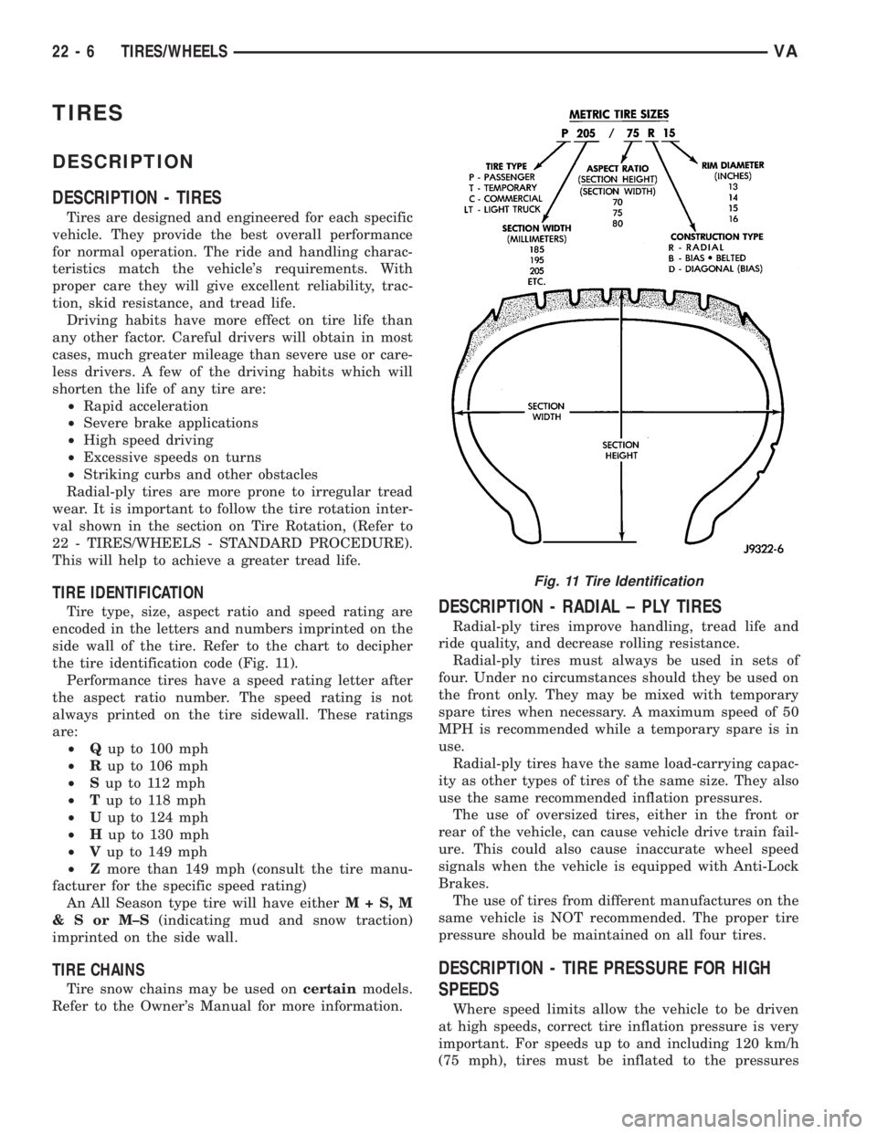
TIRE IDENTIFICATION
Tire type, size, aspect ratio and speed rating are
encoded in the letters and numbers imprinted on the
side wall of the tire. Refer to the chart to decipher
the tire identification code (Fig. 11).
Performance tires have a speed rating letter after
the aspect ratio number. The speed rating is not
always printed on the tire sidewall. These ratings
are:
²Qup to 100 mph
²Rup to 106 mph
²Sup to 112 mph
²Tup to 118 mph
²Uup to 124 mph
²Hup to 130 mph
²Vup to 149 mph
²Zmore than 149 mph (consult the tire manu-
facturer for the specific speed rating)
An All Season type tire will have eitherM+S,M
&SorM±S(indicating mud and snow traction)
imprinted on the side wall.
TIRE CHAINS
Tire snow chains may be used oncertainmodels.
Refer to the Owner's Manual for more information.
DESCRIPTION - RADIAL ± PLY TIRES
Radial-ply tires improve handling, tread life and
ride quality, and decrease rolling resistance.
Radial-ply tires must always be used in sets of
four. Under no circumstances should they be used on
the front only. They may be mixed with temporary
spare tires when necessary. A maximum speed of 50
MPH is recommended while a temporary spare is in
use.
Radial-ply tires have the same load-carrying capac-
ity as other types of tires of the same size. They also
use the same recommended inflation pressures.
The use of oversized tires, either in the front or
rear of the vehicle, can cause vehicle drive train fail-
ure. This could also cause inaccurate wheel speed
signals when the vehicle is equipped with Anti-Lock
Brakes.
The use of tires from different manufactures on the
same vehicle is NOT recommended. The proper tire
pressure should be maintained on all four tires.
DESCRIPTION - TIRE PRESSURE FOR HIGH
SPEEDS
Where speed limits allow the vehicle to be driven
at high speeds, correct tire inflation pressure is very
important. For speeds up to and including 120 km/h
(75 mph), tires must be inflated to the pressures
Fig. 11 Tire Identification
22 - 6 TIRES/WHEELSVA