2005 MERCEDES-BENZ SPRINTER airbag off
[x] Cancel search: airbag offPage 208 of 1232
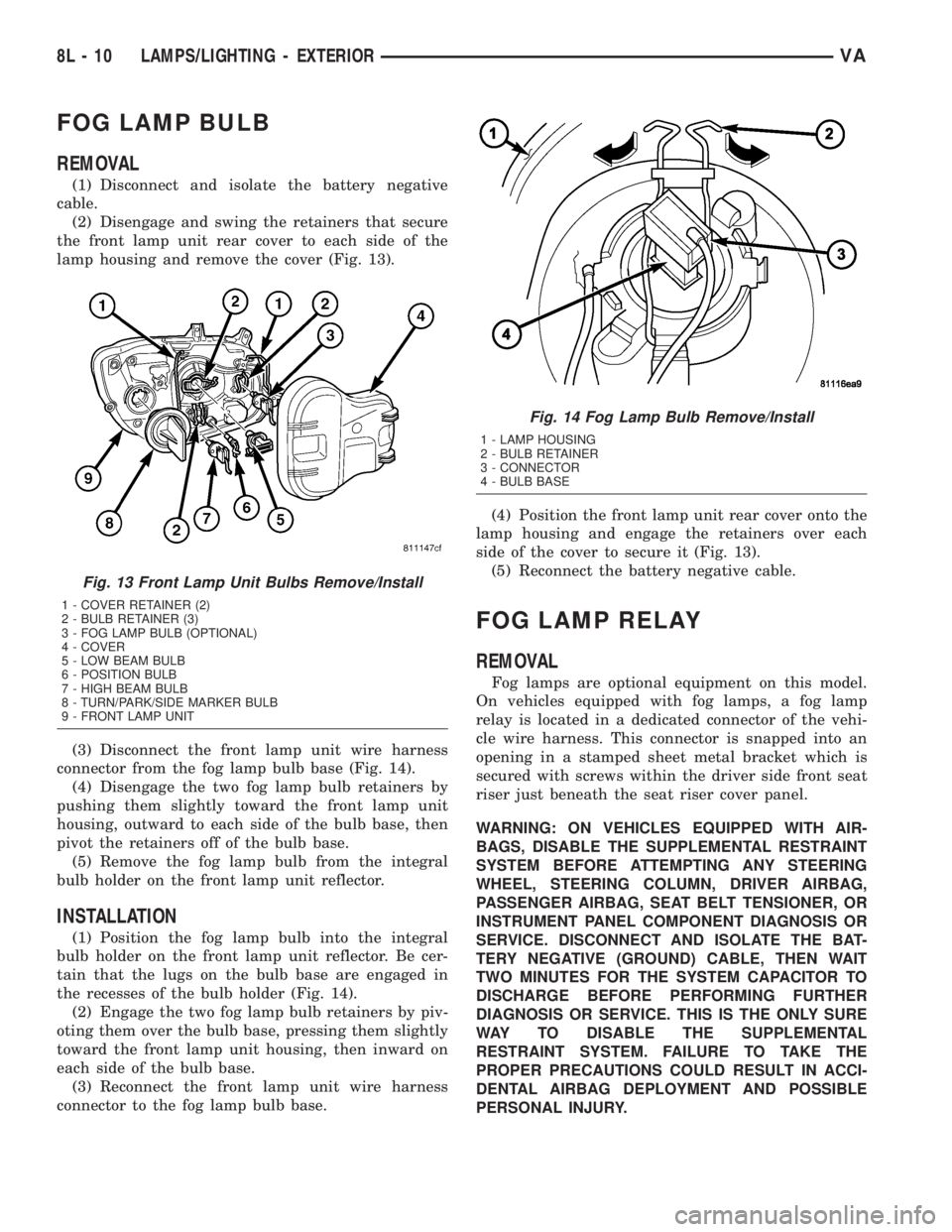
FOG LAMP BULB
REMOVAL
(1) Disconnect and isolate the battery negative
cable.
(2) Disengage and swing the retainers that secure
the front lamp unit rear cover to each side of the
lamp housing and remove the cover (Fig. 13).
(3) Disconnect the front lamp unit wire harness
connector from the fog lamp bulb base (Fig. 14).
(4) Disengage the two fog lamp bulb retainers by
pushing them slightly toward the front lamp unit
housing, outward to each side of the bulb base, then
pivot the retainers off of the bulb base.
(5) Remove the fog lamp bulb from the integral
bulb holder on the front lamp unit reflector.
INSTALLATION
(1) Position the fog lamp bulb into the integral
bulb holder on the front lamp unit reflector. Be cer-
tain that the lugs on the bulb base are engaged in
the recesses of the bulb holder (Fig. 14).
(2) Engage the two fog lamp bulb retainers by piv-
oting them over the bulb base, pressing them slightly
toward the front lamp unit housing, then inward on
each side of the bulb base.
(3) Reconnect the front lamp unit wire harness
connector to the fog lamp bulb base.(4) Position the front lamp unit rear cover onto the
lamp housing and engage the retainers over each
side of the cover to secure it (Fig. 13).
(5) Reconnect the battery negative cable.
FOG LAMP RELAY
REMOVAL
Fog lamps are optional equipment on this model.
On vehicles equipped with fog lamps, a fog lamp
relay is located in a dedicated connector of the vehi-
cle wire harness. This connector is snapped into an
opening in a stamped sheet metal bracket which is
secured with screws within the driver side front seat
riser just beneath the seat riser cover panel.
WARNING: ON VEHICLES EQUIPPED WITH AIR-
BAGS, DISABLE THE SUPPLEMENTAL RESTRAINT
SYSTEM BEFORE ATTEMPTING ANY STEERING
WHEEL, STEERING COLUMN, DRIVER AIRBAG,
PASSENGER AIRBAG, SEAT BELT TENSIONER, OR
INSTRUMENT PANEL COMPONENT DIAGNOSIS OR
SERVICE. DISCONNECT AND ISOLATE THE BAT-
TERY NEGATIVE (GROUND) CABLE, THEN WAIT
TWO MINUTES FOR THE SYSTEM CAPACITOR TO
DISCHARGE BEFORE PERFORMING FURTHER
DIAGNOSIS OR SERVICE. THIS IS THE ONLY SURE
WAY TO DISABLE THE SUPPLEMENTAL
RESTRAINT SYSTEM. FAILURE TO TAKE THE
PROPER PRECAUTIONS COULD RESULT IN ACCI-
DENTAL AIRBAG DEPLOYMENT AND POSSIBLE
PERSONAL INJURY.
Fig. 13 Front Lamp Unit Bulbs Remove/Install
1 - COVER RETAINER (2)
2 - BULB RETAINER (3)
3 - FOG LAMP BULB (OPTIONAL)
4 - COVER
5 - LOW BEAM BULB
6 - POSITION BULB
7 - HIGH BEAM BULB
8 - TURN/PARK/SIDE MARKER BULB
9 - FRONT LAMP UNIT
Fig. 14 Fog Lamp Bulb Remove/Install
1 - LAMP HOUSING
2 - BULB RETAINER
3 - CONNECTOR
4 - BULB BASE
8L - 10 LAMPS/LIGHTING - EXTERIORVA
Page 217 of 1232
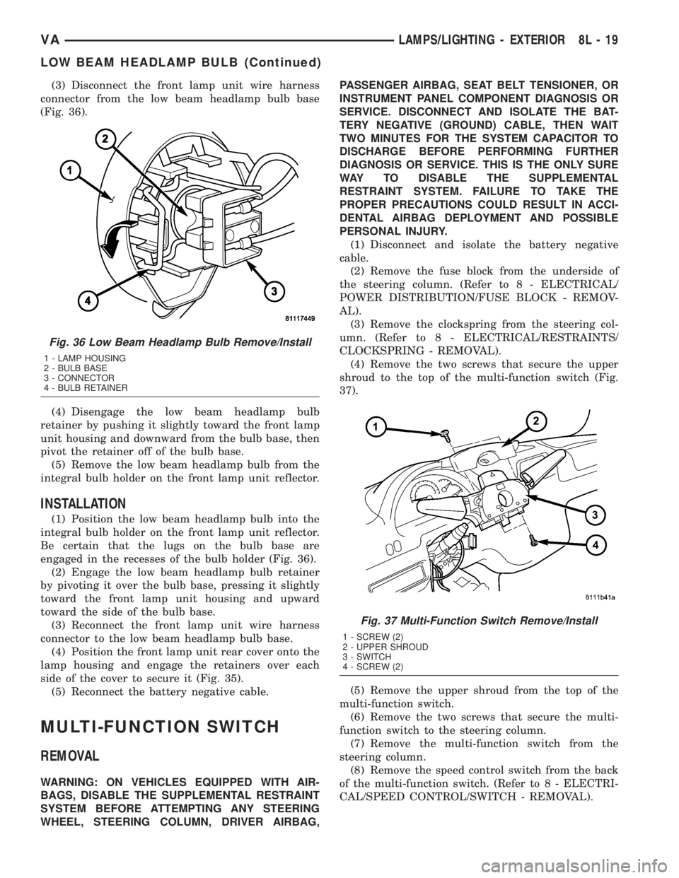
(3) Disconnect the front lamp unit wire harness
connector from the low beam headlamp bulb base
(Fig. 36).
(4) Disengage the low beam headlamp bulb
retainer by pushing it slightly toward the front lamp
unit housing and downward from the bulb base, then
pivot the retainer off of the bulb base.
(5) Remove the low beam headlamp bulb from the
integral bulb holder on the front lamp unit reflector.
INSTALLATION
(1) Position the low beam headlamp bulb into the
integral bulb holder on the front lamp unit reflector.
Be certain that the lugs on the bulb base are
engaged in the recesses of the bulb holder (Fig. 36).
(2) Engage the low beam headlamp bulb retainer
by pivoting it over the bulb base, pressing it slightly
toward the front lamp unit housing and upward
toward the side of the bulb base.
(3) Reconnect the front lamp unit wire harness
connector to the low beam headlamp bulb base.
(4) Position the front lamp unit rear cover onto the
lamp housing and engage the retainers over each
side of the cover to secure it (Fig. 35).
(5) Reconnect the battery negative cable.
MULTI-FUNCTION SWITCH
REMOVAL
WARNING: ON VEHICLES EQUIPPED WITH AIR-
BAGS, DISABLE THE SUPPLEMENTAL RESTRAINT
SYSTEM BEFORE ATTEMPTING ANY STEERING
WHEEL, STEERING COLUMN, DRIVER AIRBAG,PASSENGER AIRBAG, SEAT BELT TENSIONER, OR
INSTRUMENT PANEL COMPONENT DIAGNOSIS OR
SERVICE. DISCONNECT AND ISOLATE THE BAT-
TERY NEGATIVE (GROUND) CABLE, THEN WAIT
TWO MINUTES FOR THE SYSTEM CAPACITOR TO
DISCHARGE BEFORE PERFORMING FURTHER
DIAGNOSIS OR SERVICE. THIS IS THE ONLY SURE
WAY TO DISABLE THE SUPPLEMENTAL
RESTRAINT SYSTEM. FAILURE TO TAKE THE
PROPER PRECAUTIONS COULD RESULT IN ACCI-
DENTAL AIRBAG DEPLOYMENT AND POSSIBLE
PERSONAL INJURY.
(1) Disconnect and isolate the battery negative
cable.
(2) Remove the fuse block from the underside of
the steering column. (Refer to 8 - ELECTRICAL/
POWER DISTRIBUTION/FUSE BLOCK - REMOV-
AL).
(3) Remove the clockspring from the steering col-
umn. (Refer to 8 - ELECTRICAL/RESTRAINTS/
CLOCKSPRING - REMOVAL).
(4) Remove the two screws that secure the upper
shroud to the top of the multi-function switch (Fig.
37).
(5) Remove the upper shroud from the top of the
multi-function switch.
(6) Remove the two screws that secure the multi-
function switch to the steering column.
(7) Remove the multi-function switch from the
steering column.
(8) Remove the speed control switch from the back
of the multi-function switch. (Refer to 8 - ELECTRI-
CAL/SPEED CONTROL/SWITCH - REMOVAL).
Fig. 36 Low Beam Headlamp Bulb Remove/Install
1 - LAMP HOUSING
2 - BULB BASE
3 - CONNECTOR
4 - BULB RETAINER
Fig. 37 Multi-Function Switch Remove/Install
1 - SCREW (2)
2 - UPPER SHROUD
3 - SWITCH
4 - SCREW (2)
VALAMPS/LIGHTING - EXTERIOR 8L - 19
LOW BEAM HEADLAMP BULB (Continued)
Page 242 of 1232
splices, splice block connectors, and many different
types of wire harness terminal connectors and insu-
lators. Refer to the appropriate wiring information.
The wiring information includes wiring diagrams,
proper wire and connector repair procedures, further
details on wire harness routing and retention, as well
as pin-out and location views for the various wire
harness connectors, splices and grounds.
OPERATION
ACTIVE RESTRAINTS
The primary passenger restraints in this or any
other vehicle are the standard equipment factory-in-
stalled seat belts. Seat belts are referred to as an
active restraint because the vehicle occupants are
required to physically fasten and properly adjust
these restraints in order to benefit from them. See
the owner's manual in the vehicle glove box for more
information on the features, use and operation of all
of the factory-installed active restraints.
PASSIVE RESTRAINTS
The passive restraints are referred to as a supple-
mental restraint system because they were designed
and are intended to enhance the protection for the
occupants of the vehicleonlywhen used in conjunc-
tion with the seat belts. They are referred to as pas-
sive restraints because the vehicle occupants are not
required to do anything to make them operate; how-
ever, the vehicle occupants must be wearing their
seat belts in order to obtain the maximum safety
benefit from the factory-installed supplemental
restraint system.
The supplemental restraint system electrical cir-
cuits are continuously monitored and controlled by a
microprocessor and software contained within the
Airbag Control Module (ACM). An airbag indicator in
the ElectroMechanical Instrument Cluster (EMIC)
illuminates for about four seconds as a bulb test each
time the ignition switch is turned to the On or Start
positions. Following the bulb test, the airbag indica-
tor is turned on or off by the ACM to indicate the
status of the supplemental restraint system. If the
airbag indicator comes on either solid or flashing at
any time other than during the bulb test, it indicates
that there is a problem in the supplemental restraint
system electrical circuits. Such a problem may cause
airbags not to deploy when required, or to deploy
when not required.
Deployment of the supplemental restraints
depends upon the angle and severity of an impact.Deployment is not based upon vehicle speed; rather,
deployment is based upon the rate of deceleration as
measured by the forces of gravity (G force) upon the
impact sensor. When an impact is severe enough, the
microprocessor in the ACM signals the inflator of the
appropriate airbag units to deploy their airbag cush-
ions. The front seat belt tensioners are provided with
a deployment signal by the ACM in conjunction with
the driver and passenger airbags. During a frontal
vehicle impact, the knee blockers work in concert
with properly fastened and adjusted seat belts to
restrain both the driver and the front seat passenger
in the proper position for an airbag deployment. The
knee blockers also absorb and distribute the crash
energy from the driver and the front seat passenger
to the structure of the instrument panel. The seat
belt tensioners remove the slack from the front seat
belts to provide further assurance that the driver and
front seat passenger are properly positioned and
restrained for an airbag deployment.
Typically, the vehicle occupants recall more about
the events preceding and following a collision than
they do of an airbag deployment itself. This is
because the airbag deployment and deflation occur so
rapidly. In a typical 48 kilometer-per-hour (30 mile-
per-hour) barrier impact, from the moment of impact
until the airbags are fully inflated takes only a few
milliseconds. Within one to two seconds from the
moment of impact, the airbags are almost entirely
deflated. The times cited for these events are approx-
imations, which apply only to a barrier impact at the
given speed. Actual times will vary somewhat,
depending upon the vehicle speed, impact angle,
severity of the impact, and the type of collision.
When the ACM monitors a problem in any of the
front airbag system circuits or components, including
the seat belt tensioners, it stores a fault code or
Diagnostic Trouble Code (DTC) in its memory circuit
and sends a hard wired output to the EMIC to turn
on the airbag indicator. If the EMIC detects a prob-
lem in the airbag indicator or airbag indicator circuit,
the cluster will flash the seatbelt indicator on and
off. Proper testing of the supplemental restraint sys-
tem components as well as the retrieval or erasure of
a DTC from the ACM requires the use of a DRBIIIt
scan tool. Refer to the appropriate diagnostic infor-
mation.
See the owner's manual in the vehicle glove box for
more information on the features, use and operation
of all of the factory-installed passive restraints.
8O - 4 RESTRAINTSVA
RESTRAINTS (Continued)
Page 246 of 1232
erase. Refer to the appropriate diagnostic informa-
tion to diagnose any stored DTC that will not erase.
If the stored DTC information is successfully erased,
go to Step 9.
(9) Turn the ignition switch to the Off position for
about fifteen seconds, and then back to the On posi-
tion. Observe the airbag indicator in the instrument
cluster. It should illuminate for four seconds, then go
out. This indicates that the supplemental restraint
system is functioning normally and that the repairs
are complete. If the airbag indicator fails to light, or
lights and stays on, there is still an active supple-
mental restraint system fault or malfunction. Refer
to the appropriate diagnostic information to diagnose
the problem.
NOTE: If the Airbag Control Module (ACM) has been
replaced with a new unit, it will be necessary to ini-
tialize the new ACM. In order to function properly,
the ACM must be programmed for the correct stan-
dard and optional supplemental restraint system
components installed in the vehicle. To initialize the
ACM, a DRBIIITscan tool is required. Refer to the
appropriate diagnostic information.
AIRBAG CONTROL MODULE
DESCRIPTION
The Airbag Control Module (ACM) is secured with
three screws to the top mounting surface of a
stamped steel bracket that is welded onto the floor
panel within the seat riser underneath the driver
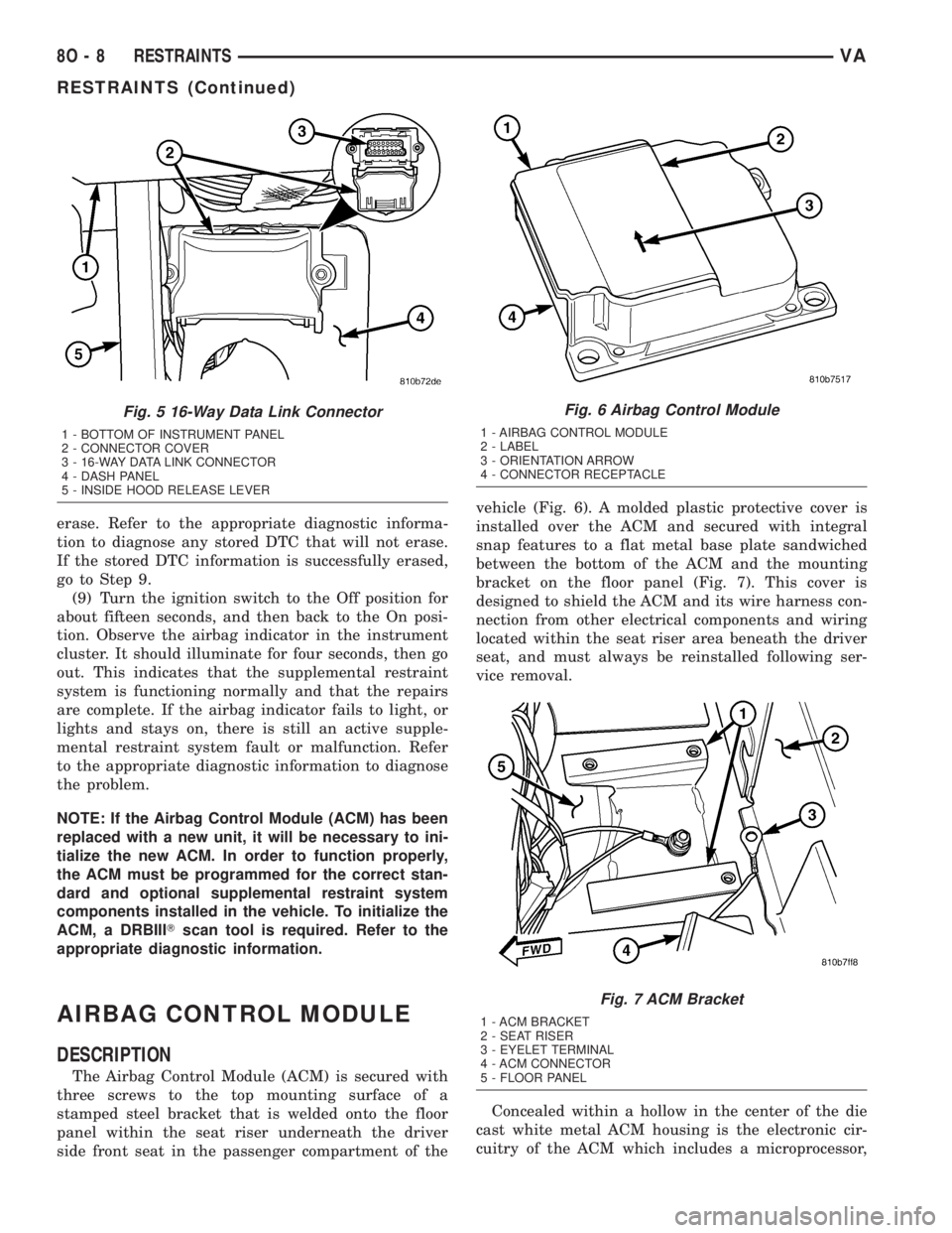
side front seat in the passenger compartment of thevehicle (Fig. 6). A molded plastic protective cover is
installed over the ACM and secured with integral
snap features to a flat metal base plate sandwiched
between the bottom of the ACM and the mounting
bracket on the floor panel (Fig. 7). This cover is
designed to shield the ACM and its wire harness con-
nection from other electrical components and wiring
located within the seat riser area beneath the driver
seat, and must always be reinstalled following ser-
vice removal.
Concealed within a hollow in the center of the die
cast white metal ACM housing is the electronic cir-
cuitry of the ACM which includes a microprocessor,
Fig. 5 16-Way Data Link Connector
1 - BOTTOM OF INSTRUMENT PANEL
2 - CONNECTOR COVER
3 - 16-WAY DATA LINK CONNECTOR
4 - DASH PANEL
5 - INSIDE HOOD RELEASE LEVER
Fig. 6 Airbag Control Module
1 - AIRBAG CONTROL MODULE
2 - LABEL
3 - ORIENTATION ARROW
4 - CONNECTOR RECEPTACLE
Fig. 7 ACM Bracket
1 - ACM BRACKET
2 - SEAT RISER
3 - EYELET TERMINAL
4 - ACM CONNECTOR
5 - FLOOR PANEL
8O - 8 RESTRAINTSVA
RESTRAINTS (Continued)
Page 319 of 1232
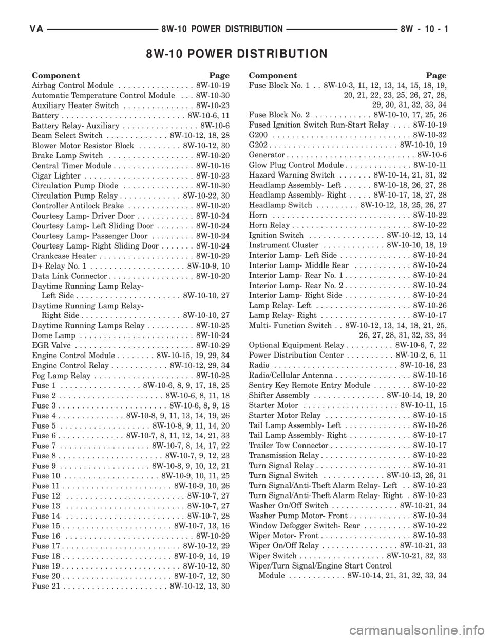
8W-10 POWER DISTRIBUTION
Component Page
Airbag Control Module................ 8W-10-19
Automatic Temperature Control Module . . . 8W-10-30
Auxiliary Heater Switch............... 8W-10-23
Battery.......................... 8W-10-6, 11
Battery Relay- Auxiliary................ 8W-10-6
Beam Select Switch............. 8W-10-12, 18, 28
Blower Motor Resistor Block......... 8W-10-12, 30
Brake Lamp Switch.................. 8W-10-20
Central Timer Module................. 8W-10-16
Cigar Lighter....................... 8W-10-23
Circulation Pump Diode............... 8W-10-30
Circulation Pump Relay............. 8W-10-22, 30
Controller Antilock Brake.............. 8W-10-20
Courtesy Lamp- Driver Door............ 8W-10-24
Courtesy Lamp- Left Sliding Door........ 8W-10-24
Courtesy Lamp- Passenger Door......... 8W-10-24
Courtesy Lamp- Right Sliding Door....... 8W-10-24
Crankcase Heater.................... 8W-10-29
D+ Relay No. 1.................... 8W-10-9, 10
Data Link Connector.................. 8W-10-20
Daytime Running Lamp Relay-
Left Side...................... 8W-10-10, 27
Daytime Running Lamp Relay-
Right Side..................... 8W-10-10, 27
Daytime Running Lamps Relay.......... 8W-10-25
Dome Lamp........................ 8W-10-24
EGR Valve......................... 8W-10-29
Engine Control Module........ 8W-10-15, 19, 29, 34
Engine Control Relay............ 8W-10-12, 29, 34
Fog Lamp Relay..................... 8W-10-28
Fuse 1................. 8W-10-6, 8, 9, 17, 18, 25
Fuse 2...................... 8W-10-6, 8, 11, 18
Fuse 3....................... 8W-10-6, 8, 9, 18
Fuse 4.............. 8W-10-8, 9, 11, 13, 14, 19, 26
Fuse 5................... 8W-10-8, 9, 11, 14, 20
Fuse 6.............. 8W-10-7, 8, 11, 12, 14, 21, 33
Fuse 7................... 8W-10-7, 8, 14, 17, 22
Fuse 8...................... 8W-10-7, 9, 12, 23
Fuse 9................... 8W-10-8, 9, 10, 12, 21
Fuse 10.................... 8W-10-9, 10, 11, 25
Fuse 11....................... 8W-10-9, 10, 26
Fuse 12......................... 8W-10-7, 27
Fuse 13......................... 8W-10-7, 27
Fuse 14......................... 8W-10-7, 28
Fuse 15....................... 8W-10-7, 13, 16
Fuse 16........................... 8W-10-29
Fuse 17......................... 8W-10-12, 29
Fuse 18....................... 8W-10-9, 14, 19
Fuse 19......................... 8W-10-12, 30
Fuse 20....................... 8W-10-7, 12, 30
Fuse 21...................... 8W-10-12, 13, 30
Component Page
Fuse Block No. 1 . . 8W-10-3, 11, 12, 13, 14, 15, 18, 19,
20, 21, 22, 23, 25, 26, 27, 28,
29, 30, 31, 32, 33, 34
Fuse Block No. 2............ 8W-10-10, 17, 25, 26
Fused Ignition Switch Run-Start Relay.... 8W-10-19
G200............................. 8W-10-32
G202........................... 8W-10-10, 19
Generator........................... 8W-10-6
Glow Plug Control Module.............. 8W-10-11
Hazard Warning Switch....... 8W-10-14, 21, 31, 32
Headlamp Assembly- Left...... 8W-10-18, 26, 27, 28
Headlamp Assembly- Right..... 8W-10-17, 18, 27, 28
Headlamp Switch......... 8W-10-12, 18, 25, 26, 27
Horn............................. 8W-10-22
Horn Relay......................... 8W-10-22
Ignition Switch................ 8W-10-12, 13, 14
Instrument Cluster............. 8W-10-10, 18, 19
Interior Lamp- Left Side............... 8W-10-24
Interior Lamp- Middle Rear............ 8W-10-24
Interior Lamp- Rear No. 1.............. 8W-10-24
Interior Lamp- Rear No. 2.............. 8W-10-24
Interior Lamp- Right Side.............. 8W-10-24
Lamp Relay- Left.................... 8W-10-26
Lamp Relay- Right................... 8W-10-17
Multi- Function Switch . . 8W-10-12, 13, 14, 18, 21, 25,
26, 27, 28, 31, 32, 33, 34
Optional Equipment Relay.......... 8W-10-6, 7, 22
Power Distribution Center.......... 8W-10-2, 6, 11
Radio.......................... 8W-10-16, 23
Radio/Cellular Antenna................ 8W-10-16
Sentry Key Remote Entry Module........ 8W-10-22
Shifter Assembly............... 8W-10-14, 19, 20
Starter Motor.................... 8W-10-11, 15
Starter Motor Relay.................. 8W-10-15
Tail Lamp Assembly- Left.............. 8W-10-26
Tail Lamp Assembly- Right............. 8W-10-17
Trailer Tow Connector................. 8W-10-17
Transmission Relay................... 8W-10-22
Turn Signal Relay.................... 8W-10-31
Turn Signal Switch............. 8W-10-13, 26, 31
Turn Signal/Anti-Theft Alarm Relay- Left . . 8W-10-23
Turn Signal/Anti-Theft Alarm Relay- Right . 8W-10-23
Washer On/Off Switch.............. 8W-10-21, 34
Washer Pump Motor- Front............. 8W-10-34
Window Defogger Switch- Rear.......... 8W-10-22
Wiper Motor- Front................... 8W-10-33
Wiper On/Off Relay................ 8W-10-21, 33
Wiper Switch.................. 8W-10-21, 32, 33
Wiper/Turn Signal/Engine Start Control
Module............ 8W-10-14, 21, 31, 32, 33, 34
VA8W-10 POWER DISTRIBUTION 8W - 10 - 1
Page 393 of 1232
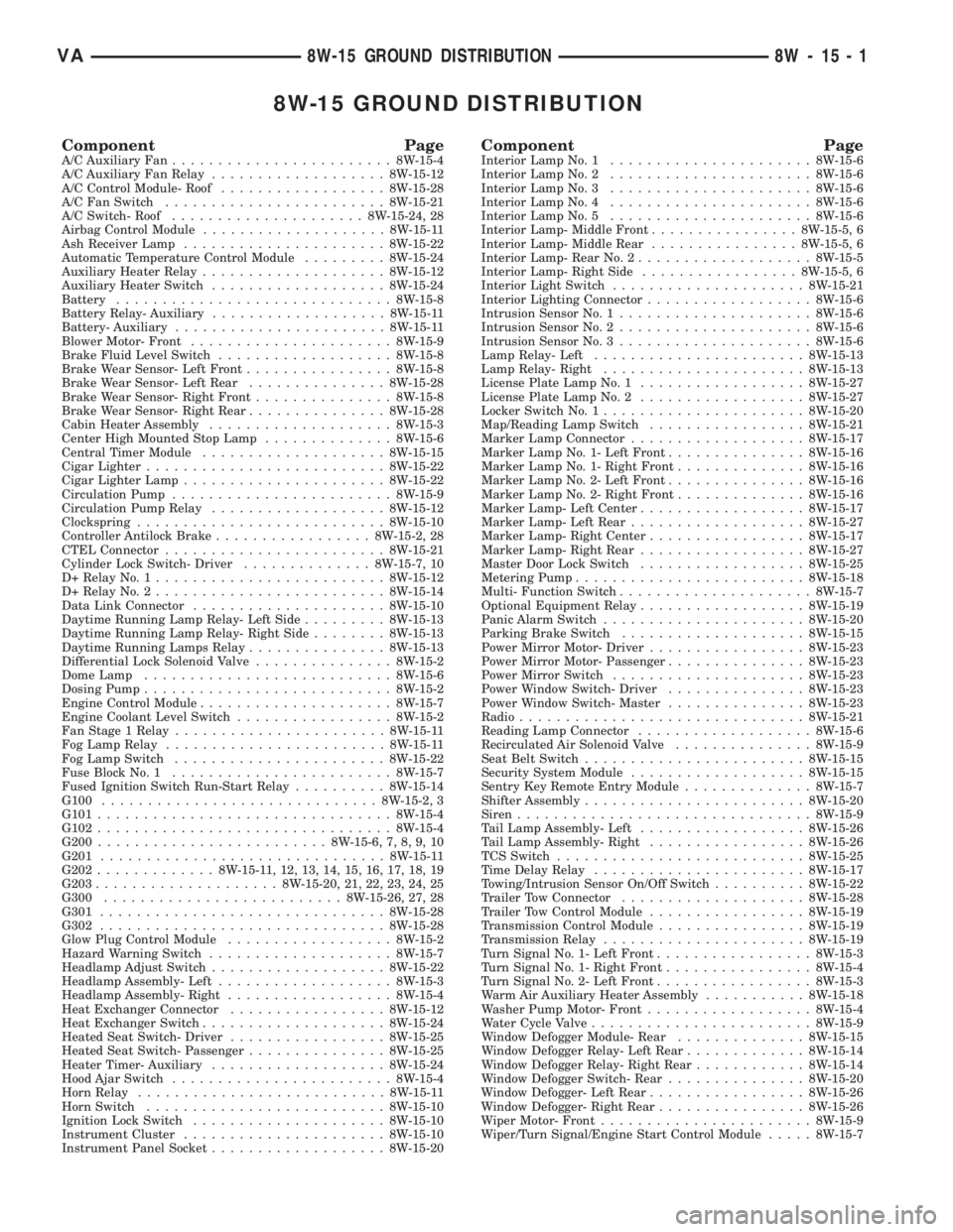
8W-15 GROUND DISTRIBUTION
Component PageA/C Auxiliary Fan........................8W-15-4
A/C Auxiliary Fan Relay...................8W-15-12
A/C Control Module- Roof..................8W-15-28
A/C Fan Switch........................8W-15-21
A/C Switch- Roof.....................8W-15-24, 28
Airbag Control Module....................8W-15-11
Ash Receiver Lamp......................8W-15-22
Automatic Temperature Control Module.........8W-15-24
Auxiliary Heater Relay....................8W-15-12
Auxiliary Heater Switch...................8W-15-24
Battery..............................8W-15-8
Battery Relay- Auxiliary...................8W-15-11
Battery- Auxiliary.......................8W-15-11
Blower Motor- Front......................8W-15-9
Brake Fluid Level Switch...................8W-15-8
Brake Wear Sensor- Left Front................8W-15-8
Brake Wear Sensor- Left Rear...............8W-15-28
Brake Wear Sensor- Right Front...............8W-15-8
Brake Wear Sensor- Right Rear...............8W-15-28
Cabin Heater Assembly....................8W-15-3
Center High Mounted Stop Lamp..............8W-15-6
Central Timer Module....................8W-15-15
Cigar Lighter..........................8W-15-22
Cigar Lighter Lamp......................8W-15-22
Circulation Pump........................8W-15-9
Circulation Pump Relay...................8W-15-12
Clockspring...........................8W-15-10
Controller Antilock Brake.................8W-15-2, 28
CTEL Connector........................8W-15-21
Cylinder Lock Switch- Driver..............8W-15-7, 10
D+ Relay No. 1.........................8W-15-12
D+ Relay No. 2.........................8W-15-14
Data Link Connector.....................8W-15-10
Daytime Running Lamp Relay- Left Side.........8W-15-13
Daytime Running Lamp Relay- Right Side........8W-15-13
Daytime Running Lamps Relay...............8W-15-13
Differential Lock Solenoid Valve...............8W-15-2
Dome Lamp...........................8W-15-6
Dosing Pump...........................8W-15-2
Engine Control Module.....................8W-15-7
Engine Coolant Level Switch.................8W-15-2
Fan Stage 1 Relay.......................8W-15-11
Fog Lamp Relay........................8W-15-11
Fog Lamp Switch.......................8W-15-22
Fuse Block No. 1........................8W-15-7
Fused Ignition Switch Run-Start Relay..........8W-15-14
G100..............................8W-15-2, 3
G101................................8W-15-4
G102................................8W-15-4
G200.........................8W-15-6, 7, 8, 9, 10
G201...............................8W-15-11
G202.............8W-15-11, 12, 13, 14, 15, 16, 17, 18, 19
G203....................8W-15-20, 21, 22, 23, 24, 25
G300..........................8W-15-26, 27, 28
G301...............................8W-15-28
G302...............................8W-15-28
Glow Plug Control Module..................8W-15-2
Hazard Warning Switch....................8W-15-7
Headlamp Adjust Switch...................8W-15-22
Headlamp Assembly- Left...................8W-15-3
Headlamp Assembly- Right..................8W-15-4
Heat Exchanger Connector.................8W-15-12
Heat Exchanger Switch....................8W-15-24
Heated Seat Switch- Driver.................8W-15-25
Heated Seat Switch- Passenger...............8W-15-25
Heater Timer- Auxiliary...................8W-15-24
Hood Ajar Switch........................8W-15-4
Horn Relay...........................8W-15-11
Horn Switch..........................8W-15-10
Ignition Lock Switch.....................8W-15-10
Instrument Cluster......................8W-15-10
Instrument Panel Socket...................8W-15-20Component PageInterior Lamp No. 1......................8W-15-6
Interior Lamp No. 2......................8W-15-6
Interior Lamp No. 3......................8W-15-6
Interior Lamp No. 4......................8W-15-6
Interior Lamp No. 5......................8W-15-6
Interior Lamp- Middle Front................8W-15-5, 6
Interior Lamp- Middle Rear................8W-15-5, 6
Interior Lamp- Rear No. 2...................8W-15-5
Interior Lamp- Right Side.................8W-15-5, 6
Interior Light Switch.....................8W-15-21
Interior Lighting Connector..................8W-15-6
Intrusion Sensor No. 1.....................8W-15-6
Intrusion Sensor No. 2.....................8W-15-6
Intrusion Sensor No. 3.....................8W-15-6
Lamp Relay- Left.......................8W-15-13
Lamp Relay- Right......................8W-15-13
License Plate Lamp No. 1..................8W-15-27
License Plate Lamp No. 2..................8W-15-27
Locker Switch No. 1......................8W-15-20
Map/Reading Lamp Switch.................8W-15-21
Marker Lamp Connector...................8W-15-17
Marker Lamp No. 1- Left Front...............8W-15-16
Marker Lamp No. 1- Right Front..............8W-15-16
Marker Lamp No. 2- Left Front...............8W-15-16
Marker Lamp No. 2- Right Front..............8W-15-16
Marker Lamp- Left Center..................8W-15-17
Marker Lamp- Left Rear...................8W-15-27
Marker Lamp- Right Center.................8W-15-17
Marker Lamp- Right Rear..................8W-15-27
Master Door Lock Switch..................8W-15-25
Metering Pump.........................8W-15-18
Multi- Function Switch.....................8W-15-7
Optional Equipment Relay..................8W-15-19
Panic Alarm Switch......................8W-15-20
Parking Brake Switch....................8W-15-15
Power Mirror Motor- Driver.................8W-15-23
Power Mirror Motor- Passenger...............8W-15-23
Power Mirror Switch.....................8W-15-23
Power Window Switch- Driver...............8W-15-23
Power Window Switch- Master...............8W-15-23
Radio...............................8W-15-21
Reading Lamp Connector...................8W-15-6
Recirculated Air Solenoid Valve...............8W-15-9
Seat Belt Switch........................8W-15-15
Security System Module...................8W-15-15
Sentry Key Remote Entry Module..............8W-15-7
Shifter Assembly........................8W-15-20
Siren................................8W-15-9
Tail Lamp Assembly- Left..................8W-15-26
Tail Lamp Assembly- Right.................8W-15-26
TCS Switch...........................8W-15-25
Time Delay Relay.......................8W-15-17
Towing/Intrusion Sensor On/Off Switch..........8W-15-22
Trailer Tow Connector....................8W-15-28
Trailer Tow Control Module.................8W-15-19
Transmission Control Module................8W-15-19
Transmission Relay......................8W-15-19
Turn Signal No. 1- Left Front.................8W-15-3
Turn Signal No. 1- Right Front................8W-15-4
Turn Signal No. 2- Left Front.................8W-15-3
Warm Air Auxiliary Heater Assembly...........8W-15-18
Washer Pump Motor- Front..................8W-15-4
Water Cycle Valve........................8W-15-9
Window Defogger Module- Rear..............8W-15-15
Window Defogger Relay- Left Rear.............8W-15-14
Window Defogger Relay- Right Rear............8W-15-14
Window Defogger Switch- Rear...............8W-15-20
Window Defogger- Left Rear.................8W-15-26
Window Defogger- Right Rear................8W-15-26
Wiper Motor- Front.......................8W-15-9
Wiper/Turn Signal/Engine Start Control Module.....8W-15-7
VA8W-15 GROUND DISTRIBUTION 8W - 15 - 1
Page 865 of 1232
COLUMN
TABLE OF CONTENTS
page page
COLUMN
SPECIFICATIONS - TORQUE CHART.........5
INTERMEDIATE SHAFT
REMOVAL.............................5
INSTALLATION..........................5
KEY/LOCK CYLINDER
REMOVAL.............................6INSTALLATION..........................7
STEERING WHEEL
REMOVAL.............................7
INSTALLATION..........................7
COLUMN
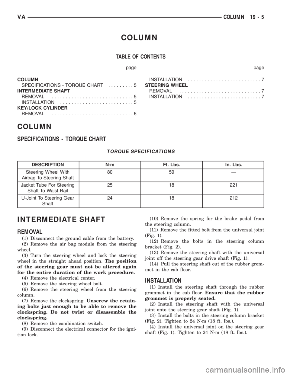
SPECIFICATIONS - TORQUE CHART
TORQUE SPECIFICATIONS
DESCRIPTION N´m Ft. Lbs. In. Lbs.
Steering Wheel With
Airbag To Steering Shaft80 59 Ð
Jacket Tube For Steering
Shaft To Waist Rail25 18 221
U-Joint To Steering Gear
Shaft24 18 212
INTERMEDIATE SHAFT
REMOVAL
(1) Disconnect the ground cable from the battery.
(2) Remove the air bag module from the steering
wheel.
(3) Turn the steering wheel and lock the steering
wheel in the straight ahead position.The position
of the steering gear must not be altered again
for the entire duration of the work procedure.
(4) Remove the electrical center.
(5) Remove the steering wheel bolt.
(6) Remove the steering wheel from the steering
column.
(7) Remove the clockspring.Unscrew the retain-
ing bolts just enough to be able to remove the
clockspring. Do not twist or disassemble the
clockspring.
(8) Remove the combination switch.
(9) Disconnect the electrical connector for the igni-
tion lock.(10) Remove the spring for the brake pedal from
the steering column.
(11) Remove the fitted bolt from the universal joint
(Fig. 1).
(12) Remove the bolts in the steering column
bracket (Fig. 2).
(13) Remove the steering shaft with the universal
joint off the steering gear drive shaft (Fig. 1).
(14) Pull the steering shaft out of the rubber grom-
met in the cab floor.
INSTALLATION
(1) Install the steering shaft through the rubber
grommet in the cab floor.Ensure that the rubber
grommet is properly seated.
(2) Install the steering shaft with the universal
joint onto the steering gear shaft (Fig. 1).
(3) Install the bolts in the steering column bracket
(Fig. 2). Tighten to 24 N´m (18 ft. lbs.).
(4) Install the universal joint on the steering gear
shaft (Fig. 1). Tighten to 24 N´m (18 ft. lbs.).
VACOLUMN 19 - 5
Page 1151 of 1232
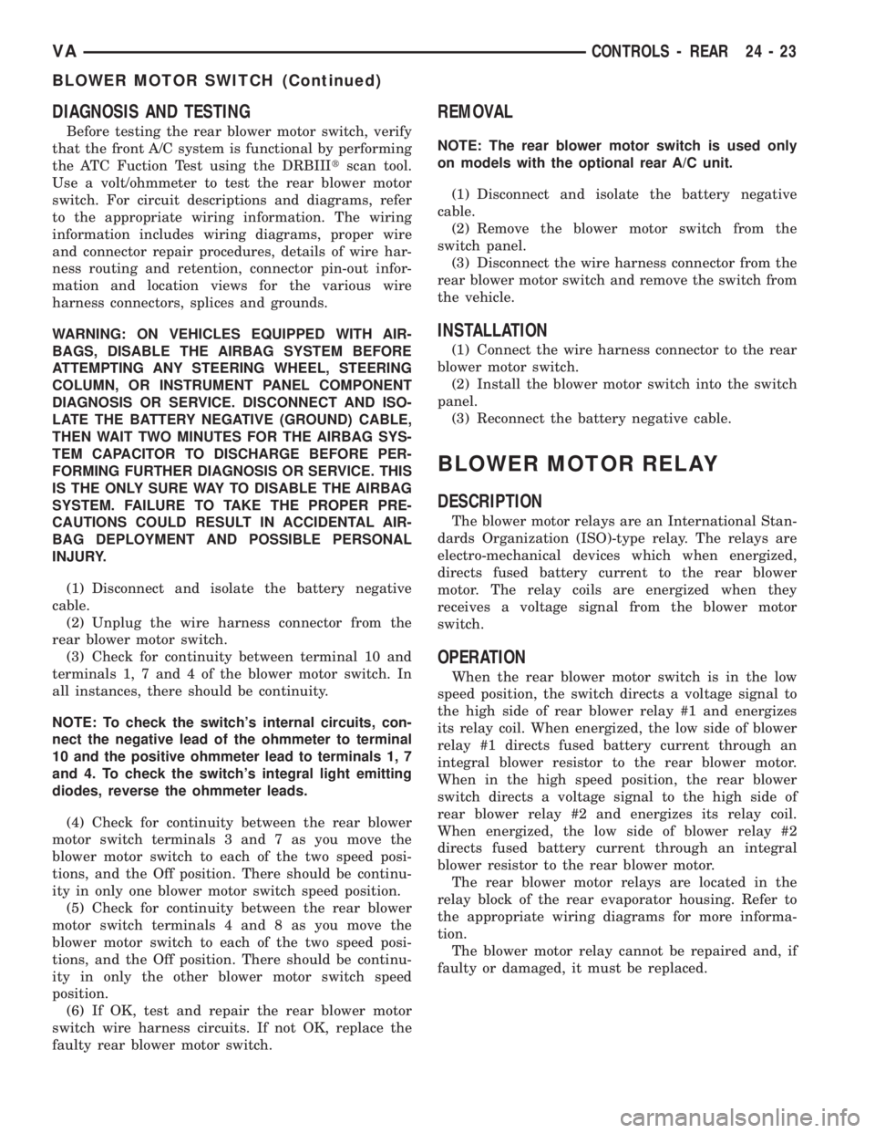
DIAGNOSIS AND TESTING
Before testing the rear blower motor switch, verify
that the front A/C system is functional by performing
the ATC Fuction Test using the DRBIIItscan tool.
Use a volt/ohmmeter to test the rear blower motor
switch. For circuit descriptions and diagrams, refer
to the appropriate wiring information. The wiring
information includes wiring diagrams, proper wire
and connector repair procedures, details of wire har-
ness routing and retention, connector pin-out infor-
mation and location views for the various wire
harness connectors, splices and grounds.
WARNING: ON VEHICLES EQUIPPED WITH AIR-
BAGS, DISABLE THE AIRBAG SYSTEM BEFORE
ATTEMPTING ANY STEERING WHEEL, STEERING
COLUMN, OR INSTRUMENT PANEL COMPONENT
DIAGNOSIS OR SERVICE. DISCONNECT AND ISO-
LATE THE BATTERY NEGATIVE (GROUND) CABLE,
THEN WAIT TWO MINUTES FOR THE AIRBAG SYS-
TEM CAPACITOR TO DISCHARGE BEFORE PER-
FORMING FURTHER DIAGNOSIS OR SERVICE. THIS
IS THE ONLY SURE WAY TO DISABLE THE AIRBAG
SYSTEM. FAILURE TO TAKE THE PROPER PRE-
CAUTIONS COULD RESULT IN ACCIDENTAL AIR-
BAG DEPLOYMENT AND POSSIBLE PERSONAL
INJURY.
(1) Disconnect and isolate the battery negative
cable.
(2) Unplug the wire harness connector from the
rear blower motor switch.
(3) Check for continuity between terminal 10 and
terminals 1, 7 and 4 of the blower motor switch. In
all instances, there should be continuity.
NOTE: To check the switch's internal circuits, con-
nect the negative lead of the ohmmeter to terminal
10 and the positive ohmmeter lead to terminals 1, 7
and 4. To check the switch's integral light emitting
diodes, reverse the ohmmeter leads.
(4) Check for continuity between the rear blower
motor switch terminals 3 and 7 as you move the
blower motor switch to each of the two speed posi-
tions, and the Off position. There should be continu-
ity in only one blower motor switch speed position.
(5) Check for continuity between the rear blower
motor switch terminals 4 and 8 as you move the
blower motor switch to each of the two speed posi-
tions, and the Off position. There should be continu-
ity in only the other blower motor switch speed
position.
(6) If OK, test and repair the rear blower motor
switch wire harness circuits. If not OK, replace the
faulty rear blower motor switch.
REMOVAL
NOTE: The rear blower motor switch is used only
on models with the optional rear A/C unit.
(1) Disconnect and isolate the battery negative
cable.
(2) Remove the blower motor switch from the
switch panel.
(3) Disconnect the wire harness connector from the
rear blower motor switch and remove the switch from
the vehicle.
INSTALLATION
(1) Connect the wire harness connector to the rear
blower motor switch.
(2) Install the blower motor switch into the switch
panel.
(3) Reconnect the battery negative cable.
BLOWER MOTOR RELAY
DESCRIPTION
The blower motor relays are an International Stan-
dards Organization (ISO)-type relay. The relays are
electro-mechanical devices which when energized,
directs fused battery current to the rear blower
motor. The relay coils are energized when they
receives a voltage signal from the blower motor
switch.
OPERATION
When the rear blower motor switch is in the low
speed position, the switch directs a voltage signal to
the high side of rear blower relay #1 and energizes
its relay coil. When energized, the low side of blower
relay #1 directs fused battery current through an
integral blower resistor to the rear blower motor.
When in the high speed position, the rear blower
switch directs a voltage signal to the high side of
rear blower relay #2 and energizes its relay coil.
When energized, the low side of blower relay #2
directs fused battery current through an integral
blower resistor to the rear blower motor.
The rear blower motor relays are located in the
relay block of the rear evaporator housing. Refer to
the appropriate wiring diagrams for more informa-
tion.
The blower motor relay cannot be repaired and, if
faulty or damaged, it must be replaced.
VACONTROLS - REAR 24 - 23
BLOWER MOTOR SWITCH (Continued)