2005 MERCEDES-BENZ SPRINTER ambient temperature indicator
[x] Cancel search: ambient temperature indicatorPage 171 of 1232
INSTRUMENT CLUSTER
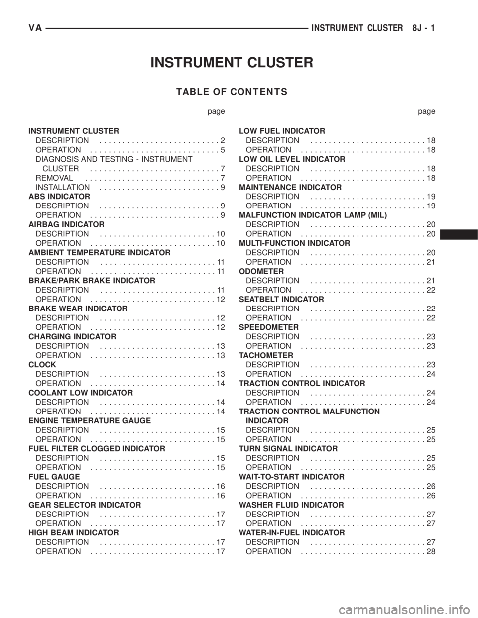
TABLE OF CONTENTS
page page
INSTRUMENT CLUSTER
DESCRIPTION..........................2
OPERATION............................5
DIAGNOSIS AND TESTING - INSTRUMENT
CLUSTER............................7
REMOVAL.............................7
INSTALLATION..........................9
ABS INDICATOR
DESCRIPTION..........................9
OPERATION............................9
AIRBAG INDICATOR
DESCRIPTION.........................10
OPERATION...........................10
AMBIENT TEMPERATURE INDICATOR
DESCRIPTION.........................11
OPERATION...........................11
BRAKE/PARK BRAKE INDICATOR
DESCRIPTION.........................11
OPERATION...........................12
BRAKE WEAR INDICATOR
DESCRIPTION.........................12
OPERATION...........................12
CHARGING INDICATOR
DESCRIPTION.........................13
OPERATION...........................13
CLOCK
DESCRIPTION.........................13
OPERATION...........................14
COOLANT LOW INDICATOR
DESCRIPTION.........................14
OPERATION...........................14
ENGINE TEMPERATURE GAUGE
DESCRIPTION.........................15
OPERATION...........................15
FUEL FILTER CLOGGED INDICATOR
DESCRIPTION.........................15
OPERATION...........................15
FUEL GAUGE
DESCRIPTION.........................16
OPERATION...........................16
GEAR SELECTOR INDICATOR
DESCRIPTION.........................17
OPERATION...........................17
HIGH BEAM INDICATOR
DESCRIPTION.........................17
OPERATION...........................17LOW FUEL INDICATOR
DESCRIPTION.........................18
OPERATION...........................18
LOW OIL LEVEL INDICATOR
DESCRIPTION.........................18
OPERATION...........................18
MAINTENANCE INDICATOR
DESCRIPTION.........................19
OPERATION...........................19
MALFUNCTION INDICATOR LAMP (MIL)
DESCRIPTION.........................20
OPERATION...........................20
MULTI-FUNCTION INDICATOR
DESCRIPTION.........................20
OPERATION...........................21
ODOMETER
DESCRIPTION.........................21
OPERATION...........................22
SEATBELT INDICATOR
DESCRIPTION.........................22
OPERATION...........................22
SPEEDOMETER
DESCRIPTION.........................23
OPERATION...........................23
TACHOMETER
DESCRIPTION.........................23
OPERATION...........................24
TRACTION CONTROL INDICATOR
DESCRIPTION.........................24
OPERATION...........................24
TRACTION CONTROL MALFUNCTION
INDICATOR
DESCRIPTION.........................25
OPERATION...........................25
TURN SIGNAL INDICATOR
DESCRIPTION.........................25
OPERATION...........................25
WAIT-TO-START INDICATOR
DESCRIPTION.........................26
OPERATION...........................26
WASHER FLUID INDICATOR
DESCRIPTION.........................27
OPERATION...........................27
WATER-IN-FUEL INDICATOR
DESCRIPTION.........................27
OPERATION...........................28
VAINSTRUMENT CLUSTER 8J - 1
Page 172 of 1232
INSTRUMENT CLUSTER
DESCRIPTION
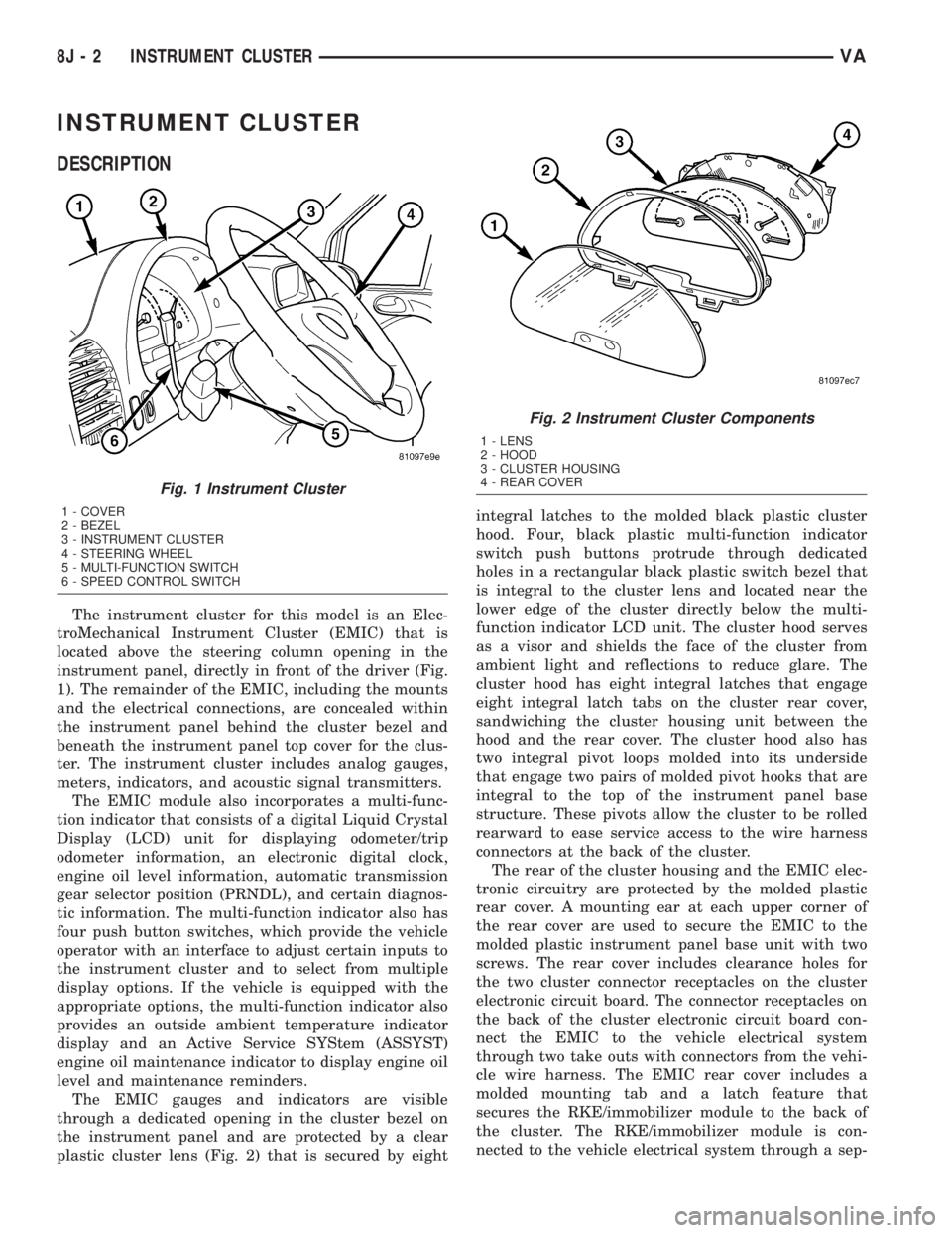
The instrument cluster for this model is an Elec-
troMechanical Instrument Cluster (EMIC) that is
located above the steering column opening in the
instrument panel, directly in front of the driver (Fig.
1). The remainder of the EMIC, including the mounts
and the electrical connections, are concealed within
the instrument panel behind the cluster bezel and
beneath the instrument panel top cover for the clus-
ter. The instrument cluster includes analog gauges,
meters, indicators, and acoustic signal transmitters.
The EMIC module also incorporates a multi-func-
tion indicator that consists of a digital Liquid Crystal
Display (LCD) unit for displaying odometer/trip
odometer information, an electronic digital clock,
engine oil level information, automatic transmission
gear selector position (PRNDL), and certain diagnos-
tic information. The multi-function indicator also has
four push button switches, which provide the vehicle
operator with an interface to adjust certain inputs to
the instrument cluster and to select from multiple
display options. If the vehicle is equipped with the
appropriate options, the multi-function indicator also
provides an outside ambient temperature indicator
display and an Active Service SYStem (ASSYST)
engine oil maintenance indicator to display engine oil
level and maintenance reminders.
The EMIC gauges and indicators are visible
through a dedicated opening in the cluster bezel on
the instrument panel and are protected by a clear
plastic cluster lens (Fig. 2) that is secured by eightintegral latches to the molded black plastic cluster
hood. Four, black plastic multi-function indicator
switch push buttons protrude through dedicated
holes in a rectangular black plastic switch bezel that
is integral to the cluster lens and located near the
lower edge of the cluster directly below the multi-
function indicator LCD unit. The cluster hood serves
as a visor and shields the face of the cluster from
ambient light and reflections to reduce glare. The
cluster hood has eight integral latches that engage
eight integral latch tabs on the cluster rear cover,
sandwiching the cluster housing unit between the
hood and the rear cover. The cluster hood also has
two integral pivot loops molded into its underside
that engage two pairs of molded pivot hooks that are
integral to the top of the instrument panel base
structure. These pivots allow the cluster to be rolled
rearward to ease service access to the wire harness
connectors at the back of the cluster.
The rear of the cluster housing and the EMIC elec-
tronic circuitry are protected by the molded plastic
rear cover. A mounting ear at each upper corner of
the rear cover are used to secure the EMIC to the
molded plastic instrument panel base unit with two
screws. The rear cover includes clearance holes for
the two cluster connector receptacles on the cluster
electronic circuit board. The connector receptacles on
the back of the cluster electronic circuit board con-
nect the EMIC to the vehicle electrical system
through two take outs with connectors from the vehi-
cle wire harness. The EMIC rear cover includes a
molded mounting tab and a latch feature that
secures the RKE/immobilizer module to the back of
the cluster. The RKE/immobilizer module is con-
nected to the vehicle electrical system through a sep-
Fig. 1 Instrument Cluster
1 - COVER
2 - BEZEL
3 - INSTRUMENT CLUSTER
4 - STEERING WHEEL
5 - MULTI-FUNCTION SWITCH
6 - SPEED CONTROL SWITCH
Fig. 2 Instrument Cluster Components
1 - LENS
2 - HOOD
3 - CLUSTER HOUSING
4 - REAR COVER
8J - 2 INSTRUMENT CLUSTERVA
Page 174 of 1232
Except for the indications provided within the
multi-function indicator LCD unit, each indicator in
the EMIC is illuminated by a dedicated LED that is
soldered onto the EMIC electronic circuit board.
Cluster illumination is accomplished by dimmable
LED back lighting, which illuminates the gauges for
visibility when the exterior lighting is turned on. The
cluster general illumination LED units are also sol-
dered onto the EMIC electronic circuit board. The
LED units are not available for service replacement
and, if damaged or faulty, the entire EMIC must be
replaced.
Hard wired circuitry connects the EMIC to the
electrical system of the vehicle. These hard wired cir-cuits are integral to the vehicle wire harnesses,
which are routed throughout the vehicle and retained
by many different methods. These circuits may be
connected to each other, to the vehicle electrical sys-
tem and to the EMIC through the use of a combina-
tion of soldered splices, splice block connectors, and
many different types of wire harness terminal con-
nectors and insulators. Refer to the appropriate wir-
ing information. The wiring information includes
wiring diagrams, proper wire and connector repair
procedures, further details on wire harness routing
and retention, as well as pin-out and location views
for the various wire harness connectors, splices and
grounds.
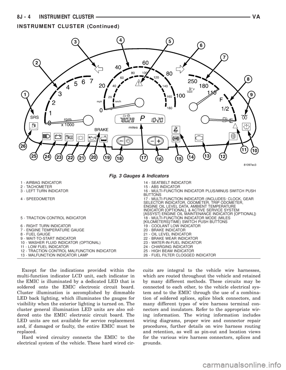
Fig. 3 Gauges & Indicators
1 - AIRBAG INDICATOR 14 - SEATBELT INDICATOR
2 - TACHOMETER 15 - ABS INDICATOR
3 - LEFT TURN INDICATOR 16 - MULTI-FUNCTION INDICATOR PLUS/MINUS SWITCH PUSH
BUTTONS
4 - SPEEDOMETER 17 - MULTI-FUNCTION INDICATOR (INCLUDES: CLOCK, GEAR
SELECTOR INDICATOR, ODOMETER, TRIP ODOMETER,
ENGINE OIL LEVEL DATA, AMBIENT TEMPERATURE
INDICATOR [OPTIONAL], & ACTIVE SERVICE SYSTEM
[ASSYST] ENGINE OIL MAINTENANCE INDICATOR [OPTIONAL])
5 - TRACTION CONTROL INDICATOR 18 - MULTI-FUNCTION INDICATOR MODE (MILES
[KILOMETERS]/TIME) SWITCH PUSH BUTTONS
6 - RIGHT TURN INDICATOR 19 - COOLANT LOW INDICATOR
7 - ENGINE TEMPERATURE GAUGE 20 - BRAKE INDICATOR
8 - FUEL GAUGE 21 - OIL LEVEL INDICATOR
9 - WAIT-TO-START INDICATOR 22 - BRAKE WEAR INDICATOR
10 - WASHER FLUID INDICATOR (OPTIONAL) 23 - WATER-IN-FUEL INDICATOR
11 - LOW FUEL INDICATOR 24 - CHARGING INDICATOR
12 - TRACTION CONTROL MALFUNCTION INDICATOR 25 - HIGH BEAM INDICATOR
13 - MALFUNCTION INDICATOR LAMP 26 - FUEL FILTER CLOGGED INDICATOR
8J - 4 INSTRUMENT CLUSTERVA
INSTRUMENT CLUSTER (Continued)
Page 176 of 1232
INDICATORS
Indicators are located in various positions within
the EMIC and are all connected to the EMIC elec-
tronic circuit board. The ambient temperature indica-
tor (optional), brake indicator, brake wear indicator,
charging indicator, coolant low indicator, high beam
indicator, low fuel indicator, seatbelt indicator, turn
signal indicators, and washer fluid indicator operate
based upon hard wired inputs to the EMIC. The air-
bag (SRS) indicator is normally controlled by a hard
wired input from the Airbag Control Module (ACM);
however, if the EMIC sees an abnormal or no input
from the ACM, it will automatically turn the airbag
indicator On until the hard wired input from the
ACM has been restored. The Malfunction Indicator
Lamp (MIL) is normally controlled by CAN data bus
messages from the Engine Control Module (ECM);
however, if the EMIC loses CAN data bus communi-
cation, the EMIC circuitry will automatically turn
the MIL on until CAN data bus communication is
restored. The EMIC uses CAN data bus messages
from the ECM, the ACM, and the Controller Antilock
Brake to control all of the remaining indicators.
The various EMIC indicators are controlled by dif-
ferent strategies; some receive battery feed from the
EMIC circuitry and have a switched ground, while
others are grounded through the EMIC circuitry and
have a switched battery feed. However, all indicators
are completely controlled by the EMIC microproces-
sor based upon various hard wired and electronic
message inputs. Except for the indications provided
by the multi-function indicator Liquid Crystal Dis-
play (LCD) unit, all indicators are illuminated at a
fixed intensity, which is not affected by the selected
illumination intensity of the EMIC general illumina-
tion lamps.
The hard wired indicator inputs may be diagnosed
using conventional diagnostic methods. However,
proper testing of the EMIC circuitry and the CAN
bus message controlled indicators requires the use of
a DRBIIItscan tool. Refer to the appropriate diag-
nostic information. Specific details of the operation
for each indicator may be found elsewhere in this
service information.
CLUSTER ILLUMINATION
The EMIC has several general illumination lamps
that are illuminated when the exterior lighting is
turned on with the multi-function switch. The illumi-
nation intensity of these lamps is adjusted by a dim-
ming level input received from the multi-function
indicator ª+º (plus) and ª±º (minus) switch push but-
tons that extend through the lower edge of the clus-
ter lens below the right end of the multi-function
indicator. When the exterior lighting is turned Off,
the display is illuminated at maximum brightness.When the exterior lighting is turned On and the
transmission gear selector is in the Park position,
depressing the plus switch push button brightens the
display lighting, and depressing the minus switch
push button dims the display lighting. The EMIC
also provides a Pulse-Width Modulated (PWM) panel
lamps dimmer output that can be used to synchro-
nize the illumination lighting levels of external illu-
mination lamps (up to about 23 to 30 watts) with
that of the EMIC.
The hard wired multi-function switch input and
the EMIC panel lamps dimmer output may be diag-
nosed using conventional diagnostic methods. How-
ever, proper testing of the PWM control of the EMIC
and the electronic dimming level inputs from the
multi-function indicator push buttons requires the
use of a DRBIIItscan tool. Refer to the appropriate
diagnostic information.
INPUT AND OUTPUT CIRCUITS
HARD WIRED INPUTS
The hard wired inputs to the EMIC include the fol-
lowing:
NOTE: Final approved circuit names were not yet
available at the time this information was compiled.
²Airbag Indicator Driver
²Ambient Temperature Sensor Signal
(Optional)
²Brake Wear Indicator Sense
²Charging Indicator Driver
²Coolant Level Switch Sense
²Front Door Jamb Switch Sense
²Fuel Level Sensor Signal
²Fused B(+)
²Fused Ignition Switch Output
²High Beam Indicator Driver
²Key-In Ignition Switch Sense
²Left Turn Signal
²Park Brake Switch Sense
²Right Turn Signal
²Seat Belt Switch Sense
²Washer Fluid Switch Sense (Optional)
Refer to the appropriate wiring information for
additional details.
HARD WIRED OUTPUTS
The hard wired outputs of the EMIC include the
following:
NOTE: Final approved circuit names were not yet
available at the time this information was compiled.
²Engine Running Relay Control
²Panel Lamps Driver
8J - 6 INSTRUMENT CLUSTERVA
INSTRUMENT CLUSTER (Continued)
Page 181 of 1232
AMBIENT TEMPERATURE
INDICATOR
DESCRIPTION
An ambient temperature indicator is optional
equipment on all instrument clusters. In vehicles so
equipped, the ambient temperature indication can be
toggled with the clock indication on the right side of
the multi-function indicator Liquid Crystal Display
(LCD) located near the lower edge of the instrument
cluster, directly below the speedometer. The ambient
temperature indication consists of a numeric value
with a ª+º (plus) or ª2º (minus) prefix, and the unit
of measure is identified with the characters ªÉCº
(Canadian vehicles only) or ªÉFº (United States vehi-
cles only) located directly above the temperature
indication. The indications of the ambient tempera-
ture indicator are not visible when the LCD is not
illuminated. When illuminated the indications
appear as dark characters and icons silhouetted
against an amber field. When the exterior lighting is
turned Off, the display is illuminated at maximum
brightness. When the exterior lighting is turned On
the display illumination level can be adjusted in con-
cert with the cluster general illumination lighting
using the ª+º (plus) and ª2º (minus) multi-function
indicator push buttons. The ambient temperature
indicator is serviced as a unit with the instrument
cluster.
OPERATION
The optional ambient temperature indicator gives
an indication to the vehicle operator of the outside
air temperature. This indicator is controlled by the
instrument cluster microprocessor based upon cluster
programming and a hard wired input received by the
cluster from the ambient temperature sensor. The
ambient temperature indicator is completely con-
trolled by the instrument cluster logic circuit, and
that logic will allow this indicator to operate when-
ever the multi-function indicator Liquid Crystal Dis-
play (LCD) is activated. Therefore, the ambient
temperature indicator remains functional regardless
of the ignition switch position.
The vehicle operator can choose to have the ambi-
ent temperature indicator displayed instead of the
clock information, but the clock and ambient temper-
ature indicator cannot be displayed at the same time.
The clock or ambient temperature indicator display
option is selected using the multi-function indicator
clock switch on the instrument cluster circuit board.
This switch is actuated manually by depressing the
clock switch push button that extends through the
lower edge of the cluster lens below the left end of
the multi-function indicator. Actuating this switchmomentarily will toggle the display between the
clock and ambient temperature indicator modes.
Actuating this switch twice within about one second
will cause the display to toggle, but then automati-
cally revert to the originally selected mode after
about twenty seconds.
The ambient temperature sensor located below the
front bumper is a Negative Temperature Coefficient
(NTC) thermistor. The internal resistance of the sen-
sor is reduced as the ambient temperature rises. The
instrument cluster continually monitors the resis-
tance through the sensor to determine the tempera-
ture value to be displayed. The current value is
displayed immediately after the LCD is activated.
The display value will remain static regardless of
decreases in the sensor resistance (temperature ris-
ing) below vehicle speeds of 10 to 15 kilometers-per-
hour (6 to 9 miles-per-hour). Decreases in the sensor
resistance above 15 kilometers-per-hour (9 miles-per-
hour) and increases the sensor resistance (tempera-
ture falling) regardless of vehicle speed are displayed
subject to a sixty second delay.
The ambient temperature sensor is connected to
the instrument cluster in series between the ambient
temperature sensor return and sense circuits. The
ambient temperature sensor and the return and
sense circuits to the instrument cluster can be diag-
nosed using conventional diagnostic tools and meth-
ods. For proper diagnosis of the instrument cluster
circuitry that controls the ambient temperature indi-
cator, a DRBIIItscan tool is required. Refer to the
appropriate diagnostic information.
BRAKE/PARK BRAKE
INDICATOR
DESCRIPTION
A brake indicator is standard equipment on all
instrument clusters. The brake indicator is located
near the lower edge of the instrument cluster, to the
left of the multi-function indicator display. In vehi-
cles built for the United States market, the brake
indicator consists of stencil-like cutout of the word
ªBRAKEº in the opaque layer of the instrument clus-
ter overlay. In vehicles built for the Canadian mar-
ket, the brake indicator consists of the International
Control and Display Symbol icon for ªBrake Failureº
imprinted within a rectangular cutout in the opaque
layer of the instrument cluster overlay. In either
case, the dark outer layer of the overlay prevents the
indicator from being clearly visible when it is not
illuminated. A red Light Emitting Diode (LED)
behind the cutout in the opaque layer of the overlay
causes the ªBRAKEº text to appear in red, or the
icon to appear silhouetted against a red field through
VAINSTRUMENT CLUSTER 8J - 11
Page 183 of 1232
illuminated by the instrument cluster for about two
seconds as a bulb test.
²Brake Wear Sensor Input- Each time the
cluster detects ground on the brake wear sense cir-
cuit (brake wear sensor closed = brake lining wear
limit exceeded) while the ignition switch is in the On
position, the brake wear indicator is illuminated. The
indicator remains illuminated until the brake wear
sense input to the cluster is an open circuit (brake
wear sensor open = brake lining wear within limits),
or until the ignition switch is turned to the Off posi-
tion, whichever occurs first.
A brake wear sensor located at each wheel provides
a hard wired ground input to the instrument cluster
circuitry through the brake wear sense circuit when-
ever the brake linings for that wheel have exceeded
their wear limits. The four normally open brake wear
sensors are connected in parallel between ground and
instrument cluster. The brake wear sensors and their
input circuit to the instrument cluster can be diag-
nosed using conventional diagnostic tools and meth-
ods. For proper diagnosis of the instrument cluster
circuitry that controls the brake wear indicator, a
DRBIIItscan tool is required. Refer to the appropri-
ate diagnostic information.
CHARGING INDICATOR
DESCRIPTION
A charging indicator is standard equipment on all
instrument clusters. The charging indicator is located
near the lower edge of the instrument cluster, to the
left of the multi-function indicator display. The
charging indicator consists of the International Con-
trol and Display Symbol icon for ªBattery Charging
Conditionº imprinted within a rectangular cutout in
the opaque layer of the instrument cluster overlay.
The dark outer layer of the overlay prevents the indi-
cator from being clearly visible when it is not illumi-
nated. A red Light Emitting Diode (LED) behind the
cutout in the opaque layer of the overlay causes the
icon to appear silhouetted against a red field through
the translucent outer layer of the overlay when the
indicator is illuminated from behind by the LED,
which is soldered onto the instrument cluster elec-
tronic circuit board. The charging indicator is ser-
viced as a unit with the instrument cluster.
OPERATION
The charging indicator gives an indication to the
vehicle operator when the electrical system voltage is
too low. This indicator is controlled by a transistor on
the instrument cluster circuit board based upon clus-
ter programming and a hard wired input from the
generator. The charging indicator Light EmittingDiode (LED) is completely controlled by the instru-
ment cluster logic circuit, and that logic will only
allow this indicator to operate when the instrument
cluster detects that the ignition switch is in the On
position. Therefore, the LED will always be off when
the ignition switch is in any position except On. The
LED only illuminates when it is provided a path to
ground by the instrument cluster transistor. The
instrument cluster will turn on the charging indica-
tor for the following reasons:
²Bulb Test- Each time the ignition switch is
turned to the On position with the engine not run-
ning the charging indicator is illuminated by the
instrument cluster as a bulb test.
²Generator Input- Each time the cluster
detects that the voltage of the generator input is 12.7
volts or lower while the engine is running, the charg-
ing indicator will be illuminated. The indicator
remains illuminated until the cluster detects that the
voltage of the generator input is above 12.7 volts, or
until the ignition switch is turned to the Off position,
whichever occurs first.
The generator provides a hard wired input to the
instrument cluster circuitry on the engine running
(D+) circuit. If the instrument cluster turns on the
indicator while the engine is running, it may indicate
that the charging system requires service. The gener-
ator input circuit to the instrument cluster can be
diagnosed using conventional diagnostic tools and
methods. For proper diagnosis of the charging sys-
tem, or the instrument cluster circuitry that controls
the charging indicator, a DRBIIItscan tool is
required. Refer to the appropriate diagnostic infor-
mation.
CLOCK
DESCRIPTION
An electronic digital clock is standard equipment
on all instrument clusters. In vehicles equipped with
the optional ambient temperature indicator, the clock
indication can be toggled with the ambient tempera-
ture indication on the right side of the multi-function
indicator Liquid Crystal Display (LCD) located near
the lower edge of the instrument cluster, directly
below the speedometer. The clock provides a 12 hour-
based, digital indication of the current hours and
minutes. The indications of the clock are not visible
when the LCD is not illuminated. When illuminated
the indications appear as dark characters silhouetted
against an amber field. When the exterior lighting is
turned Off, the display is illuminated at maximum
brightness. When the exterior lighting is turned On
the display illumination level can be adjusted in con-
cert with the cluster general illumination lighting
VAINSTRUMENT CLUSTER 8J - 13
BRAKE WEAR INDICATOR (Continued)
Page 184 of 1232
using the ª+º (plus) and ª2º (minus) multi-function
indicator push buttons. The clock is serviced as a
unit with the instrument cluster.
OPERATION
The clock gives an indication to the vehicle opera-
tor of the current time. The electronic digital clock is
controlled by the instrument cluster microprocessor
based upon cluster programming. The clock display is
completely controlled by the instrument cluster logic
circuit, and that logic will only allow this indication
to be viewed when the multi-function indicator Liq-
uid Crystal Display (LCD) is activated. However, the
clock remains functional regardless of the ignition
switch position.
The vehicle operator can choose to have the
optional ambient temperature indicator displayed
instead of the clock information, but the clock and
ambient temperature indicator cannot be displayed
at the same time. The clock or ambient temperature
indicator display option is selected using the multi-
function indicator clock switch on the instrument
cluster circuit board. This switch is actuated manu-
ally by depressing the clock switch push button that
extends through the lower edge of the cluster lens
below the left end of the multi-function indicator.
Actuating this switch momentarily will toggle the
display between the clock and ambient temperature
indicator modes. Actuating this switch twice within
about one second will cause the display to toggle, but
then automatically revert to the originally selected
mode after about twenty seconds.
See the owner's manual in the vehicle glove box for
more information on the features, use, operation and
setting procedures for the clock. For proper testing of
the instrument cluster circuitry that controls the
clock functions, a DRBIIItscan tool is required.
Refer to the appropriate diagnostic information.
COOLANT LOW INDICATOR
DESCRIPTION
A coolant low indicator is standard equipment on
all instrument clusters. The coolant low indicator is
located near the lower edge of the instrument cluster,
to the left of the multi-function indicator display. The
coolant low indicator consists of the International
Control and Display Symbol icon for ªLow Engine
Coolantº imprinted within a rectangular cutout in
the opaque layer of the instrument cluster overlay.
The dark outer layer of the overlay prevents the indi-
cator from being clearly visible when it is not illumi-
nated. A red Light Emitting Diode (LED) behind the
cutout in the opaque layer of the overlay causes the
icon to appear silhouetted against a red field throughthe translucent outer layer of the overlay when the
indicator is illuminated from behind by the LED,
which is soldered onto the instrument cluster elec-
tronic circuit board. The coolant low indicator is ser-
viced as a unit with the instrument cluster.
OPERATION
The coolant low indicator gives an indication to the
vehicle operator when the engine coolant level is low.
This indicator is controlled by a transistor on the
instrument cluster circuit board based upon cluster
programming and a hard wired input received by the
cluster from the engine coolant level switch. The cool-
ant low indicator Light Emitting Diode (LED) is com-
pletely controlled by the instrument cluster logic
circuit, and that logic will only allow this indicator to
operate when the instrument cluster detects that the
ignition switch is in the On position. Therefore, the
LED will always be off when the ignition switch is in
any position except On. The LED only illuminates
when it is provided a path to ground by the instru-
ment cluster transistor. The instrument cluster will
turn on the coolant low indicator for the following
reasons:
²Bulb Test- Each time the ignition switch is
turned to the On position the coolant low indicator is
illuminated for about two seconds as a bulb test.
²Engine Coolant Level Switch Input- Each
time the cluster detects an appropriate input on the
low coolant fluid level sense circuit (engine coolant
level switch resistance low = engine coolant level low)
while the ignition switch is in the On position, the
coolant low indicator will be illuminated. The indica-
tor remains illuminated until the low coolant fluid
level sense input to the cluster changes (engine cool-
ant level switch resistance high = engine coolant
level full), or until the ignition switch is turned to
the Off position, whichever occurs first. The engine
coolant level switch also features a diagnostic resis-
tor connected in parallel between the switch input
and output to provide the cluster with verification
that the low coolant fluid level sense circuit is not
open or shorted.
The engine coolant level switch integral to the cool-
ant bottle provides a hard wired input to the instru-
ment cluster circuitry through the low coolant fluid
level sense circuit. The engine coolant level switch
and the low coolant fluid level sense circuit to the
instrument cluster can be diagnosed using conven-
tional diagnostic tools and methods. For proper diag-
nosis of the instrument cluster circuitry that controls
the coolant low indicator, a DRBIIItscan tool is
required. Refer to the appropriate diagnostic infor-
mation.
8J - 14 INSTRUMENT CLUSTERVA
CLOCK (Continued)
Page 191 of 1232
OPERATION
The multi-function indicator has several display
capabilities including odometer, trip odometer, clock,
engine oil level data, gear selector indicator
(PRNDL), certain diagnostic information and, on
vehicles so equipped, an optional Active Service SYS-
Tem (ASSYST) engine oil maintenance indicator and
an optional outside ambient temperature indicator.
The multi-function indicator is completely controlled
by the instrument cluster logic circuit, and that logic
will allow this indication to be viewed whenever the
multi-function indicator Liquid Crystal Display
(LCD) is activated. Therefore, the indicator remains
functional regardless of the ignition switch position.
With the ignition switch in the Off or Accessory posi-
tions and the key removed from the ignition lock cyl-
inder, the display is activated when the park lamps
are turned On or, for about thirty seconds after any
one of the multi-function indicator switch push but-
tons is depressed. Otherwise, the display unit is
active for about thirty seconds after the key is
inserted into the ignition lock cylinder, and inactive
about thirty seconds after the key is removed from
the ignition lock cylinder.
The multi-function indicator ªmiº (miles) or
ªkmº(kilometers) switch push button is used to con-
trol the odometer/trip odometer display modes. The
multi-function indicator clock switch push button is
used to control the clock/outside temperature display
modes. The multi-function indicator ª+º (plus) and
ª2º (minus) switch push buttons are used to adjust
the cluster general illumination dimming level, the
clock, and other cluster settings. See the owner's
manual in the vehicle glove box for more information
on the features, use, operation and setting proce-
dures for the various standard and optional multi-
function indicator displays.
Proper testing of the multi-function indicator LCD
unit, the CAN data bus and the electronic data bus
message inputs to the instrument cluster that control
some of the multi-function indicator functions
requires the use of a DRBIIItscan tool. Refer to the
appropriate diagnostic information. Additional details
for the odometer/trip odometer, the clock, the gear
selector indicator, the ambient temperature indicator
and the ASSYST warning and reminder functions of
the multi-function indicator may be found elsewhere
in this service information.
ODOMETER
DESCRIPTION
An odometer and trip odometer are standard
equipment in all instrument clusters. The odometer
and trip odometer values are displayed on the leftside of the multi-function indicator Liquid Crystal
Display (LCD). The LCD is soldered onto the cluster
electronic circuit board and is visible through a win-
dow with a clear lens located near the lower edge of
the instrument cluster, directly below the speedome-
ter. However, the odometer and trip odometer infor-
mation are not displayed simultaneously. The ªmiº
(miles) or ªkmº (kilometers) switch on the instrument
cluster circuit board toggles the display between
odometer and trip odometer modes by depressing the
switch push button that extends through the lower
edge of the cluster lens, directly below the multi-
function indicator LCD.
The odometer and trip odometer information is
stored in the instrument cluster memory. This infor-
mation can be increased when the proper inputs are
provided to the instrument cluster, but the informa-
tion cannot be decreased. The odometer can display
values up to 999,999 kilometers (999,999 miles). The
odometer latches at these values, and will not roll
over to zero. The trip odometer can display values up
to 999.9 kilometers (999.9 miles) before it rolls over
to zero. The odometer display does not have a deci-
mal point and will not show values less than a full
unit (kilometer or mile), while the trip odometer dis-
play does have a decimal point and will show tenths
of a unit (kilometer or mile). The unit of measure
(kilometers or miles) for the odometer and trip odom-
eter display is imprinted on the cluster overlay below
the left end of the LCD. The unit of measure for the
instrument cluster odometer/trip odometer is selected
at the time that it is manufactured, and cannot be
changed.
The indications of the odometer/trip odometer are
not visible when the LCD is not illuminated. When
illuminated the indications appear as dark charac-
ters silhouetted against an amber field. When the
exterior lighting is turned Off, the display is illumi-
nated at maximum brightness. When the exterior
lighting is turned On the display illumination level
can be adjusted in concert with the cluster general
illumination lighting using the plus and minus multi-
function indicator push buttons. The odometer has a
ªRental Carº mode, which will activate the multi-
function indicator LCD and illuminate the odometer
information for about thirty seconds after one of the
multi-function indicator push buttons is momentarily
depressed, or after the key is inserted into the igni-
tion switch lock cylinder with the ignition switch in
the Off position.
The odometer/trip odometer and the miles/kilome-
ters switch, and the miles/kilometers switch push
button are serviced as a unit with the instrument
cluster.
VAINSTRUMENT CLUSTER 8J - 21
MULTI-FUNCTION INDICATOR (Continued)