Page 137 of 205

WARNING:Inexper t modifications or additions to the electrical
system could jeopardise safety.
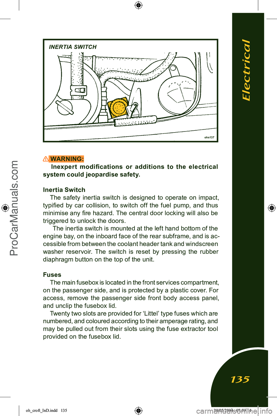
Inertia Switch The safety inertia switch is designed to operate on impact,
typified by car collision, to switch off the fuel pump, and thus
minimise any fire hazard. The central door locking will also be
triggered to unlock the doors. The inertia switch is mounted at the left hand bottom of the
engine bay, on the inboard face of the rear subframe, and is ac
-
cessible from between the coolant header tank and windscreen
washer reservoir. The switch is reset by pressing the rubber
diaphragm button on the top of the unit.
Fuses The main fusebox is located in the front services compartment,
on the passenger side, and is protected by a plastic cover. For
access, remove the passenger side front body access panel,
and unclip the fusebox lid. Twenty two slots are provided for ‘Littel’ type fuses which are
numbered, and coloured according to their amperage rating, and
may be pulled out from their slots using the fuse extractor tool provided on the fusebox lid.
ohs137
INERTIA SWITCH
Electrical
135
oh_croft_InD.indd 13520/05/2004 07:59:14ProCarManuals.com
Page 138 of 205
WARNING:Replacing a fuse with one which has a higher rating may
cause extensive damage to the electrical system and pos
-
sibly cause a fire. If a fuse of the correct rating is not avail
-
able, use one of a lower rating as a temporary measure.
Slot
Rate Circuit Slot Rate Circuit
1 20A Aux pwr socket 12 10A ABS 2 5A Reverse lamps 13 3A ECU Ignition
3 20A Driver’s window 14 20A Rad. fans;
4 20A Pass. window 1&2 slow, 1 fast 5 10A Stoplamps 15 7.5A Radio, switch6 7.5A Turn indicators pack module
7 10A Ignition services 16 10A Parking lamps
8 7.5A Battery services 17 10A Dip beam LH9 15A Hazard lamps 18 10A Dip beam RH
10 7.5A Horn 19 20A A.C. comp. relay,
11 10A Alarm pwr rad fan 2 fast interior lamp 20 15A Main beam LH
21 15A Main beam RH
22 7.5A CDL
m254a
MAIN FUSEBOX
Fuse 1Fuse 11
Fuse 12 Fuse 22
As viewed
from in front
Electrical
136
oh_croft_InD.indd 13620/05/2004 07:59:15ProCarManuals.com
Page 139 of 205
Engine Compartment FusesFuses associated with the engine management system are
contained in two 4-position fuse holders located at the front of
the engine bay on the cabin bulkhead, adjacent to the engine ECM. To access the fuses, unclip rear edge of the cover.
Fuse Rating CircuitR1 20A Fuel pump
R2 3A Immobiliser
R3 5A Alternator sense
R4 5A ECU battery feed
R5 5A O2 heaters
R6 7.5A VSV's V VT, V VL, IAC
R7 10A Injectors, ignition coils
R8 5A Re-circ. pump
WARNING:
• To avoid injury, beware of rotating engine components and guard against entrapment of body parts, tools and
loose clothing.
• Stop engine before servicing fuses.
• Beware of hot surfaces in the engine bay. You could be seriously burned if you touch a hot engine part.
• Take great care not to drop flammable liquids or objects onto a hot engine and start a fire.
ohs136
ENGINE BAY FUSES
4
3
2
1
8
7
6
5
Electrical
137
oh_croft_InD.indd 13720/05/2004 07:59:15ProCarManuals.com
Page 140 of 205
Footwell Sited Fuses Four fuses are secured to the main wiring harness just
ahead of the scuttle beam and accessible from the passenger
footwell.
Fuse Rating CircuitC1 20A Interior fan
C2 15A Wiper motor
C3 7.5A Audio key-in
C4 7.5A A.C. compressor
m248a
Front
Viewed
from
beneath Fusebox ‘C’Electrical
138
oh_croft_InD.indd 13820/05/2004 07:59:15ProCarManuals.com
Page 141 of 205

Headlamp AlignmentThe headlamps of your Elise were correctly adjusted during
the manufacture of the car, and should only require subsequent
adjustment if the headlamp assembly or front body is disturbed.
Simply replacing the bulb will not affect alignment. Incorrectly adjusted headlamps can cause poor lighting performance or dazzle to oncoming traf fic. Special headlamp setting equip
-
ment is required to correctly set the headlamps, such that only
qualified technicians using appropriate equipment should be
entrusted with this procedure:
1. Using beam setting equipment compatible with local regu
-
lations, position the machine between 300 and 700mm in
front of the LH headlamp, and parallel with the two headlamp
units using the sight bar or similar device dependent on the machine design, to ensure cross car match. Use the guides provided on the machine to ensure the correct height and
lateral setting.
2. Switch on the headlamp low beams (uppermost lamps) and check the lateral beam alignment. The ‘knee point’ of the beam cut off line must lie within a tolerance of 2% to the pas
-
senger side, and 0%. Check the vertical alignment of the low beam which must lie within a tolerance of - 0.5% and -2%.
Electrical
139
oh_croft_InD.indd 13920/05/2004 07:59:15ProCarManuals.com
Page 142 of 205

3. If adjustment is required, the clear cover and mask must be removed from the body. From within the wheelarch, remove
the access panel from the wheelarch liner to expose the
headlamp cover retaining screws. Use the hexagonal key provided in the toolkit (in the rear pocket on the batter y
cover) to release the three socket head retaining screws and washers, and withdraw the cover assembly complete
with rubber edge seal from the body. When refitting, do not overtighten the fixings.
4. To adjust the low beam laterally, adjust the dome headed screw at the upper inboard side of the low beam (uppermost)
lamp, accessed from the front of the lamp. Turn clockwise to
adjust the beam to the right. Optimum setting is 0%. To adjust
the vertical aim of the low beam, adjust the dome headed screw at the lower outboard side of the lamp, accessed
from the front of the lamp. Turn clockwise to raise the beam.
Optimum setting is -1.5%.
5. Repeat for the RH lamp. 6. Centralise the machine on the LH high beam (lowermost) lamp, and switch on the high beams. Check the high beam
alignment which should be centralised with the marker dot on
the machine screen or slightly below the horizontal. Optimum
setting is 0%.
ohs105a
HEADLAMP COVER UNIT SOCKET BOLTS
Electrical
140
oh_croft_InD.indd 14020/05/2004 07:59:16ProCarManuals.com
Page 143 of 205
- To adjust the high beam laterally, adjust the dome headed screw at the upper inboard side of the lamp, accessed from behind the lamp. Turn clockwise to adjust the beam to the
right.
- To adjust the vertical aim of the high beam, adjust the dome headed screw at the lower outboard side of the lamp, ac
-
cessed from behind the lamp. Turn clockwise to raise the
beam.
7. Repeat for the RH lamp. 8. Re-fit the cover/mask assemblies complete with edge seal to the body, and secure with the three socket head screws and
washers. Refit the wheelarch access panel.
m257
Vertical adjuster
Lateral adjuster Lateral adjuster
High beam lamp
Vertical adjuster
Low beam lamp
Electrical
141
oh_croft_InD.indd 14120/05/2004 07:59:16ProCarManuals.com
Page 144 of 205

BULB REPLACEMENT
Headlamp BulbMounted in the front body are the two headlamp units, each
of which houses a halogen projector type low beam lamp
(upper), and a halogen high beam lamp (lower) including the sidelamp bulb. For access to the headlamp bulbs, first remove the clear cover
and mask from the body (see previous pages).
WARNING:
• Allow bulbs to cool before attempting removal, or your fingers could be burnt.
• Halogen bulbs have pressurised gas inside and can burst if you drop or scratch the bulb. You or others could be
injured.
• Be sure to read and follow instructions on the bulb
packaging.
NOTICE: Do not touch a halogen bulb glass envelope with the
fingers, as the greasy deposit left behind will greatly reduce bulb life. Use a paper tissue to handle the bulb.
Low beam bulb: Disconnect the single cable, release the spring wire clip, and withdraw the 55W H1 bulb. On refitting, note that the bulb is keyed to allow only one orientation.
ohs107
Low beam lamp
High beam lamp
Parking lamp bulb
Electrical
142
oh_croft_InD.indd 14220/05/2004 07:59:16ProCarManuals.com