Page 641 of 969
A86230
Air
E
BatteryF
A86231
AC
B 13-4
- INTAKEINTAKE AIR CONTROL SYSTEM (3MZ-FE)
2089 Author�: Date�:
2005 LEXUS ES330 REPAIR MANUAL (RM1124U)
(2) Apply battery voltage across the terminals.
(3) Check that air flows from port E to F.
If the operation is not as specified, replace the vacuum switch-
ing valve No. 1.
4. INSPECT AIR CLEANER CAP SUB-ASSY
(a) Check the operation.
(1) Cover port C with your finger, then check that the air
flow from port B to A.
(2) Cover port C with your finger, then check that the air
does not flow from port A to B.
(3) Cover ports A and C with your fingers, then apply 60
kPa (450 mmHg, 18 in.Hg) of vacuum to port B.
Check that there is no vacuum change after 1 min-
ute.
If the operation is not as specified, replace the air cleaner cap.
Page 643 of 969

(b)(d)
(d)
(c)
(b)
(b)
(b)
A86221
(a)
(b)
(c)
(c) 13-6
- INTAKEINTAKE AIR CONTROL VALVE ASSY NO.3 (3MZ-FE)
2091 Author�: Date�:
2005 LEXUS ES330 REPAIR MANUAL (RM1124U)
INTAKE AI")
1307Y-01
A86220
(a)
(b)(d)
(d)
(c)
(b)
(b)
(b)
A86221
(a)
(b)
(c)
(c) 13-6
- INTAKEINTAKE AIR CONTROL VALVE ASSY NO.3 (3MZ-FE)
2091 Author�: Date�:
2005 LEXUS ES330 REPAIR MANUAL (RM1124U)
INTAKE AIR CONTROL VALVE ASSY NO.3 (3MZ-FE)
REPLACEMENT
1. DISCONNECT ENGINE WIRE NO. 3 (BATTERY NEGATIVE TERMINAL)
2. REMOVE RADIATOR LOWER AIR DEFLECTOR (See page 19-5)
3. REMOVE AIR CLEANER INLET ASSY (See page 19-5)
4. REMOVE AIR CLEANER CAP SUB-ASSY
(a) Disconnect the mass air flow meter connector.
(b) Disconnect the 4 vacuum hoses.
(c) Loosen the hose clamp bolt.
(d) Loosen the 2 bolts, then remove the air cleaner cap.
(e) Remove the air cleaner filter element.
5. REMOVE INTAKE AIR CONTROL VALVE ASSY NO.3
(a) Disconnect the VSV connector.
(b) Disconnect the vacuum hose.
(c) Unfasten the 2 claws, then remove the intake air control
valve No. 3.
6. INSTALL INTAKE AIR CONTROL VALVE ASSY NO.3
7. INSTALL AIR CLEANER CAP SUB-ASSY
Torque: 5.0 NVm (51 kgfVcm, 44 in.Vlbf)
8. INSTALL AIR CLEANER INLET ASSY (See page 19-5)
9. CHECK CONNECTION OF VACUUM HOSE (See page 14-29)
10. INSTALL RADIATOR LOWER AIR DEFLECTOR
11. CONNECT ENGINE WIRE NO. 3 (BATTERY NEGATIVE TERMINAL)
Torque: 5.4 NVm (55 kgfVcm, 48 in.Vlbf)
12. SYSTEM INITIALIZATION (See page 19-15)
Page 644 of 969
1307Z-01
A86218
(a)
(a)
A86219
(b)(c)
(d)
- INTAKEVACUUM SWITCHING VALVE ASSY NO.1 (3MZ-FE)
13-7
2092 Author�: Date�:
2005 LEXUS ES330 REPAIR MANUAL (RM1124U)
VACUUM SWITCHING VALVE ASSY NO.1 (3MZ-FE)
REPLACEMENT
1. DISCONNECT ENGINE WIRE NO. 3 (BATTERY NEGATIVE TERMINAL)
2. REMOVE V-BANK COVER SUB-ASSY (See page 10-1 1)
3. REMOVE EMISSION CONTROL VALVE SET (See page 12-19)
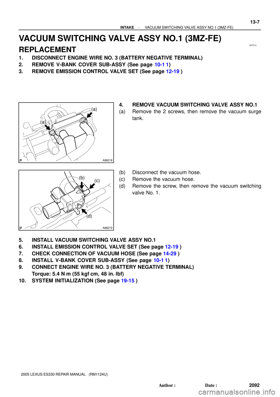
4. REMOVE VACUUM SWITCHING VALVE ASSY NO.1
(a) Remove the 2 screws, then remove the vacuum surge
tank.
(b) Disconnect the vacuum hose.
(c) Remove the vacuum hose.
(d) Remove the screw, then remove the vacuum switching
valve No. 1.
5. INSTALL VACUUM SWITCHING VALVE ASSY NO.1
6. INSTALL EMISSION CONTROL VALVE SET (See page 12-19)
7. CHECK CONNECTION OF VACUUM HOSE (See page 14-29)
8. INSTALL V-BANK COVER SUB-ASSY (See page 10-1 1)
9. CONNECT ENGINE WIRE NO. 3 (BATTERY NEGATIVE TERMINAL)
Torque: 5.4 NVm (55 kgfVcm, 48 in.Vlbf)
10. SYSTEM INITIALIZATION (See page 19-15)
Page 646 of 969
150B8-01
A86209
A86210
(a)
(b)
(a)
(b)
(b)
A86211
Plastic-faced Hammer
15-2
- EXHAUSTEXHAUST PIPE ASSY (3MZ-FE)
2275 Author�: Date�:
2005 LEXUS ES330 REPAIR MANUAL (RM1124U)
Removal & Installation and Disassembly & Reassembly
1. DISCONNECT ENGINE WIRE NO. 3 (BATTERY NEGATIVE TERMINAL)
2. REMOVE HEATED OXYGEN SENSOR (See page 12-24)
SST 09224-00010
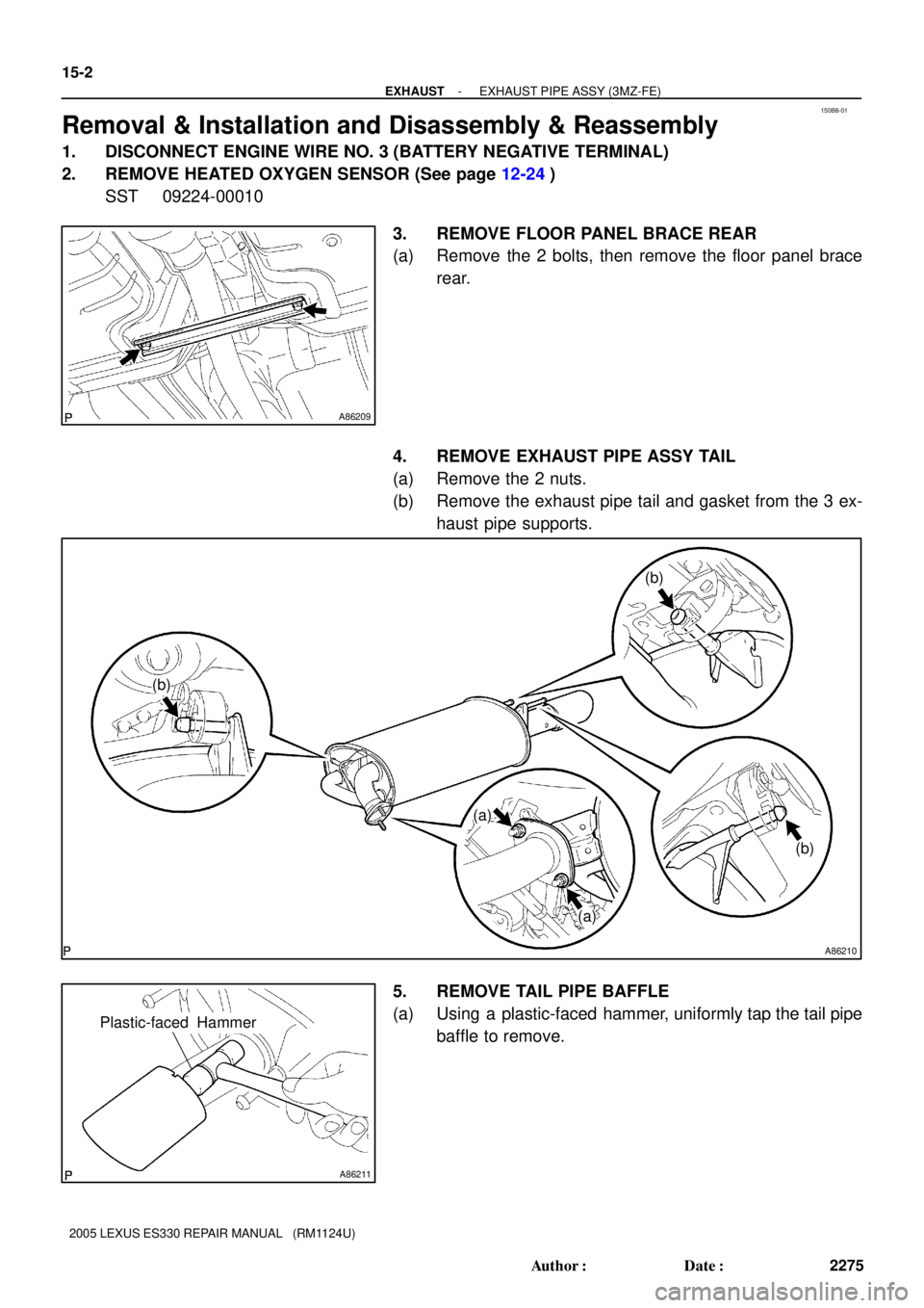
3. REMOVE FLOOR PANEL BRACE REAR
(a) Remove the 2 bolts, then remove the floor panel brace
rear.
4. REMOVE EXHAUST PIPE ASSY TAIL
(a) Remove the 2 nuts.
(b) Remove the exhaust pipe tail and gasket from the 3 ex-
haust pipe supports.
5. REMOVE TAIL PIPE BAFFLE
(a) Using a plastic-faced hammer, uniformly tap the tail pipe
baffle to remove.
Page 649 of 969
A86216
Keyway
KeyPlastic-faced
Hammer
- EXHAUSTEXHAUST PIPE ASSY (3MZ-FE)
15-5
2278 Author�: Date�:
2005 LEXUS ES330 REPAIR MANUAL (RM1124U)
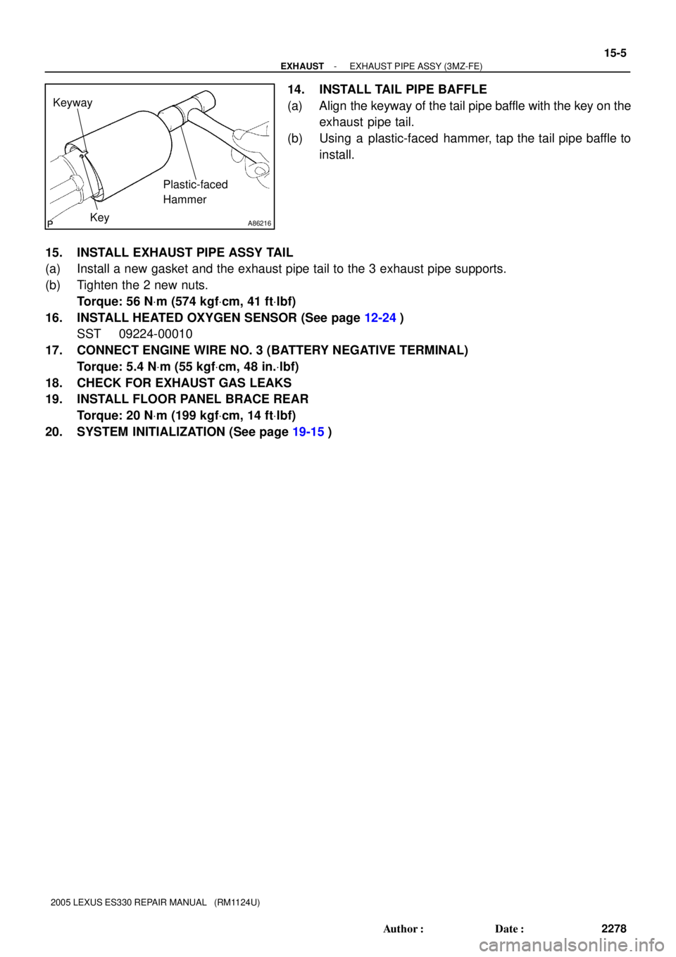
14. INSTALL TAIL PIPE BAFFLE
(a) Align the keyway of the tail pipe baffle with the key on the
exhaust pipe tail.
(b) Using a plastic-faced hammer, tap the tail pipe baffle to
install.
15. INSTALL EXHAUST PIPE ASSY TAIL
(a) Install a new gasket and the exhaust pipe tail to the 3 exhaust pipe supports.
(b) Tighten the 2 new nuts.
Torque: 56 NVm (574 kgfVcm, 41 ftVlbf)
16. INSTALL HEATED OXYGEN SENSOR (See page 12-24)
SST 09224-00010
17. CONNECT ENGINE WIRE NO. 3 (BATTERY NEGATIVE TERMINAL)
Torque: 5.4 NVm (55 kgfVcm, 48 in.Vlbf)
18. CHECK FOR EXHAUST GAS LEAKS
19. INSTALL FLOOR PANEL BRACE REAR
Torque: 20 NVm (199 kgfVcm, 14 ftVlbf)
20. SYSTEM INITIALIZATION (See page 19-15)
Page 653 of 969
A86557
A86558
Ammeter
Battery
A86559
Ammeter
Battery 16-6
- COOLINGCOOLING FAN SYSTEM (3MZ-FE)
2284 Author�: Date�:
2005 LEXUS ES330 REPAIR MANUAL (RM1124U)
(i) Check that the fan and fan No. 2 rotates at low speed.
If not, check the cooling fan relay No. 2, cooling fan relay No.
3 and No. 2 fan.
(j) Reconnect the temperature detect switch No. 2 connec-
tor.
2. INSPECT FAN
(a) Disconnect the fan connector.
(b) Connect battery and ammeter to the fan connector.
(c) Check that the fan rotates smoothly, then check the read-
ing on the ammeter.
Standard amperage: 10.2 to 16.2 A at 20�C (68�F)
(d) Reconnect the fan connector.
3. INSPECT NO. 2 FAN
(a) Disconnect the No. 2 fan connector.
(b) Connect the battery and ammeter to the No. 2 fan con-
nector.
(c) Check that the No. 2 fan rotates smoothly, then check the
reading on the ammeter.
Standard amperage: 10.2 to 16.2 A at 20�C (68�F)
(d) Reconnect the No. 2 fan connector.
Page 656 of 969

16-7
2285 Author�: Date�:
2005 LEXUS ES330 REPAIR MANUAL")
160QE-01
A86576
Ohmmeter
A86577
Ohmmeter Battery
A86578
Ohmmeter Ohmmeter
A86579
Ohmmeter OhmmeterBattery
- COOLINGCOOLING FAN SYSTEM (3MZ-FE)
16-7
2285 Author�: Date�:
2005 LEXUS ES330 REPAIR MANUAL (RM1124U)
INSPECTION
1. INSPECT COOLING FAN RELAY
(a) Check the continuity.
(1) Using an ohmmeter, check for continuity between
the terminals.
Standard:
Tester ConnectionSpecified Condition
1 - 2Continuity
3 - 5No continuity
If the result is not as specified, replace the cooling fan relay.
(b) Check the operation.
(1) Apply battery positive voltage across terminals 1
and 2.
(2) Using an ohmmeter, check that there is continuity
between terminals 3 and 5.
If there is no continuity, replace the cooling fan relay.
2. INSPECT COOLING FAN RELAY NO.2
(a) Check the continuity.
(1) Using an ohmmeter, check for continuity between
the terminals.
Standard:
Tester ConnectionSpecified Condition
1 - 2Continuity
3 - 4Continuity
3 - 5No continuity
If the result is not as specified, replace the cooling fan relay.
(b) Check the operation.
(1) Apply battery positive voltage across terminals 1
and 2.
(2) Using an ohmmeter, check that there is no continu-
ity between terminals 3 and 4.
If there is continuity, replace the cooling fan relay.
(3) Using an ohmmeter, check that there is continuity
between terminals 3 and 5.
If there is no continuity, replace the cooling fan relay.
Page 657 of 969

2286 Author�: Date�:
2005 LEXUS ES330 REPAIR MANUAL (RM1124U)
3. INSPECT COOLING FAN")
A86576
Ohmmeter
A86577
Ohmmeter Battery
A86580
Ohmmeter
A86581
Ohmmeter 16-8
- COOLINGCOOLING FAN SYSTEM (3MZ-FE)
2286 Author�: Date�:
2005 LEXUS ES330 REPAIR MANUAL (RM1124U)
3. INSPECT COOLING FAN RELAY NO.3
(a) Check the continuity.
(1) Using an ohmmeter, check for continuity between
the terminals.
Standard:
Tester ConnectionSpecified Condition
1 - 2Continuity
3 - 5No continuity
If the result is not as specified, replace the cooling fan relay.
(b) Check the operation.
(1) Apply battery positive voltage across terminals 1
and 2.
(2) Using an ohmmeter, check that there is continuity
between terminals 3 and 5.
If there is no continuity, replace the cooling fan relay.
4. INSPECT TEMPERATURE DETECT SWITCH
(a) Check the continuity.
(1) Using an ohmmeter, check for continuity between
the terminals.
Standard:
Coolant TemperatureSpecified Condition
Above 98�C (208�F)Continuity
Below 88�C (190�F)No continuity
If the result is not as specified, replace the temperature detect
switch.
5. INSPECT TEMPERATURE DETECT SWITCH NO.2
(a) Check the continuity.
(1) Using an ohmmeter, check for continuity between
the terminals.
Standard:
Coolant TemperatureSpecified Condition
Above 93�C (199�F)Continuity
Below 83�C (181�F)No continuity
If the result is not as specified, replace the temperature detect
switch.