Page 565 of 969

(b)
Deep Socket
Wrench 19
10-8- ENGINE CONTROL SYSTEMENGINE COOLANT TEMPERATURE
SENSOR (3MZ-FE)
2013 Author�: Date�:
2005 LEXUS ES330 REPAIR MANUAL (RM1124U)
ENGINE COOLANT TEMP")
100J3-02
A86247
(a)
(b)
Deep Socket
Wrench 19
10-8- ENGINE CONTROL SYSTEMENGINE COOLANT TEMPERATURE
SENSOR (3MZ-FE)
2013 Author�: Date�:
2005 LEXUS ES330 REPAIR MANUAL (RM1124U)
ENGINE COOLANT TEMPERATURE SENSOR (3MZ-FE)
REPLACEMENT
1. DISCONNECT ENGINE WIRE NO. 3 (BATTERY NEGATIVE TERMINAL)
2. REMOVE RADIATOR LOWER AIR DEFLECTOR (See page 19-5)
3. DRAIN ENGINE COOLANT (See page 16-9)
4. REMOVE ENGINE COOLANT TEMPERATURE
SENSOR
(a) Disconnect the engine coolant temperature sensor con-
nector.
(b) Using a deep socket wrench 19, remove the engine cool-
ant temperature sensor and gasket.
5. INSTALL ENGINE COOLANT TEMPERATURE SENSOR
(a) Using a deep socket wrench 19, install a new gasket and the engine coolant temperature sensor.
Torque: 20 NVm (200 kgfVcm, 14 ftVlbf)
(b) Connect the engine coolant temperature sensor connector.
6. CONNECT ENGINE WIRE NO. 3 (BATTERY NEGATIVE TERMINAL)
Torque: 5.4 NVm (55 kgfVcm, 48 in.Vlbf)
7. ADD ENGINE COOLANT (See page 16-9)
8. CHECK FOR ENGINE COOLANT LEAKS (See page 16-1)
9. INSTALL RADIATOR LOWER AIR DEFLECTOR
10. SYSTEM INITIALIZATION (See page 19-15)
Page 568 of 969
(a)
(a)
(b) 2 Retainers
Socket Hexagon
Wrench 5
A86252
(a)
(b)
(d)
(e)
(b)
(b)
(b)
(c)
(d)
(e)
(f)
A86253
(a)
(c) (b)
- ENGINE CONTROL SYSTEMTHROTTLE BODY ASSY (3MZ-FE)
10-1")
100J5-01
A86250
A86251
(a)(a)
(a)
(b) 2 Retainers
Socket Hexagon
Wrench 5
A86252
(a)
(b)
(d)
(e)
(b)
(b)
(b)
(c)
(d)
(e)
(f)
A86253
(a)
(c) (b)
- ENGINE CONTROL SYSTEMTHROTTLE BODY ASSY (3MZ-FE)
10-1 1
2016 Author�: Date�:
2005 LEXUS ES330 REPAIR MANUAL (RM1124U)
REPLACEMENT
1. DISCONNECT ENGINE WIRE NO. 3 (BATTERY NEGATIVE TERMINAL)
2. REMOVE RADIATOR LOWER AIR DEFLECTOR (See page 19-5)
3. DRAIN ENGINE COOLANT (See page 19-5)
4. REMOVE FRONT SUSPENSION UPPER BRACE
CENTER (W/O TEMS)
(a) Remove the 4 nuts, then remove the front suspension up-
per brace center and 4 spacers.
(b) Temporarily tighten the 4 nuts.
5. REMOVE V-BANK COVER SUB-ASSY
(a) Using a socket hexagon wrench 5, remove the 3 nuts.
(b) Unfasten the 2 retainers, then remove the V-bank cover.
6. REMOVE AIR CLEANER CAP SUB-ASSY
(a) Disconnect the mass air flow meter connector.
(b) Disconnect the 4 vacuum hoses.
(c) Disconnect the ventilation hose No. 2.
(d) Disconnect the fuel vapor feed hose from the 2 hose
clamps.
(e) Loosen the 2 air cleaner cap bolts.
(f) Loosen the air cleaner hose clamp bolt, then remove the
air cleaner cap.
(g) Remove the air cleaner filter element.
7. REMOVE THROTTLE BODY ASSY
(a) Disconnect the throttle motor connector.
(b) Disconnect the water by-pass hose No. 2.
(c) Disconnect the water by-pass hose No. 3.
Page 569 of 969

(d)
(d)
(d) 10-12
- ENGINE CONTROL SYSTEMTHROTTLE BODY ASSY (3MZ-FE)
2017 Author�: Date�:
2005 LEXUS ES330 REPAIR MANUAL (RM1124U)
(d) Remove the 4 bolts, then remove the throttle body.
(")
A86254
(d)
(d)
(d)
(d) 10-12
- ENGINE CONTROL SYSTEMTHROTTLE BODY ASSY (3MZ-FE)
2017 Author�: Date�:
2005 LEXUS ES330 REPAIR MANUAL (RM1124U)
(d) Remove the 4 bolts, then remove the throttle body.
(e) Remove the gasket from the intake air connector.
8. INSTALL THROTTLE BODY ASSY
(a) Install a new gasket to the intake air connector.
(b) Install the throttle body with the 4 bolts.
Torque: 11 NVm (112 kgfVcm, 8 ftVlbf)
(c) Connect the water by-pass hose No. 3.
(d) Connect the water by-pass hose No. 2.
(e) Connect the throttle motor connector.
9. INSTALL AIR CLEANER CAP SUB-ASSY
Torque: 5.0 NVm (51 kgfVcm, 44 in.Vlbf)
10. CHECK CONNECTION OF VACUUM HOSE (See page 14-29)
11. CONNECT ENGINE WIRE NO. 3 (BATTERY NEGATIVE TERMINAL)
Torque: 5.4 NVm (55 kgfVcm, 48 in.Vlbf)
12. ADD ENGINE COOLANT (See page 16-9)
13. CHECK FOR ENGINE COOLANT LEAKS (See page 16-1)
14. INSTALL V-BANK COVER SUB-ASSY
(a) Fit the 2 retainers, then install the V-bank cover.
(b) Using a socket hexagon wrench 5, tighten the 3 nuts.
Torque: 7.9 NVm (81 kgfVcm, 70 in.Vlbf)
15. INSTALL FRONT SUSPENSION UPPER BRACE CENTER (W/O TEMS)
Torque: 80 NVm (816 kgfVcm, 59 ftVlbf)
16. INSTALL RADIATOR LOWER AIR DEFLECTOR
17. SYSTEM INITIALIZATION (See page 19-15)
Page 573 of 969

(b)
(b)
(b)
(b)
A86263
Fuel Pipe
Clamp
Pinch
Pinch
Pull Out
A75650
Tube Connector
Pipe O-ring Nylon Tube
Quick Connector
A86264
(b) 10-16
- ENGINE CONTROL SYSTEMKNOCK SENSOR (3MZ-")
100J7-02
A86262
(a)
(b)
(b)
(b)
(b)
A86263
Fuel Pipe
Clamp
Pinch
Pinch
Pull Out
A75650
Tube Connector
Pipe O-ring Nylon Tube
Quick Connector
A86264
(b) 10-16
- ENGINE CONTROL SYSTEMKNOCK SENSOR (3MZ-FE)
2021 Author�: Date�:
2005 LEXUS ES330 REPAIR MANUAL (RM1124U)
REPLACEMENT
1. DISCHARGE FUEL SYSTEM PRESSURE (See page 11-1)
2. DISCONNECT ENGINE WIRE NO. 3 (BATTERY NEGATIVE TERMINAL)
3. DRAIN ENGINE COOLANT (See page 16-9)
4. REMOVE FRONT SUSPENSION UPPER BRACE CENTER (W/O TEMS) (See page 10-1 1)
5. REMOVE V-BANK COVER SUB-ASSY (See page 10-1 1)
6. REMOVE AIR CLEANER CAP SUB-ASSY (See page 10-1 1)
7. REMOVE EMISSION CONTROL VALVE SET (See page 11-13)
8. REMOVE INTAKE AIR SURGE TANK (See page 11-13)
9. REMOVE ENGINE MOVING CONTROL ROD
(a) Remove the pipe from the clamp.
(b) Remove the 4 bolts, then remove the engine moving con-
trol rod and radio setting condenser.
10. REMOVE INTAKE MANIFOLD
(a) Disconnect the fuel pipe No. 1.
(1) Remove the fuel pipe clamp.
(2) Pinch the tube connector, then pull out the fuel pipe
No. 1.
NOTICE:
�Check around the quick connector for dirt or mud be-
fore this operation. Remove the dirt if necessary.
�Be careful of mud because the quick connector has
an O-ring which seals the pipe and quick connector
that can be contaminated.
�Do not use any tools in this operation.
�Do not bend or twist the nylon tube. Protect the quick
connector by covering it with a vinyl or plastic bag.
�When the pipe and quick connector are stuck, push
and pull the quick connector to release and pull the
quick connector out carefully.
(b) Disconnect the heater inlet water hose.
Page 576 of 969

10-19
2024 Author�: Date�:
2005 LEXUS ES330 REPAIR MANUAL (RM1124U)
15. INSTALL")
A8626611 10
9 8
5
7
64
3 2
1
A86269
Push
Fuel Pipe
Clamp
A86262
A
B
B
B
- ENGINE CONTROL SYSTEMKNOCK SENSOR (3MZ-FE)
10-19
2024 Author�: Date�:
2005 LEXUS ES330 REPAIR MANUAL (RM1124U)
15. INSTALL INTAKE MANIFOLD
(a) Install the intake manifold with the 9 bolts, 2 nuts and 2
washers. Using several steps, tighten the 9 bolts and 2
nuts uniformly in the sequence shown in the illustration.
Torque: 15 NVm (153 kgfVcm, 11 ftVlbf)
(b) Retighten the 9 water outlet mounting bolts and 2 nuts.
Torque: 15 NVm (153 kgfVcm, 11 ftVlbf)
(c) Install the ground cable with the nut.
Torque: 8.4 NVm (86 kgfVcm, 74 in.Vlbf)
(d) Connect the heater inlet water hose.
(e) Connect the fuel pipe No. 1.
(1) Push in the quick connector to the pipe until it
makes a ºclickº sound.
NOTICE:
�Check the connected part for damage or foreign ob-
jects.
�After connecting, check if the quick connector and
pipe are securely connected by pulling them.
(2) Install the fuel pipe clamp.
16. INSTALL ENGINE MOVING CONTROL ROD
Torque:
23 NVm (235 kgfVcm, 17 ftVlbf) for bolt A
64 NVm (653 kgfVcm, 47 ftVlbf) for bolt B
17. INSTALL INTAKE AIR SURGE TANK (See page 11-13)
18. INSTALL EMISSION CONTROL VALVE SET (See page 11-13)
19. INSTALL AIR CLEANER CAP SUB-ASSY (See page 10-1 1)
20. CHECK CONNECTION OF VACUUM HOSE (See page 14-29)
21. CONNECT ENGINE WIRE NO. 3 (BATTERY NEGATIVE TERMINAL)
Torque: 5.4 NVm (55 kgfVcm, 48 in.Vlbf)
22. ADD ENGINE COOLANT (See page 16-9)
23. CHECK FOR ENGINE COOLANT LEAKS (See page 16-1)
24. CHECK FOR FUEL LEAKS (See page 11-5)
25. INSTALL V-BANK COVER SUB-ASSY (See page 10-1 1)
Page 578 of 969
100J8-01
A86338
(a)
(b)
(b)
- ENGINE CONTROL SYSTEMACCELERATOR PEDAL ASSY (3MZ-FE (NORMAL
PEDAL))10-21
2026 Author�: Date�:
2005 LEXUS ES330 REPAIR MANUAL (RM1124U)
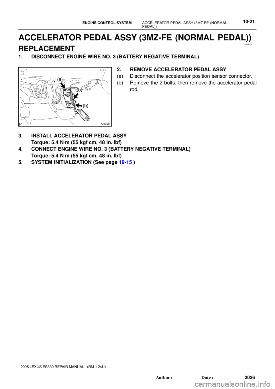
ACCELERATOR PEDAL ASSY (3MZ-FE (NORMAL PEDAL))
REPLACEMENT
1. DISCONNECT ENGINE WIRE NO. 3 (BATTERY NEGATIVE TERMINAL)
2. REMOVE ACCELERATOR PEDAL ASSY
(a) Disconnect the accelerator position sensor connector.
(b) Remove the 2 bolts, then remove the accelerator pedal
rod.
3. INSTALL ACCELERATOR PEDAL ASSY
Torque: 5.4 NVm (55 kgfVcm, 48 in.Vlbf)
4. CONNECT ENGINE WIRE NO. 3 (BATTERY NEGATIVE TERMINAL)
Torque: 5.4 NVm (55 kgfVcm, 48 in.Vlbf)
5. SYSTEM INITIALIZATION (See page 19-15)
Page 579 of 969
100J9-02
A86255
(a)
(b)
(a)
(b)(a)
A86256
(b)
(a)
(b)
(b)
(b)
(b)
(c)
(c)
A86257
(a)
(a)
A86258
(a)
(a) 10-22
- ENGINE CONTROL SYSTEMECM (3MZ-FE)
2027 Author�: Date�:
2005 LEXUS ES330 REPAIR MANUAL (RM1124U)
ECM (3MZ-FE)
REPLACEMENT
1. DISCONNECT ENGINE WIRE NO. 3 (BATTERY NEGATIVE TERMINAL)
2. REMOVE FRONT DOOR SCUFF PLATE RH (See page 71-1 1)
3. REMOVE INSTRUMENT PANEL UNDER COVER SUB-ASSY NO.1 (See page 71-1 1)
4. REMOVE INSTRUMENT PANEL SUB-ASSY LOWER (See page 71-1 1)
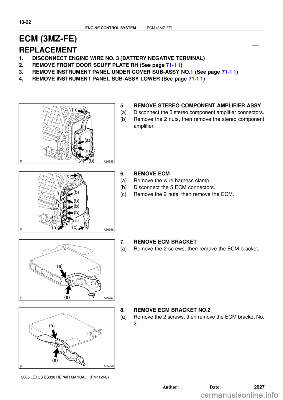
5. REMOVE STEREO COMPONENT AMPLIFIER ASSY
(a) Disconnect the 3 stereo component amplifier connectors.
(b) Remove the 2 nuts, then remove the stereo component
amplifier.
6. REMOVE ECM
(a) Remove the wire harness clamp.
(b) Disconnect the 5 ECM connectors.
(c) Remove the 2 nuts, then remove the ECM.
7. REMOVE ECM BRACKET
(a) Remove the 2 screws, then remove the ECM bracket.
8. REMOVE ECM BRACKET NO.2
(a) Remove the 2 screws, then remove the ECM bracket No.
2.
Page 580 of 969
A86259
(a)
(a)
- ENGINE CONTROL SYSTEMECM (3MZ-FE)
10-23
2028 Author�: Date�:
2005 LEXUS ES330 REPAIR MANUAL (RM1124U)
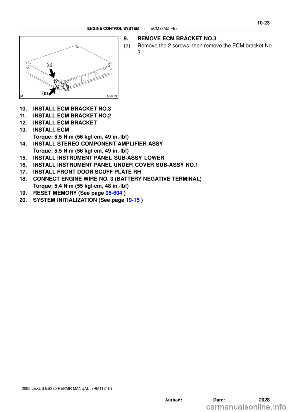
9. REMOVE ECM BRACKET NO.3
(a) Remove the 2 screws, then remove the ECM bracket No
3.
10. INSTALL ECM BRACKET NO.3
11. INSTALL ECM BRACKET NO.2
12. INSTALL ECM BRACKET
13. INSTALL ECM
Torque: 5.5 NVm (56 kgfVcm, 49 in.Vlbf)
14. INSTALL STEREO COMPONENT AMPLIFIER ASSY
Torque: 5.5 NVm (56 kgfVcm, 49 in.Vlbf)
15. INSTALL INSTRUMENT PANEL SUB-ASSY LOWER
16. INSTALL INSTRUMENT PANEL UNDER COVER SUB-ASSY NO.1
17. INSTALL FRONT DOOR SCUFF PLATE RH
18. CONNECT ENGINE WIRE NO. 3 (BATTERY NEGATIVE TERMINAL)
Torque: 5.4 NVm (55 kgfVcm, 48 in.Vlbf)
19. RESET MEMORY (See page 05-604)
20. SYSTEM INITIALIZATION (See page 19-15)