Page 798 of 969

19-17
2349 Author�: Date�:
2005 LEXUS ES330 REPAIR MANUAL (RM1124U)
(b) Check the battery specific gravity.
(")
A01259
A01260
A82941
White Red Blue
B00543
- STARTING & CHARGINGCHARGING SYSTEM (3MZ-FE)
19-17
2349 Author�: Date�:
2005 LEXUS ES330 REPAIR MANUAL (RM1124U)
(b) Check the battery specific gravity.
(1) Check the specific gravity of each cell.
Standard specific gravity: 1.25 to 1.29 at 20�C (68�F)
If the specific gravity is less than specification, charge the bat-
tery.
(c) Check the battery voltage.
(1) If it has been less than 20 minutes since you
stopped driving the vehicle or since the engine was
stopped, turn the ignition switch and electrical sys-
tems (headlight, blower motor, rear defogger etc.)
to the ON position for 60 seconds. This will remove
the surface charge on the battery.
(2) Turn the ignition switch and electrical systems OFF.
(3) Using a voltmeter, measure the battery voltage be-
tween the negative (-) and positive (+) terminals of
the battery.
Standard voltage: 12.5 to 12.9 V at 20�C (68�F)
If the voltage is less than the specification, charge the battery.
(d) Check the indicator as shown in the illustration.
HINT:
�Blue: OK
�White: Charging Necessary
�Red: Insufficient Water
3. INSPECT BATTERY TERMINALS, FUSIBLE LINK AND FUSES
(a) Visually check the battery terminals.
(1) Check that the battery terminals are not loosened or corroded.
(b) Visually check the fusible link and fuses.
(1) Check that there is continuity of the fusible links, high current fuses and regular fuses.
4. INSPECT V-RIBBED BELT
(a) Visually check the belt for excessive wear, frayed cords,
etc.
�If any defects are found, replace the v-ribbed belt.
�Cracks on the rib side of the belt are considered ac-
ceptable.
If the belt has chunks missing from the ribs, it should
be replaced.
Page 799 of 969

2350 Author�: Date�:
2005 LEXUS ES330 REPAIR MANUAL (RM1124U)
(b")
B00540
A88419
Disconnect Wire
from Terminal B
Generator Voltmeter
BatteryAmmeter 19-18
- STARTING & CHARGINGCHARGING SYSTEM (3MZ-FE)
2350 Author�: Date�:
2005 LEXUS ES330 REPAIR MANUAL (RM1124U)
(b) Check that the belt fits properly in the ribbed grooves.
Confirm that the belt has not slipped out of the groove on the
bottom of the pulley by hand.
5. INSPECT GENERATOR WIRING
(a) Visually check the generator wiring.
(1) Check that the wiring is in good condition.
6. INSPECT ABNORMAL NOISES
(a) Listen to abnormal noises from generator.
(1) Check that no abnormal noise is heard from the generator while the engine is running.
7. INSPECT CHARGE WARNING LIGHT CIRCUIT
(a) Turn the ignition switch ON. Check that the charge warning light comes on.
(b) Start the engine, then check that the light goes off.
If the light does not operate as specified, troubleshoot the charge warning light circuit.
8. INSPECT CHARGING CIRCUIT WITHOUT LOAD
(a) If a tester is not available, connect a voltmeter to the
charging circuit as follows.
(1) Disconnect the wire from terminal B of the genera-
tor, then connect it to the negative (-) lead of the
ammeter.
(2) Connect the positive (+) lead of the ammeter to ter-
minal B of the generator.
(3) Connect the positive (+) lead of the voltmeter to ter-
minal B of the generator.
(4) Ground the negative (-) lead of the voltmeter.
(b) Check the charging circuit.
(1) Keep the engine speed at 2,000 rpm, then check
the reading on the ammeter and voltmeter.
Standard amperage: 10 A or less
Standard voltage: 13.2 to 14.8 V
9. INSPECT CHARGING CIRCUIT WITH LOAD
(a) With the engine running at 2,000 rpm, turn the high beam headlights ON and turn the heater blower
switch to the ºHIº position.
(b) Check the reading on the ammeter.
Standard amperage: 30 A or more
�If the ammeter reading is less than the standard amperage, repair the generator.
�If the battery is fully charged, the indication will sometimes be less than the standard amperage.
Page 802 of 969
190SL-01
A86379
(a)
(b)
(c)
(a)
Terminal Cap
A87594
B
AC
A87593
B
A
A87595
(h)
- STARTING & CHARGINGGENERATOR ASSY (3MZ-FE)
19-21
2353 Author�: Date�:
2005 LEXUS ES330 REPAIR MANUAL (RM1124U)
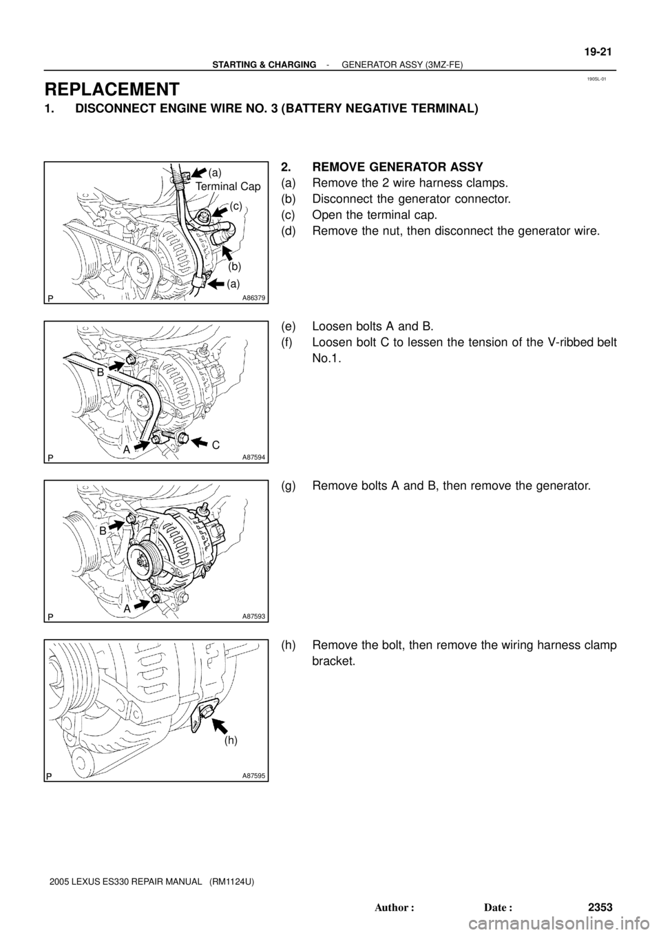
REPLACEMENT
1. DISCONNECT ENGINE WIRE NO. 3 (BATTERY NEGATIVE TERMINAL)
2. REMOVE GENERATOR ASSY
(a) Remove the 2 wire harness clamps.
(b) Disconnect the generator connector.
(c) Open the terminal cap.
(d) Remove the nut, then disconnect the generator wire.
(e) Loosen bolts A and B.
(f) Loosen bolt C to lessen the tension of the V-ribbed belt
No.1.
(g) Remove bolts A and B, then remove the generator.
(h) Remove the bolt, then remove the wiring harness clamp
bracket.
Page 803 of 969
A87593
B
A
A87594
B
AC 19-22
- STARTING & CHARGINGGENERATOR ASSY (3MZ-FE)
2354 Author�: Date�:
2005 LEXUS ES330 REPAIR MANUAL (RM1124U)
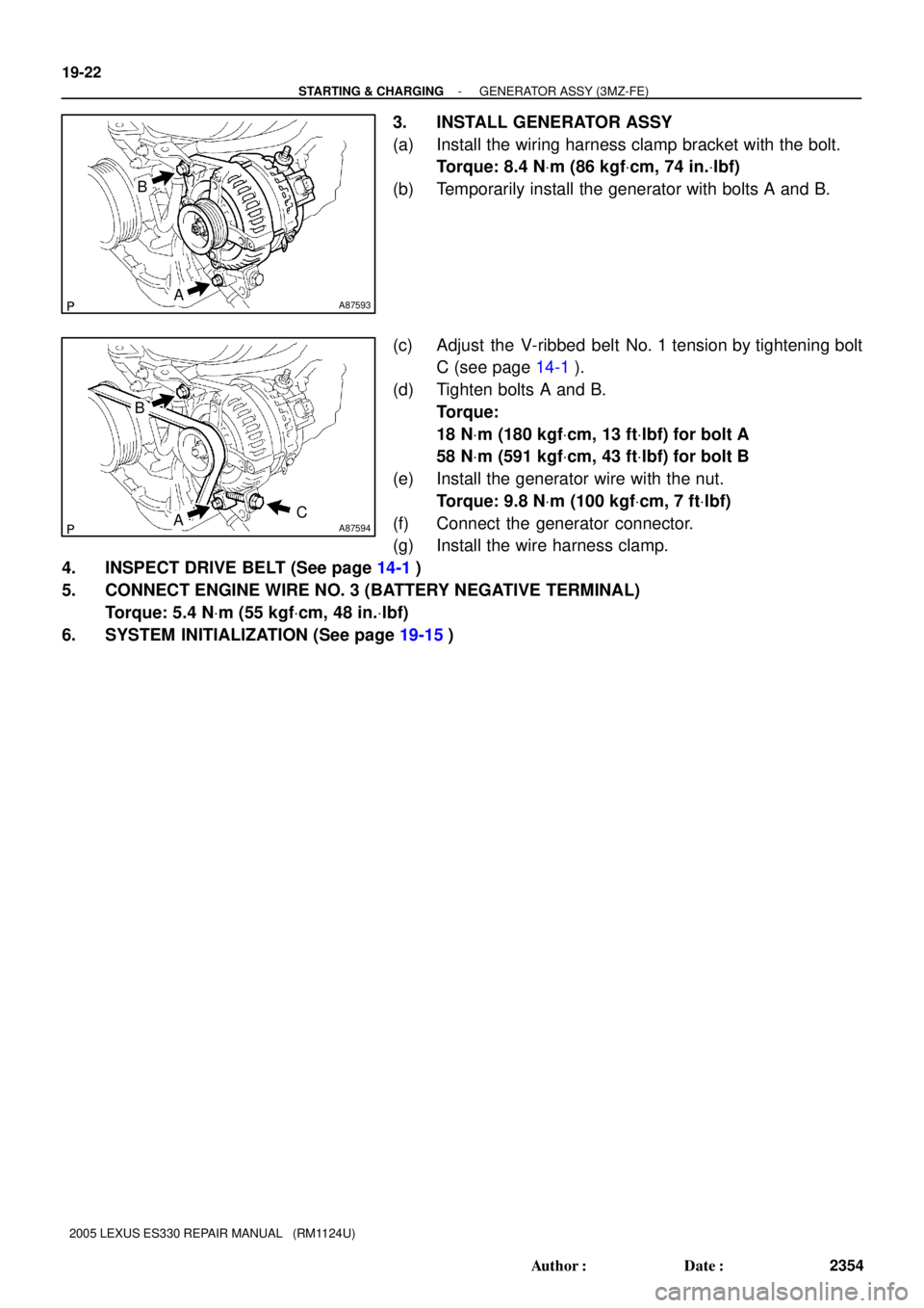
3. INSTALL GENERATOR ASSY
(a) Install the wiring harness clamp bracket with the bolt.
Torque: 8.4 NVm (86 kgfVcm, 74 in.Vlbf)
(b) Temporarily install the generator with bolts A and B.
(c) Adjust the V-ribbed belt No. 1 tension by tightening bolt
C (see page 14-1).
(d) Tighten bolts A and B.
Torque:
18 NVm (180 kgfVcm, 13 ftVlbf) for bolt A
58 NVm (591 kgfVcm, 43 ftVlbf) for bolt B
(e) Install the generator wire with the nut.
Torque: 9.8 NVm (100 kgfVcm, 7 ftVlbf)
(f) Connect the generator connector.
(g) Install the wire harness clamp.
4. INSPECT DRIVE BELT (See page 14-1)
5. CONNECT ENGINE WIRE NO. 3 (BATTERY NEGATIVE TERMINAL)
Torque: 5.4 NVm (55 kgfVcm, 48 in.Vlbf)
6. SYSTEM INITIALIZATION (See page 19-15)
Page 817 of 969

2. DISCONNECT BATTERY NEGATIVE TERMINAL(See page 60-1")
5002I-04
C90684
Matchmarks
SST
C90685
C90686
50-8
- STEERING COLUMNSTEERING COLUMN ASSY
2569 Author�: Date�:
OVERHAUL
1. PRECAUTION(See page 60-1)
2. DISCONNECT BATTERY NEGATIVE TERMINAL(See page 60-1)
3. PLACE FRONT WHEELS FACING STRAIGHT AHEAD
4. REMOVE STEERING WHEEL COVER LOWER NO.2
5. REMOVE CONNECTOR COVER
6. REMOVE STEERING PAD SWITCH
(a) Remove the 2 screws.
(b) Disconnect the connector and remove the steering pad switch.
7. REMOVE HORN BUTTON ASSY(See page 60-22)
8. REMOVE STEERING WHEEL ASSY
(a) Remove the steering wheel assy set nut.
(b) Place matchmarks on the steering wheel assy and steer-
ing main shaft assy.
(c) Using SST, remove the steering wheel assy.
SST 09950- 50013 (09951- 05010, 09952- 05010,
09953-05020, 09954-05021)
9. REMOVE FRONT DOOR SCUFF PLATE LH(See page 71-1 1)
10. REMOVE INSTRUMENT PANEL SUB-ASSY UPPER(See page 71-1 1)
11. REMOVE INSTRUMENT PANEL INSERT SUB-ASSY LOWER LH(See page 71-1 1)
12. REMOVE HEATER TO FOOT DUCT NO.3(See page 71-1 1)
13. REMOVE STEERING COLUMN COVER LWR NO.2
(a) Remove the steering column cover lwr No.2.
14. REMOVE STEERING COLUMN COVER
(a) Remove the 3 screws and steering column cover.
Page 881 of 969

PASSENGER AIRBAG INDICATOR LAMP ± EL002-05 February 22, 2005
Page 2 of 2
MODELPLANTDRIVETRAINPRODUCTION CHANGE EFFECTIVE VIN
ES 330Tsutsumi2WDJTHBA30G#50024130ES 330Kanto2WDJTHBA30G#55068000
TMK2WDJTJGA3#U#50046500
RX 330
TMK4WDJTJHA3#U#50076003RX 330
TMMC2WD2T2GA3#U#5C021700TMMC4WD2T2HA3#U#5C046800
PREVIOUS PART NUMBERCURRENT PART NUMBERPART NAMEQTY
89952±3301089952±33011
Occupant Detection Computer
1
89952±4801089952±48011Occupant Detection Computer1
SPECIAL SERVICE TOOLS (SSTs)PART NUMBERQUANTITY
Lexus Diagnostic Tester Kit*010012701
12 Megabyte Diagnostic Tester Program Card
with version 12.01a Software (or later)*01002593-0051
Occupant Seat Weight Set*
00002±09077±011
* Essential SSTs.
NOTE:
Additional Diagnostic Tester Kits, Program Cards, or other SSTs may be ordered by
calling SPX/OTC at 1-800-933-8335.
1. Unfasten passenger seat and rock the assembly back providing access to the
underside of the seat. For information to unfasten the passenger seat, refer to the
Technical Information System (TIS): 2004 ± 2005 model year ES 330 or RX 330
Repair Manual:
Seat: Front Seat Assembly LH: Overhaul.
2. Disconnect the negative terminal of the vehicle battery.
3. Disconnect electrical connectors from Occupant Detection ECU.
4. Remove and replace the Occupant Detection ECU.
5. Reinstall the seat assembly. For more information, refer to TIS: 2004 ± 2005 model
year ES 330 or RX 330 Repair Manual:
Seat: Front Seat Assembly LH: Overhaul.
Torque: 36.8 N�m (375 kgf�cm, 27 ft�lbf)
6. Reconnect the negative terminal of the vehicle battery.
7. Perform Zero Point Calibration and Sensitivity Check following prompts in the
Diagnostic tool found under the Occupant Detect menu item (refer to
TSIB No. EL007±03, ª
Occupancy Classification System Calibration
(DTC B1150 & B1650)
.º
8. Reinitialize systems affected by the disconnection of the vehicle battery.
Production
Change
Information
Parts
Information
Required
SSTs
Repair
Procedure
Page 889 of 969
PRE±DELIVERY SERVICE (PDS) INFORMATION FOR ES 330 ± PD002-03 August 26, 2003
Page 2 of 9
D.C.C. FUSE INSTALLATION DURING PDS
The D.C.C. fuse has been removed at the assembly plant to reduce parasitic current
draw in transit and storage.
The removed D.C.C. fuse (30 A) is stored in the blank space of the Junction Block in
the engine compartment. The D.C.C. fuse must be reinstalled during Pre±Delivery
Service (PDS) in the dealership as shown below.
Junction Block
Install D.C.C. Fuse (30 A)
Here (Original Location)Remove This Fuse
NOTE:
�Removing the D.C.C. fuse cuts off power sources relating to the Dome, ECU±B and
RAD No. 1 fuses.
�If the vehicle is stored in the dealership for a long period of time after PDS,
disconnect the negative battery terminal to prevent battery discharge. Refer to TSIB
PG009±02 for battery maintenance information.
ITEM NO. 1:
Introduction
Installation
Procedure
Page 892 of 969
 INFORMATION FOR ES 330 ± PD002-03 August 26, 2003
Page 5 of 9
INITIALIZATION OF MOON ROOF
The moon roof is controlled by the sliding roof ECU which detects and memorizes t")
PRE±DELIVERY SERVICE (PDS) INFORMATION FOR ES 330 ± PD002-03 August 26, 2003
Page 5 of 9
INITIALIZATION OF MOON ROOF
The moon roof is controlled by the sliding roof ECU which detects and memorizes the
moon roof position by counting pulses of its motor from the fully tilt±up position as the
start position. Once the battery terminal has been disconnected and reconnected, the
sliding roof ECU does not detect and memorize the moon roof position, resulting in no
functions of the ªone±touch tilt up and down,º ªone±touch slide open and closeº and ªjam
protection.º Please initialize the moon roof position after reconnecting the battery
terminal as outlined below.
1. Turn the ignition switch to the
ªONº position.
2. Push and hold the moon roof switch
to the ªTILT± UPº side until the moon
roof tilts all the way up and then tilts
down slightly (approximately 10 mm
at rear end).
3. Check for proper operation of the
ªOne±touch slide open and closeº and
ªOne±touch tilt up and downº functions
by pushing the switch briefly to the
ªSLIDE OPENº and ªTILT UPº positions.
NOTE:
Jam protection function becomes
effective through the above
initialization procedure.
ITEM NO. 4:
Introduction
Initialization
Procedure
Approx. 10 mm
 INFORMATION FOR ES 330 ± PD002-03 August 26, 2003
Page 2 of 9
D.C.C. FUSE INSTALLATION DURING PDS
The D.C.C. fuse has been removed at the assembly plant to reduce parasiti")