Page 251 of 969

(1) Connect the vinyl tube to the bleeder plug at the
right front wheel or the right rear wheel and loosen
the")
32-6
- BRAKEBRAKE FLUID
2440 Author�: Date�:
2005 LEXUS ES330 REPAIR MANUAL (RM1124U)
(1) Connect the vinyl tube to the bleeder plug at the
right front wheel or the right rear wheel and loosen
the bleeder plug.
(2) Operate the brake actuator assy using the hand-
held tester to bleed the air.
NOTICE:
�The operation stops automatically in 4 seconds.
�At this time, be sure to release the brake pedal.
(3) Check that the operation has stopped, by referring
to the hand-held tester display.
(4) Repeat (2) and (3) until all the air in the fluid is com-
pletely bled out.
(5) Tighten the bleeder plug certainly.
Torque: 8.3 NVm (85 kgfVcm, 73 in.Vlbf)
(6) For the rest of the wheels, bleed the air in the same
way as stated in the above procedure.
(f) Bleed the air out of the pressure reduction line in ºStep3:
Decreaseº on the hand-held tester display.
NOTICE:
�Perform air bleeding by following the steps displayed
on the hand-held tester.
�Make sure that the brake fluid in the master cylinder
reservoir tank does not become empty.
(1) Connect a vinyl tube to either one of the bleeder
plugs.
(2) Loosen the bleeder plug.
(3) Using the hand-held tester, operate the brake ac-
tuator assy using hand-held tester, completely de-
press the brake pedal and keep it.
NOTICE:
�The operation stops automatically in 4 seconds.
When performing this procedure continuously, an in-
terval of at least 20 seconds is required.
�When the operation is completed, the brake pedal
slightly goes down. This is a normal phenomenon
caused when the solenoid opens.
�During this procedure, the pedal seems heavy, but
completely depress it so that the brake fluid comes
out from the bleeder plug.
�Be sure to keep depressing the brake pedal. Never
depress and release the pedal repeatedly.
(4) Tighten the bleeder plug, then release the brake
pedal.
(5) Repeat (2) to (4) until all the air in the fluid is com-
pletely bled out.
(6) Tighten the bleeder plug certainly.
Torque: 8.3 NVm (85 kgfVcm, 73 in.Vlbf)
(7) Repeat the above procedure to bleed the air out of
the brake line for each wheel.
Page 253 of 969

BRAKE PEDAL SUPPORT ASSY
ADJUSTMENT
1. CHEC")
320DV-02
F41697
Stop Lamp
Switch
Push Rod
Pedal Height
32-8
- BRAKEBRAKE PEDAL SUPPORT ASSY
2442 Author�: Date�:
2005 LEXUS ES330 REPAIR MANUAL (RM1124U)
BRAKE PEDAL SUPPORT ASSY
ADJUSTMENT
1. CHECK AND ADJUST BRAKE PEDAL HEIGHT
(a) Inspect brake pedal height.
Pedal height from asphalt sheet:
144.1 - 154.1 mm (5.673 - 6.067 in.)
(b) Adjust brake pedal height.
(1) Remove the instrument panel finish panel sub-
assy lower and instrument panel insert sub-assy
lower LH.
(2) Disconnect the connector from the stop lamp
switch.
(3) Loosen the stop lamp switch lock nut and remove
the stop lamp switch.
(4) Loosen the clevis lock nut.
(5) Adjust the pedal height by turning the pedal push
rod.
(6) Tighten the push rod lock nut.
Torque: 26 NVm (265 kgfVcm, 19 ftVlbf)
(7) Install the stop lamp switch.
(8) Connect the connector to the stop lamp switch.
(9) Push the brake pedal in 5 - 10 mm (0.20 - 0.39 in.),
turn the stop lamp switch to lock the nut in the posi-
tion where the stop lamp goes off.
(10) After installation, push the brake pedal in 5 - 10 mm
(0.20 - 0.39 in.), check that stop lamp lights up.
(11) Install the instrument panel insert sub-assy lower
LH and instrument panel finish panel sub-assy low-
er.
Page 255 of 969
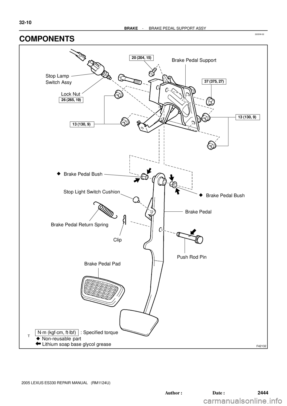
320DW-02
F42132
Brake Pedal Support
Stop Lamp
Switch Assy
Lock Nut
�
Brake Pedal Bush
�
Brake Pedal Bush Stop Light Switch Cushion
Brake Pedal
Push Rod Pin Brake Pedal Return Spring
Clip
Brake Pedal Pad
� Non-reusable part
NVm (kgfVcm, ftVlbf) : Specified torque
Lithium soap base glycol grease
26 (265, 19)
37 (375, 27)
13 (130, 9)
13 (130, 9)
20 (204, 15)
32-10
- BRAKEBRAKE PEDAL SUPPORT ASSY
2444 Author�: Date�:
2005 LEXUS ES330 REPAIR MANUAL (RM1124U)
COMPONENTS
Page 257 of 969

2446 Author�: Date�:
2005 LEXUS ES330 REPAIR MANUAL (RM1124U)
ACCELERATOR &")
320OF-03
F42717
Stop Lamp
Switch Assy
Push Rod
Pedal Height
32-12- BRAKEACCELERATOR & BRAKE PEDAL ASSY (From August,
2002)
2446 Author�: Date�:
2005 LEXUS ES330 REPAIR MANUAL (RM1124U)
ACCELERATOR & BRAKE PEDAL ASSY (From August,
2002)
ADJUSTMENT
1. CHECK AND ADJUST BRAKE PEDAL HEIGHT
(a) Inspect brake pedal height.
Pedal height from asphalt sheet:
144.1 - 154.1 mm (5.673 - 6.067 in.)
(b) Adjust brake pedal height.
(1) Remove the instrument panel finish panel sub-
assy lower and instrument panel insert sub-assy
lower LH.
(2) Disconnect the connector from the stop lamp switch
assy.
(3) Loosen the stop lamp switch lock nut and remove
the stop lamp switch assy.
(4) Loosen the clevis lock nut.
(5) Adjust the pedal height by turning the pedal push
rod.
(6) Tighten the push rod lock nut.
Torque: 26 NVm (265 kgfVcm, 19 ftVlbf)
(7) Install the stop lamp switch assy.
(8) Connect the connector to the stop lamp switch assy.
(9) Push the brake pedal in 5 - 10 mm (0.20 - 0.39 in.),
turn the stop lamp switch assy to lock the nut in the
position where the stop lamp goes off.
(10) After installation, push the brake pedal in 5 - 10 mm
(0.20 - 0.39 in.), check that stop lamp lights up.
(11) Install the instrument panel insert sub-assy lower
LH and instrument panel finish panel sub-assy low-
er.
Page 265 of 969

2454 Author�: Date�:
2005 LEXUS ES330 REPAIR MANUAL (RM1124U)
34. INSTALL BRAKE PEDAL RETURN SPRING
35. INSTALL DRIVER SI")
F16914
F16911
32-20- BRAKEACCELERATOR & BRAKE PEDAL ASSY (From August,
2002)
2454 Author�: Date�:
2005 LEXUS ES330 REPAIR MANUAL (RM1124U)
34. INSTALL BRAKE PEDAL RETURN SPRING
35. INSTALL DRIVER SIDE JUNCTION BLOCK ASSY
(a) Install the junction block assy with the 3 nuts, then con-
nect the each connector.
36. INSTALL STEERING COLUMN ASSY (SEE PAGE 50-8)
37. CONNECT STEERING SLIDING YOKE SUB-ASSY (SEE PAGE 50-8)
38. CONNECT FLOOR SHIFT PARKING LOCK CABLE ASSY (SEE PAGE 50-8)
39. INSPECT CHECK KEY INTERLOCK OPERATION (SEE PAGE 50-8)
40. INSTALL TURN SIGNAL SWITCH ASSY (SEE PAGE 50-8)
41. INSPECT SPIRAL CABLE SUB-ASSY (SEE PAGE 60-31)
42. INSTALL STEERING COLUMN COVER (SEE PAGE 50-8)
43. INSTALL STEERING COLUMN COVER LWR NO.2 (SEE PAGE 50-8)
44. INSTALL HEATER TO FOOT DUCT NO.3 (SEE PAGE 32-14)
45. INSTALL INSTRUMENT PANEL INSERT SUB-ASSY LOWER LH (SEE PAGE 71-1 1)
46. INSTALL INSTRUMENT PANEL SUB-ASSY UPPER (SEE PAGE 71-1 1)
47. INSTALL FRONT DOOR SCUFF PLATE LH (SEE PAGE 71-1 1)
48. PLACE FRONT WHEELS FACING STRAIGHT AHEAD
49. INSTALL STEERING WHEEL ASSY (SEE PAGE 50-8)
50. INSPECT HORN BUTTON ASSY (SEE PAGE 60-22)
51. INSTALL HORN BUTTON ASSY (SEE PAGE 60-22)
52. INSTALL STEERING PAD SWITCH (SEE PAGE 82-1)
53. INSTALL CONNECTOR COVER (SEE PAGE 82-1)
54. INSTALL STEERING WHEEL COVER LOWER NO.2
55. INSPECT SRS WARNING LIGHT (SEE PAGE 05-818)
Page 267 of 969

F41707
F09717
R12236
(A) 32-22
- BRAKEBRAKE MASTER CYLINDER SUB-ASSY
2456 Author�: Date�:
2005 LEXUS ES330 REPAIR MANUAL (RM1124U)
(d) Push in the piston and remove the piston stop")
C69097
R12236
(A)
F41707
F09717
R12236
(A) 32-22
- BRAKEBRAKE MASTER CYLINDER SUB-ASSY
2456 Author�: Date�:
2005 LEXUS ES330 REPAIR MANUAL (RM1124U)
(d) Push in the piston and remove the piston stopper bolt and
gasket.
(e) Remove the No.1 piston sub-assy, pulling straight out not
at an angle.
NOTICE:
If pulled out at an angle, there is a possibility that the cylin-
der bore could be damaged.
(f) Place a waste cloth and 2 wooden blocks on the work
table and lightly edges until the No.2 piston sub-assy
drops out of the cylinder.
HINT:
Make sure the distance (A) from the rag the top of the blocks
is at least 100 mm (3.94 in.).
NOTICE:
If pulled out at an angle, there is a possibility that the cylin-
der bore could be damaged.
9. REMOVE BRAKE MASTER CYLINDER KIT (W/ VSC)
(a) Place master cylinder in vise.
(b) Remove the O-ring.
(c) Push in the piston and remove the snap ring with snap
ring pliers.
NOTICE:
If pulled out at an angle, there is a possibility that the cylin-
der bore could be damaged.
(d) Push in the piston with a screwdriver, and remove the
straight pin by turning over the cylinder body.
HINT:
Tape the screwdriver tip before use.
(e) Remove the No.1 piston sub-assy, pulling straight out not
at an angle.
NOTICE:
If pulled out at an angle, there is a possibility that the cylin-
der bore could be damaged.
(f) Place a waste cloth and 2 wooden blocks on the work
table and lightly edges until the No.2 piston sub-assy
drops out of the cylinder.
HINT:
Make sure the distance (A) from the rag the top of the blocks
is at least 100 mm (3.94 in.).
NOTICE:
If pulled out at an angle, there is a possibility that the cylin-
der bore could be damaged.
Page 269 of 969

(d) Install a straight pin.
HINT:
Insert the No.2 piston with the g")
F09718
F41707
F42650
SST 32-24
- BRAKEBRAKE MASTER CYLINDER SUB-ASSY
2458 Author�: Date�:
2005 LEXUS ES330 REPAIR MANUAL (RM1124U)
(d) Install a straight pin.
HINT:
Insert the No.2 piston with the groove positioning horizontally.
(e) Push in the piston and install the snap ring with snap ring
pliers.
(f) Apply the lithium soap base glycol grease on a new O-
ring and install the O-ring to the master cylinder.
13. INSTALL MASTER CYLINDER RESERVOIR GROMMET
(a) Apply the lithium soap base glycol grease on the 2 master cylinder reservoir grommets.
(b) Install the 2 master cylinder reservoir grommets to the master cylinder reservoir sub-assy.
14. INSTALL BRAKE MASTER CYLINDER RESERVOIR SUB-ASSY
(a) Install the master cylinder reservoir sub-assy to the master cylinder with the screw.
15. INSTALL BRAKE MASTER CYLINDER RESERVOIR STRAINER
(a) Install the brake master cylinder reservoir strainer.
16. INSTALL BRAKE MASTER CYLINDER RESERVOIR FILLER CAP ASSY
(a) Install the brake master cylinder reservoir filler cap assy.
17. INSPECT AND ADJUST BRAKE BOOSTER PUSH
ROD
(a) Apply SST to the master cylinder.
SST 09737-00013
(b) Set SST, on the master cylinder, lower the pin of the SST
until it slightly touches the piston.
(c) Apply the chalk to the flat surfaced tip of the SST pin.
(d) Turn SST upside down and place it clearance between
the brake booster and SST.
Clearance: 0 mm (0 in.)
HINT:
�If there is a clearance between the SST main body and
the booster shell. It means that the specified value, and
no chalk attachment on the booster push rod means that
it is more than the specified value.
�Brake booster push rod clearance before shipment is ad-
justed to be � 0.105 mm (� 0.004 in.).
Page 270 of 969

(e) Using SST, adjust the booster push")
F40006
SST
F40992
F40991
Front Brake Tube
Frame No. 1
- BRAKEBRAKE MASTER CYLINDER SUB-ASSY
32-25
2459 Author�: Date�:
2005 LEXUS ES330 REPAIR MANUAL (RM1124U)
(e) Using SST, adjust the booster push rod length until the
push rod lightly touches the pin head.
SST 09737-00020
18. INSTALL BRAKE MASTER CYLINDER SUB-ASSY
(a) Install the master cylinder sub-assy and 2-way with the
2 nuts.
Torque: 13 NVm (130 kgfVcm, 9 ftVlbf)
(b) Using SST and connect the 4 front brake tubes to the
master cylinder sub-assy.
Torque: 15 NVm (155 kgfVcm, 11 ftVlbf)
SST 09023-00101
(c) Using SST and install the front brake tube frame No.1 to
the master cylinder.
Torque: 15 NVm (155 kgfVcm, 11 ftVlbf)
SST 09023-00101
(d) Connect the level warnig switch connector.
19. FILL RESERVOIR WITH BRAKE FLUID
20. BLEED MASTER CYLINDER (SEE PAGE 32-4)
SST 09023-00101
21. BLEED BRAKE LINE (SEE PAGE 32-4)
22. INSTALL AIR CLEANER ASSY
23. CHECK FLUID LEVEL IN RESERVOIR (SEE PAGE 32-4)
24. CHECK BRAKE FLUID LEAKAGE