Page 2285 of 3419
![INFINITI QX4 2005 Factory Service Manual LAN-6
[CAN]
CAN COMMUNICATION
Revision: October 20052005 QX56
Input/output signal chart
T: Transmit R: Receive
Signals ECM TCMDriver
seat
con-
trol
unitCom-
bina-
tion
meterDis-
play
con-
trol](/manual-img/42/57035/w960_57035-2284.png "INFINITI QX4 2005 Factory Service Manual LAN-6
[CAN]
CAN COMMUNICATION
Revision: October 20052005 QX56
Input/output signal chart
T: Transmit R: Receive
Signals ECM TCMDriver
seat
con-
trol
unitCom-
bina-
tion
meterDis-
play
con-
trol")
LAN-6
[CAN]
CAN COMMUNICATION
Revision: October 20052005 QX56
Input/output signal chart
T: Transmit R: Receive
Signals ECM TCMDriver
seat
con-
trol
unitCom-
bina-
tion
meterDis-
play
con-
trol
unitBCMStee r-
ing
angle
sensorFront
air
control ABS
actua-
tor and
elec-
tric unit
(con-
trol
unit)IPDM
E/R
Engine speed signal T R R R R
Engine status signal T R R
Engine coolant temperature signal T R R R
A/T self-diagnosis signal R T
Accelerator pedal position signal T R R
Closed throttle position signal T R
Wide open throttle position signal T R
Battery voltage signal T R
Key switch signal R T
Ignition switch signal R T R
P range signal T R
Stop lamp switch signal R T
Parking brake switch signal T R
Fuel consumption monitor signalTR
TR
Turbine revolution signal R T
Output shaft revolution signal R T
A/C switch signal R T
A/C compressor request signal T R R
Blower fan motor switch signal R T R
A/C switch/indicator signalTR
RT
Cooling fan speed request signal T R R
Position light request signal R T R
Low beam request signal T R
Low beam status signal RT
High beam request signal R T R
High beam status signal RT
Front fog light request signal T R
Day time running light request signal T R
Vehicle speed signalRRT
RRRTRR R
Sleep wake up signal R T R
Door switch signal R R R T R
Turn indicator signal R T
Key fob ID signal R T
Key fob door unlock signal R T
Buzzer output signal R T
Page 2287 of 3419
LAN-8
[CAN]
CAN COMMUNICATION
Revision: October 20052005 QX56
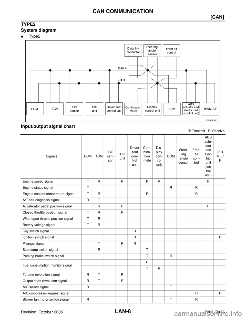
TYPE2
System diagram
�Type2
Input/output signal chart
T: Transmit R: Receive
PKIA8134E
Signals ECM TCMICC
sen-
sorICC
unitDriver
seat
con-
trol
unitCom-
bina-
tion
mete
rDis-
play
con-
trol
unitBCMSteer-
ing
angle
sensorFront
air
con-
trol ABS
actu-
ator
and
elec-
tric
unit
(con-
trol
unit)IPD
M E/
R
Engine speed signal T R R R R R
Engine status signal T R R
Engine coolant temperature signal T R R R
A/T self-diagnosis signal R T
Accelerator pedal position signal T R R R
Closed throttle position signal T R R
Wide open throttle position signal T R
Battery voltage signal T R
Key switch signal R T
Ignition switch signal R T R
P range signal T R R
Stop lamp switch signal R T
Parking brake switch signal T R
Fuel consumption monitor signalTR
TR
Turbine revolution signal R T R
Output shaft revolution signal R T R
A/C switch signal R T
A/C compressor request signal T R R
Blower fan motor switch signal R T R
Page 2290 of 3419
![INFINITI QX4 2005 Factory Service Manual CAN COMMUNICATION
LAN-11
[CAN]
C
D
E
F
G
H
I
J
L
MA
B
LAN
Revision: October 20052005 QX56
Input/output signal chart
T: Transmit R: Receive
Signals ECM TCMDriver
seat
con-
trol
unitCom-
bina-
tion](/manual-img/42/57035/w960_57035-2289.png "INFINITI QX4 2005 Factory Service Manual CAN COMMUNICATION
LAN-11
[CAN]
C
D
E
F
G
H
I
J
L
MA
B
LAN
Revision: October 20052005 QX56
Input/output signal chart
T: Transmit R: Receive
Signals ECM TCMDriver
seat
con-
trol
unitCom-
bina-
tion")
CAN COMMUNICATION
LAN-11
[CAN]
C
D
E
F
G
H
I
J
L
MA
B
LAN
Revision: October 20052005 QX56
Input/output signal chart
T: Transmit R: Receive
Signals ECM TCMDriver
seat
con-
trol
unitCom-
bina-
tion
meterDis-
play
con-
trol
unitBCMStee r-
ing
angle
sen-
sorFront
air
con-
trolTran s-
fer
con-
trol
unitABS
actua-
tor
and
elec-
tric
unit
(con-
trol
unit)IPDM
E/R
A/T self-diagnosis signal R T
Stop lamp switch signal R T
Parking brake switch signal T R
Battery voltage signal T R
Key switch signal R T
Ignition switch signal R T R
P range signal T R
Closed throttle position signal T R
Wide open throttle position signal T R
Engine speed signal T R R R R R
Engine status signal T R R
Engine coolant temperature signal T R R R
Accelerator pedal position signal T R R R
Fuel consumption monitor signalTR
TR
Turbine revolution signal R T
Output shaft revolution signal R T R
A/C switch signal R T
A/C compressor request signal T R R
Blower fan motor switch signal R T R
A/C switch/indicator signalTR
RT
Cooling fan speed request signal T R R
Position light request signal R T R
Low beam request signal T R
Low beam status signal RT
High beam request signal R T R
High beam status signal RT
Front fog light request signal T R
Day time running light request signal T R
Vehicle speed signalRRRT
RRRT RR R
Sleep wake up signal R T R
Door switch signal R R R T R
Turn indicator signal R T
Key fob ID signal R T
Key fob door unlock signal R T
Page 2292 of 3419
![INFINITI QX4 2005 Factory Service Manual CAN COMMUNICATION
LAN-13
[CAN]
C
D
E
F
G
H
I
J
L
MA
B
LAN
Revision: October 20052005 QX56
TYPE 4
System diagram
�Ty p e 4
Input/output signal chart
T: Transmit R: Receive
PKIA8135E
Signals ECM TCMIC](/manual-img/42/57035/w960_57035-2291.png "INFINITI QX4 2005 Factory Service Manual CAN COMMUNICATION
LAN-13
[CAN]
C
D
E
F
G
H
I
J
L
MA
B
LAN
Revision: October 20052005 QX56
TYPE 4
System diagram
�Ty p e 4
Input/output signal chart
T: Transmit R: Receive
PKIA8135E
Signals ECM TCMIC")
CAN COMMUNICATION
LAN-13
[CAN]
C
D
E
F
G
H
I
J
L
MA
B
LAN
Revision: October 20052005 QX56
TYPE 4
System diagram
�Ty p e 4
Input/output signal chart
T: Transmit R: Receive
PKIA8135E
Signals ECM TCMICC
sen-
sorICC
unitDriver
seat
con-
trol
unitCom-
bina-
tion
mete
rDis-
play
con-
trol
unitBCMStee r-
ing
angle
sen-
sorFront
air
con-
trolTra ns -
fer
con-
trol
unitABS
actu-
ator
and
elec-
tric
unit
(con-
trol
unit)IPD
M
E/R
A/T self-diagnosis signal R T
Stop lamp switch signal R T
Parking brake switch signal T R
Battery voltage signal T R
Key switch signal R T
Ignition switch signal R T R
P range signal T R R
Closed throttle position signal T R R
Wide open throttle position signal T R
Engine speed signal T R R R R R R
Engine status signal T R R
Engine coolant temperature sig-
nalTR R R
Accelerator pedal position signal T R R R R
Fuel consumption monitor signalTR
TR
Turbine revolution signal R T R
Output shaft revolution signal R T R R
A/C switch signal R T
A/C compressor request signal T R R
Blower fan motor switch signal R T R
Page 2300 of 3419
![INFINITI QX4 2005 Factory Service Manual CAN SYSTEM (TYPE 1)
LAN-21
[CAN]
C
D
E
F
G
H
I
J
L
MA
B
LAN
Revision: October 20052005 QX56
Work FlowUKS0018G
1. When there are no indications of “AUTO DRIVE POS.”, “BCM”, “HVAC” or “IPD](/manual-img/42/57035/w960_57035-2299.png "INFINITI QX4 2005 Factory Service Manual CAN SYSTEM (TYPE 1)
LAN-21
[CAN]
C
D
E
F
G
H
I
J
L
MA
B
LAN
Revision: October 20052005 QX56
Work FlowUKS0018G
1. When there are no indications of “AUTO DRIVE POS.”, “BCM”, “HVAC” or “IPD")
CAN SYSTEM (TYPE 1)
LAN-21
[CAN]
C
D
E
F
G
H
I
J
L
MA
B
LAN
Revision: October 20052005 QX56
Work FlowUKS0018G
1. When there are no indications of “AUTO DRIVE POS.”, “BCM”, “HVAC” or “IPDM E/R” on “SELECT SYS-
TEM” display of CONSULT-II, print the “SELECT SYSTEM”.
2. Print all the data of “SELF-DIAG RESULTS” for “ENGINE”, “A/T”, “AUTO DRIVE POS.”, “BCM”, “HVAC”,
“ABS” and “IPDM E/R” displayed on CONSULT-II.
3. Print all the data of “CAN DIAG SUPPORT MNTR” for “ENGINE”, “A/T”, “AUTO DRIVE POS.”, “BCM”,
“HVAC”, “ABS” and “IPDM E/R” displayed on CONSULT-II.
4. Attach the printed sheet of “SELECT SYSTEM”, “SELF-DIAG RESULTS” and “CAN DIAG SUPPORT
MNTR” onto the check sheet. Refer to LAN-23, "
CHECK SHEET" .
5. Based on the indications of “SELECT SYSTEM” and the results of “CAN DIAG SUPPORT MNTR”, put
marks “v” onto the items with “No indication”, “NG” or “UNKWN” in the check sheet table. Refer to LAN-23,
"CHECK SHEET" .
NOTE:
�If “NG” is displayed on “INITIAL DIAG (Initial diagnosis)” as “CAN DIAG SUPPORT MNTR” for the diag-
nosed control unit, replace the control unit.
�The “CAN DIAG SUPPORT MNTR” items, which are not in check sheet table, are not related to diag-
nostic procedure on service manual.
So it is not necessary to check the status of the “CAN DIAG SUPPORT MNTR” items not in check
sheet table.
6. Check CAN communication line of the navigation system. Refer to AV-131, "
CAN Communication Line
Check" .
7. Attach the CAN DIAG SUPPORT MONITOR check sheet onto the check sheet. Refer to LAN-23,
"CHECK SHEET" .
PKIA2093E
PKIA8260E
PKIA8343E
Page 2334 of 3419
![INFINITI QX4 2005 Factory Service Manual CAN SYSTEM (TYPE 2)
LAN-55
[CAN]
C
D
E
F
G
H
I
J
L
MA
B
LAN
Revision: October 20052005 QX56
Work FlowUKS001N7
1. When there are no indications of “AUTO DRIVE POS.”, “BCM”, “HVAC” or “IPD](/manual-img/42/57035/w960_57035-2333.png "INFINITI QX4 2005 Factory Service Manual CAN SYSTEM (TYPE 2)
LAN-55
[CAN]
C
D
E
F
G
H
I
J
L
MA
B
LAN
Revision: October 20052005 QX56
Work FlowUKS001N7
1. When there are no indications of “AUTO DRIVE POS.”, “BCM”, “HVAC” or “IPD")
CAN SYSTEM (TYPE 2)
LAN-55
[CAN]
C
D
E
F
G
H
I
J
L
MA
B
LAN
Revision: October 20052005 QX56
Work FlowUKS001N7
1. When there are no indications of “AUTO DRIVE POS.”, “BCM”, “HVAC” or “IPDM E/R” on “SELECT SYS-
TEM” display of CONSULT-II, print the “SELECT SYSTEM”.
2. Print all the data of “SELF-DIAG RESULTS” for “ENGINE”, “A/T”, “ICC”, “AUTO DRIVE POS.”, “BCM”,
“HVAC”, “ABS” and “IPDM E/R” displayed on CONSULT-II.
3. Print all the data of “CAN DIAG SUPPORT MNTR” for “ENGINE”, “A/T”, “ICC”, “AUTO DRIVE POS.”,
“BCM”, “HVAC”, “ABS” and “IPDM E/R” displayed on CONSULT-II.
4. Attach the printed sheet of “SELECT SYSTEM”, “SELF-DIAG RESULTS” and “CAN DIAG SUPPORT
MNTR” onto the check sheet. Refer to LAN-57, "
CHECK SHEET" .
5. Based on the indications of “SELECT SYSTEM” and the results of “CAN DIAG SUPPORT MNTR”, put
marks “v” onto the items with “No indication”, “NG” or “UNKWN” in the check sheet table. Refer to LAN-57,
"CHECK SHEET" .
NOTE:
�If “NG” is displayed on “INITIAL DIAG (Initial diagnosis)” as “CAN DIAG SUPPORT MNTR” for the diag-
nosed control unit, replace the control unit.
�The “CAN DIAG SUPPORT MNTR” items, which are not in check sheet table, are not related to diag-
nostic procedure on service manual.
So it is not necessary to check the status of the “CAN DIAG SUPPORT MNTR” items not in check
sheet table.
6. Check CAN communication line of the navigation system. Refer to AV-131, "
CAN Communication Line
Check" .
7. Attach the CAN DIAG SUPPORT MONITOR check sheet onto the check sheet. Refer to LAN-57,
"CHECK SHEET" .
PKIA2093E
PKIA8260E
PKIA8343E
Page 2374 of 3419
![INFINITI QX4 2005 Factory Service Manual CAN SYSTEM (TYPE 3)
LAN-95
[CAN]
C
D
E
F
G
H
I
J
L
MA
B
LAN
Revision: October 20052005 QX56
Work FlowUKS0019V
1. When there are no indications of “AUTO DRIVE POS.”, “BCM”, “HVAC”, “ALL M](/manual-img/42/57035/w960_57035-2373.png "INFINITI QX4 2005 Factory Service Manual CAN SYSTEM (TYPE 3)
LAN-95
[CAN]
C
D
E
F
G
H
I
J
L
MA
B
LAN
Revision: October 20052005 QX56
Work FlowUKS0019V
1. When there are no indications of “AUTO DRIVE POS.”, “BCM”, “HVAC”, “ALL M")
CAN SYSTEM (TYPE 3)
LAN-95
[CAN]
C
D
E
F
G
H
I
J
L
MA
B
LAN
Revision: October 20052005 QX56
Work FlowUKS0019V
1. When there are no indications of “AUTO DRIVE POS.”, “BCM”, “HVAC”, “ALL MODE AWD/4WD” or
“IPDM E/R” on “SELECT SYSTEM” display of CONSULT-II, print the “SELECT SYSTEM”.
2. Print all the data of “SELF-DIAG RESULTS” for “ENGINE”, “A/T”, “AUTO DRIVE POS.”, “BCM”, “HVAC”,
“ALL MODE AWD/4WD”, “ABS” and “IPDM E/R” displayed on CONSULT-II.
3. Print all the data of “CAN DIAG SUPPORT MNTR” for “ENGINE”, “A/T”, “AUTO DRIVE POS.”, “BCM”,
“HVAC”, “ALL MODE AWD/4WD”, “ABS” and “IPDM E/R” displayed on CONSULT-II.
4. Attach the printed sheet of “SELECT SYSTEM”, “SELF-DIAG RESULTS” and “CAN DIAG SUPPORT
MNTR” onto the check sheet. Refer to LAN-97, "
CHECK SHEET" .
5. Based on the indications of “SELECT SYSTEM” and the results of “CAN DIAG SUPPORT MNTR”, puts a
check mark onto the items with “No indication”, “NG” or “UNKWN” in the check sheet table. Refer to LAN-
97, "CHECK SHEET" .
CAUTION:
“ALL MODE AWD/4WD” puts a check mark on the check
sheet when “Present” is “UNKWN” and “Past” is “0”.
PKIA2093E
PKIA8260E
PKIA8343E
SKIB3244E
Page 2410 of 3419
![INFINITI QX4 2005 Factory Service Manual CAN SYSTEM (TYPE 4)
LAN-131
[CAN]
C
D
E
F
G
H
I
J
L
MA
B
LAN
Revision: October 20052005 QX56
Work FlowUKS001NT
1. When there are no indications of “AUTO DRIVE POS.”, “BCM”, “HVAC”, “ALL](/manual-img/42/57035/w960_57035-2409.png "INFINITI QX4 2005 Factory Service Manual CAN SYSTEM (TYPE 4)
LAN-131
[CAN]
C
D
E
F
G
H
I
J
L
MA
B
LAN
Revision: October 20052005 QX56
Work FlowUKS001NT
1. When there are no indications of “AUTO DRIVE POS.”, “BCM”, “HVAC”, “ALL")
CAN SYSTEM (TYPE 4)
LAN-131
[CAN]
C
D
E
F
G
H
I
J
L
MA
B
LAN
Revision: October 20052005 QX56
Work FlowUKS001NT
1. When there are no indications of “AUTO DRIVE POS.”, “BCM”, “HVAC”, “ALL MODE AWD/4WD” or
“IPDM E/R” on “SELECT SYSTEM” display of CONSULT-II, print the “SELECT SYSTEM”.
2. Print all the data of “SELF-DIAG RESULTS” for “ENGINE”, “A/T”, “ICC”, “AUTO DRIVE POS.”, “BCM”,
“HVAC”, “ALL MODE AWD/4WD”, “ABS” and “IPDM E/R” displayed on CONSULT-II.
3. Print all the data of “CAN DIAG SUPPORT MNTR” for “ENGINE”, “A/T”, “ICC”, “AUTO DRIVE POS.”,
“BCM”, “HVAC”, “ALL MODE AWD/4WD”, “ABS” and “IPDM E/R” displayed on CONSULT-II.
4. Attach the printed sheet of “SELECT SYSTEM”, “SELF-DIAG RESULTS” and “CAN DIAG SUPPORT
MNTR” onto the check sheet. Refer to LAN-133, "
CHECK SHEET" .
5. Based on the indications of “SELECT SYSTEM” and the results of “CAN DIAG SUPPORT MNTR”, puts a
check mark onto the items with “No indication”, “NG” or “UNKWN” in the check sheet table. Refer to LAN-
133, "CHECK SHEET" .
CAUTION:
“ALL MODE AWD/4WD” puts a check mark on the check
sheet when “Present” is “UNKWN” and “Past” is “0”.
PKIA2093E
PKIA8260E
PKIA8343E
SKIB3244E