Page 2063 of 3419

Revision: October 20052005 QX56
SERVICE DATA AND SPECIFICATIONS (SDS)PFP:00030
General SpecificationsEDS003PM
Side Gear AdjustmentEDS003PN
Total Preload Ad")
FFD-32
SERVICE DATA AND SPECIFICATIONS (SDS)
Revision: October 20052005 QX56
SERVICE DATA AND SPECIFICATIONS (SDS)PFP:00030
General SpecificationsEDS003PM
Side Gear AdjustmentEDS003PN
Total Preload AdjustmentEDS003PO
EngineVK56E
Vehicle gradeAll
Front final driveM205
2-pinion
Gear ratio 2.937 3.357
Number of teeth (drive gear/drive pinion) 47/16 47/14
Oil capacity (approximate)
1.6 (3 3/8 US pt , 2 7/8 Imp pt)
Side gear to pinion mate gear backlash (Clearance between side gear
thrust washer and differential case) mm (in)less than 0.20 (0.0079) or less
Available side
gear thrust
washersThickness mm (in) Package part number*
0.76 (0.030)
0.79 (0.031)
0.81 (0.032)
0.84 (0.033)
0.87 (0.034)38424 8S111
0.89 (0.035)
0.91 (0.036)
0.94 (0.037)
0.97 (0.038)
0.99 (0.039)38424 8S112
Total preload N·m (Kg-m, in-lb)Gear ratio 2.937 Type Gear ratio 3.357 type
3.09 - 4.87 (0.32 - 0.49, 28 - 43) 2.98 - 4.76 (0.31 - 0.48, 27 - 42)
Drive gear to drive pinion backlash mm (in) 0.13 - 0.18 (0.0051 - 0.0071)
Page 2066 of 3419

FL-1
FUEL SYSTEM
B ENGINE
CONTENTS
C
D
E
F
G
H
I
J
K
L
M
SECTION FL
A
FL
Revision: October 20052005 QX56 PREPARATION ........................................................... 2
Special Service Tools ............................................... 2
Commercial Service Tool ......................................... 2
FUEL SYSTEM ........................................................... 3
Checking Fuel Lines ................................................. 3
General Precautions ................................................ 3
FUEL LEVEL SENSOR UNIT, FUEL FILTER AND
FUEL PUMP ASSEMBLY ........................................... 5
Removal and Installation .......................................... 5
REMOVAL ............................................................. 5
INSTALLATION ..................................................... 8
INSPECTION AFTER INSTALLATION ................. 8FUEL TANK ................................................................ 9
Removal and Installation .......................................... 9
REMOVAL ........................................................... 10
INSTALLATION ................................................... 13
INSPECTION AFTER INSTALLATION ................ 13
SERVICE DATA AND SPECIFICATIONS (SDS) ...... 14
Standard and Limit .................................................. 14
Page 2069 of 3419
FL-4Revision: October 2005
FUEL SYSTEM
2005 QX56
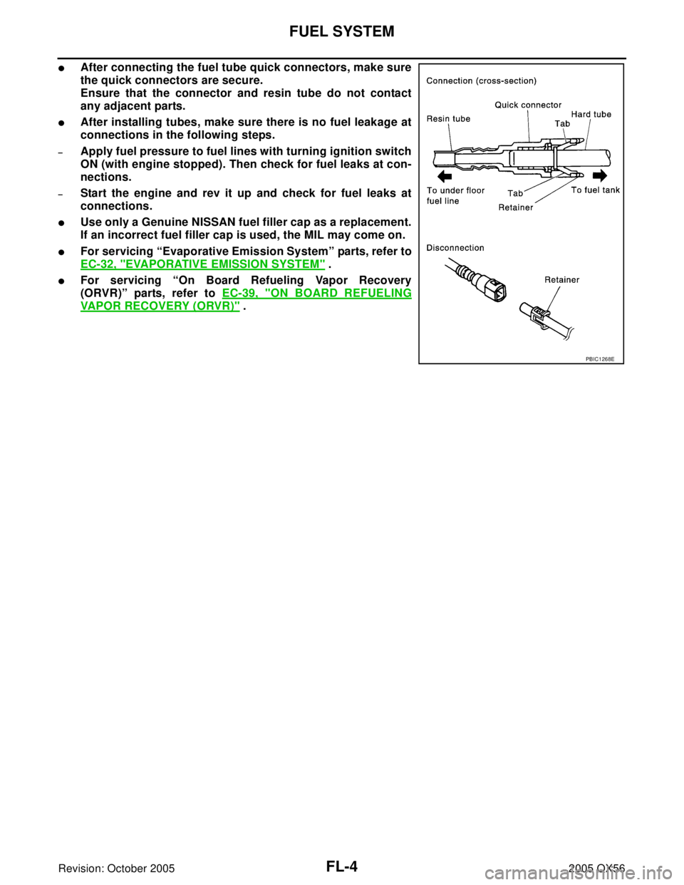
�After connecting the fuel tube quick connectors, make sure
the quick connectors are secure.
Ensure that the connector and resin tube do not contact
any adjacent parts.
�After installing tubes, make sure there is no fuel leakage at
connections in the following steps.
–Apply fuel pressure to fuel lines with turning ignition switch
ON (with engine stopped). Then check for fuel leaks at con-
nections.
–Start the engine and rev it up and check for fuel leaks at
connections.
�Use only a Genuine NISSAN fuel filler cap as a replacement.
If an incorrect fuel filler cap is used, the MIL may come on.
�For servicing “Evaporative Emission System” parts, refer to
EC-32, "
EVAPORATIVE EMISSION SYSTEM" .
�For servicing “On Board Refueling Vapor Recovery
(ORVR)” parts, refer to EC-39, "
ON BOARD REFUELING
VAPOR RECOVERY (ORVR)" .
PBIC1268E
Page 2073 of 3419

FL-8Revision: October 2005
FUEL LEVEL SENSOR UNIT, FUEL FILTER AND FUEL PUMP ASSEMBLY
2005 QX56
11. Remove the lock ring using Tool.
12. Remove the fuel level sensor, fuel filter, and fuel pump assem-
bly.
CAUTION:
�Do not bend the float arm during removal.
�Avoid impacts such as dropping when handling the com-
ponents.
INSTALLATION
Installation is in the reverse order of removal.
�Connect the quick connector as follows:
–Check the connection for any damage or foreign materials.
–Align the connector with the pipe, then insert the connector straight into the pipe until a click is heard.
–After connecting the quick connector, make sure that the con-
nection is secure by checking as follows:
–Pull the tube and the connector to make sure they are securely
connected.
–Visually inspect the connector to make sure the two retainer tabs
are securely connected.
INSPECTION AFTER INSTALLATION
1. Turn the ignition switch ON but do not start engine, then check the fuel pipes and hose connections for
leaks while applying fuel pressure to the system.
2. Start the engine and rev it above idle speed, then check that there are no fuel leaks at any of the fuel pipe
and hose connections.Tool number : — (J-46536)
LBIA0389E
PBIC1653E
Page 2078 of 3419

FUEL TANK
FL-13
C
D
E
F
G
H
I
J
K
L
MA
FL
Revision: October 20052005 QX56
19. Remove the fuel tank strap bolts while supporting the fuel tank
with a suitable lift jack.
20. Disconnect the EVAP hose from the molded clip in the top of the fuel tank while lowering the fuel tank.
21. Lower the fuel tank using a suitable lift jack and remove it.
22. If necessary, remove the lock ring using Tool.
23. If necessary, remove the fuel level sensor, fuel filter, and fuel
pump assembly.
CAUTION:
�Do not bend the float arm during removal.
�Avoid impacts such as dropping when handling the com-
ponents.
INSTALLATION
Installation is in the reverse order of removal.
�Connect the quick connector as follows:
–Check the connection for any damage or foreign materials.
–Align the connector with the pipe, then insert the connector straight into the pipe until a click is heard.
–After connecting the quick connector, make sure that the con-
nection is secure by checking as follows:
–Pull the tube and the connector to make sure they are securely
connected.
–Visually inspect the connector to make sure the two retainer tabs
are securely connected.
INSPECTION AFTER INSTALLATION
1. Turn the ignition switch ON but do not start engine, then check the fuel pipe and hose connections for
leaks while applying fuel pressure.
2. Start the engine and rev it above idle, then check that there are no fuel leaks at any of the fuel pipe and
hose connections.
LBIA0387E
Tool number : — (J-46536)
LBIA0389E
PBIC1653E
Page 2081 of 3419
FSU-2
PRECAUTIONS
Revision: October 20052005 QX56
PRECAUTIONSPFP:00001
PrecautionsEES001GD
�When installing the rubber bushings, the final tightening must be done under unladen condition and with
the tires on level ground. Oil will shorten the life of the rubber bushings, so wipe off any spilled oil immedi-
ately.
�Unladen condition means the fuel tank, engine coolant and lubricants are at the full specification. The
spare tire, jack, hand tools, and mats are in their designated positions.
�After installing suspension components, check the wheel alignment.
�Lock nuts are not reusable. Always use new lock nuts for installation. New lock nuts are pre-oiled, do not
apply any additional lubrication.
Page 2087 of 3419
.
2. Push the vehicle straight ahead about 5 m (16 ft).
3.")
FSU-8
ON-VEHICLE SERVICE
Revision: October 20052005 QX56
1. Bounce the front of vehicle up and down to stabilize the vehicle height (posture).
2. Push the vehicle straight ahead about 5 m (16 ft).
3. Put a mark on base line of the tread (rear side) of both front tires
at the same height as hub center as shown. These marks are
measuring points.
4. Measure the distance “A” on the rear side of the front tires as
shown.
5. Push the vehicle slowly ahead to rotate the wheels 180°
degrees (1/2 a turn).
CAUTION:
If the wheels have rotated more than 180° degrees (1/2
turn), start this procedure again from the beginning. Never
push the vehicle backward.
6. Measure the distance “B” on the front side of the front tires at the
same marks as shown. Total toe-in is calculated as “A” – “B”.
7. Adjust the toe-in by varying the length of the steering outer
socket.
a. Loosen the outer tie-rod lock nuts.
b. Adjust the toe-in by screwing the outer tie-rods in or out.
c. Tighten the outer tie-rod lock nuts to specification.
FRONT WHEEL TURNING ANGLE
NOTE:
Check front wheel turning angle after the toe-in inspection.
1. Place front wheels on turning radius gauges in straight ahead
position and rear wheels on stands so that vehicle can be level.
Check the maximum inner and outer wheel turning angles for LH
and RH road wheels.
2. Start engine and run at idle, turn steering wheel all the way right
and left, measure the turning angle.
�Any turning angles are not adjustable. If any of steering
angles are out of the specification, check if the following parts
are worn or damaged.
–Steering gear
–Steering column
–Front suspension components
AFA05 0
Total toe-in : Refer to FSU-20, "Wheel Alignment
(Unladen*1 )*6" .
SFA234AC
Standard length “L” : Refer to PS-34, "Steering Outer
Socket and Inner Socket" .
Lock nut : Refer to PS-17, "
Disassembly and
Assembly" .SGIA0167E
Wheel turning angle
(full turn): Refer to FSU-20, "Wheel
Alignment (Unladen*1 )*6" .
SFA439BA
Page 2091 of 3419
FSU-12
STABILIZER BAR
Revision: October 20052005 QX56
STABILIZER BARPFP:54611
Removal and InstallationEES001GM
REMOVAL
1. Remove engine under cover using power tool.
2. Remove stabilizer bar mounting bracket bolts and connecting
rod nuts as shown, using power tool.
3. Remove bushings from stabilizer bar.
INSPECTION AFTER REMOVAL
�Check stabilizer bar for twist and deformation. Replace if necessary.
�Check rubber bushing for cracks, wear and deterioration. Replace if necessary.
INSTALLATION
Installation is in the reverse order of removal.
�Tighten all nuts and bolts to specification. Refer to FSU-5, "Components" .
LEIA0094E