Page 1982 of 3419

CYLINDER BLOCK
EM-79
C
D
E
F
G
H
I
J
K
L
MA
EM
Revision: October 20052005 QX56
�Tap until flattened with the front edge of the rear oil seal
retainer using suitable tool.
�Fit the rear oil seal until it is level with the rear end surface of
rear oil seal retainer.
9. Install rear oil seal retainer.
�Apply liquid gasket thoroughly to rear oil seal retainer as
shown.
Use Genuine RTV Silicone Sealant or equivalent. Refer to
GI-45, "
Recommended Chemical Products and Sealants".
�Apply new engine oil on the lips of rear oil seal. Do not touch.
10. Install the piston to the connecting rod.
a. Install the snap ring to the grooves of the piston rear side.
�Insert it fully into the groove to install.
b. Install the piston to the connecting rod.
�Heat piston until piston pin can be pushed in by hand without excess force [approx. 60° to 70 C° (140°
to 158 °F)]. From the front to the rear, insert the piston pin into the piston and the connecting rod.
�Assemble so that the front mark on the piston crown and the
oil holes and cylinder No. on the connecting rod are posi-
tioned as shown.
c. Install the snap ring to the grooves of the piston front side.
�Insert it fully into the groove to install.
�After installing, make sure connecting rod moves smoothly.
11. Install piston rings.
CAUTION:
Do not damage piston.
�Position each ring with the gap as shown, referring to the pis-
ton front mark.
�Install the second ring with the stamped surface facing
upward.
PBIC0097E
SBIA0391E
KBIA2534E
Stamped mark Second ring : 2N
PBIC0100E
Page 1983 of 3419

EM-80Revision: October 2005
CYLINDER BLOCK
2005 QX56
12. Install the connecting rod bearings to the connecting rod and
connecting rod cap.
�When installing the connecting rod bearings, apply engine oil
to the bearing surface (inside). Do not apply oil to the back
surface, but thoroughly clean it.
�When installing, align the connecting rod bearing stopper pro-
trusion with the cutout of the connecting rod to install.
�Check that the oil holes on the connecting rod and those on
the corresponding bearing are aligned.
13. Install the piston and connecting rod assembly to the crankshaft
using Tool.
�Position the crankshaft pin corresponding to the connecting
rod to be installed onto bottom dead center.
�Apply engine oil sufficiently to the cylinder bore, piston, and
crankshaft pin.
�Match the cylinder position with the cylinder No. on the con-
necting rod to install.
�Install the piston with the front mark on the piston crown fac-
ing the front of the engine.
CAUTION:
Be careful not to damage the crankshaft pin, resulting from an interference of the connecting
rod big end.
14. Install connecting rod cap.
�Match the stamped cylinder number marks on the connecting
rod with those on the cylinder cap to install.
15. Tighten connecting rod bolts using Tool.
�Apply engine oil to threads and seats of connecting rod bolts.
�After tightening bolts, make sure the crankshaft rotates
smoothly.
�Check connecting rod side clearance. Refer to EM-89, "CON-
NECTING ROD SIDE CLEARANCE"
PBIC0266E
Tool number : EM03470000 (J-8037)
WBIA0626E
KBIA2536E
Tool number : KV10112100 (BT-8653-A
Connecting rod bolts
Step 1 : 19.6 N·m (1.5 kg-m, 11 ft-lb)
Step 2 : 90° clockwise
WBIA0627E
Page 1984 of 3419
CYLINDER BLOCK
EM-81
C
D
E
F
G
H
I
J
K
L
MA
EM
Revision: October 20052005 QX56
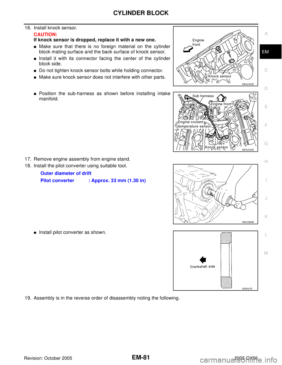
16. Install knock sensor.
CAUTION:
If knock sensor is dropped, replace it with a new one.
�Make sure that there is no foreign material on the cylinder
block mating surface and the back surface of knock sensor.
�Install it with its connector facing the center of the cylinder
block side.
�Do not tighten knock sensor bolts while holding connector.
�Make sure knock sensor does not interfere with other parts.
�Position the sub-harness as shown before installing intake
manifold.
17. Remove engine assembly from engine stand.
18. Install the pilot converter using suitable tool.
�Install pilot converter as shown.
19. Assembly is in the reverse order of disassembly noting the following.
KBIA2493E
KBIA2549E
Outer diameter of drift
Pilot converter : Approx. 33 mm (1.30 in)
PBIC0899E
SEM 53 7E
Page 2014 of 3419
EX-1
EXHAUST SYSTEM
B ENGINE
CONTENTS
C
D
E
F
G
H
I
J
K
L
M
SECTION EX
A
EX
Revision: October 20052005 QX56 PREPARATION ........................................................... 2
Special Service Tool ................................................. 2
Commercial Service Tools ........................................ 2
EXHAUST SYSTEM ................................................... 3Checking Exhaust System ........................................ 3
Removal and Installation .......................................... 3
REMOVAL ............................................................. 4
INSTALLATION ..................................................... 4
INSPECTION AFTER INSTALLATION .................. 4
Page 2016 of 3419

EXHAUST SYSTEM
EX-3
C
D
E
F
G
H
I
J
K
L
MA
EX
Revision: October 20052005 QX56
EXHAUST SYSTEMPFP:20100
Checking Exhaust SystemEBS00M3X
Check exhaust pipes, muffler and mounting for improper attachment, leaks, cracks, damage or deterioration.
�If anything is found, repair or replace damaged parts.
Removal and InstallationEBS00M3Y
Exhaust System
CAUTION:
�Be sure to use genuine exhaust system parts or equivalents which are specially designed for heat
resistance, corrosion resistance, and shape.
�Perform the operation with the exhaust system fully cooled. The system will be hot just after the
engine stops.
�Be careful not to cut your hand on the heat insulator edge.
SM A211 A
WBIA0416E
1. Tailpipe hanger bracket 2. Tailpipe 3. Gasket
4. Main muffler 5. Right front exhaust tube 6. Ring gasket
7. Heated oxygen sensor 2 (bank 2) 8. Heated oxygen sensor 2 (bank 1) 9. Left front exhaust tube
10. Center exhaust tube 11. Muffler hanger bracket front 12. Muffler hanger bracket rear
Page 2017 of 3419

EX-4Revision: October 2005
EXHAUST SYSTEM
2005 QX56
REMOVAL
Remove exhaust system components using power tool.
INSTALLATION
Installation is in the reverse order of removal.
CAUTION:
�Always replace exhaust gaskets with new ones when reassembling.
�Before installing a new heated oxygen sensor, clean and lube the exhaust tube threads using Tool.
�Discard any heated oxygen sensor which has been dropped from a height of more than 0.5 m (19.7
in) onto a hard surface such as a concrete floor; replace with a new one.
�Do not over-torque the heated oxygen sensor. Doing so may damage the heated oxygen sensor,
resulting in the MIL coming on.
�If any mounting insulator is badly deformed, repair or replace it. If deposits such as mud pile up on
the mounting insulators, clean and inspect them.
�Temporarily tighten the nuts on the exhaust manifold side and the bolts on the vehicle side. Check
each part for interference with other components, and then tighten the nuts and bolts to specifica-
tion.
INSPECTION AFTER INSTALLATION
�With the engine running, check exhaust tube joints for gas leakage and unusual noises.
�Check to ensure that mounting brackets and mounting rubbers are installed properly and free from undue
stress. Improper installation could result in excessive noise and vibration. Tool number
A : — (J-43897-18)
B : — (J-43897-12)
Page 2022 of 3419
 of each")
WHEEL HUB
FAX-5
C
E
F
G
H
I
J
K
L
MA
B
FA X
Revision: October 20052005 QX56
WHEEL HUBPFP:43202
On-Vehicle Inspection and ServiceEDS001XD
Make sure the mounting conditions (looseness, backlash) of each component and component status (wear,
damage) are normal.
WHEEL BEARING INSPECTION
�Move wheel hub in the axial direction by hand. Make sure there
is no looseness of wheel bearing.
�Rotate wheel hub and make sure there is no unusual noise or
other irregular conditions. If there are any irregular conditions,
replace wheel hub and bearing assembly.
Removal and InstallationEDS001XE
REMOVAL
1. Remove wheel and tire using power tool.
2. Remove engine under cover using power tool.
3. Without disassembling the hydraulic lines, remove caliper torque member bolts using power tool. Then
reposition brake caliper aside with wire. Refer to BR-21, "
REMOVAL" .
NOTE:
Do not press brake pedal while brake caliper is removed.Axial end play limit : 0.05 mm (0.002 in) or less
SM A57 1A
1. Disc rotor 2. Wheel hub and bearing assembly 3. Wheel stud
4. Splash guard 5. Steering knuckle
WDIA0043E
Page 2024 of 3419

DRIVE SHAFT
FAX-7
C
E
F
G
H
I
J
K
L
MA
B
FA X
Revision: October 20052005 QX56
DRIVE SHAFTPFP:39100
Removal and InstallationEDS001XF
REMOVAL
1. Remove wheel and tire using power tool.
2. Remove engine under cover using power tool.
3. Remove ABS sensor harness from mount on knuckle.
CAUTION:
Do not pull on ABS sensor harness.
4. Without disassembling the hydraulic lines, remove brake caliper using power tool. Reposition it aside with
wire. Refer to BR-21, "
Removal and Installation of Brake Caliper Assembly and Disc Rotor" .
NOTE:
Avoid depressing brake pedal while brake caliper is removed.
5. Remove coil spring and shock absorber assembly using power tool. Refer to FSU-10, "
Removal and
Installation" .
6. Separate upper link ball joint stud from steering knuckle using
Tool.
�Support lower link with jack.
7. Remove cotter pin, then remove drive shaft nut.
8. Remove drive shaft mounting bolts from front final drive.
9. Remove drive shaft from wheel hub and bearing assembly.
CAUTION:
�When removing drive shaft, do not apply an excessive
angle to drive shaft joint. Also be careful not to exces-
sively extend slide joint.
INSPECTION AFTER REMOVAL
�Move joint up, down, left, right, and in axial direction. Check for any rough movement or significant loose-
ness.
�Check boot for cracks or other damage, and for grease leakage.
�If damaged, disassemble drive shaft to verify damage, and
repair or replace as necessary.
1. Cotter pin 2. Drive shaft nut 3. Drive shaft
LDIA0159E
Tool number : ST29020001 (J-24319-01)
LEIA0095E
RAA0030D