Page 2527 of 3419

LT-80
TURN SIGNAL AND HAZARD WARNING LAMPS
Revision: October 20052005 QX56
TURN SIGNAL AND HAZARD WARNING LAMPSPFP:26120
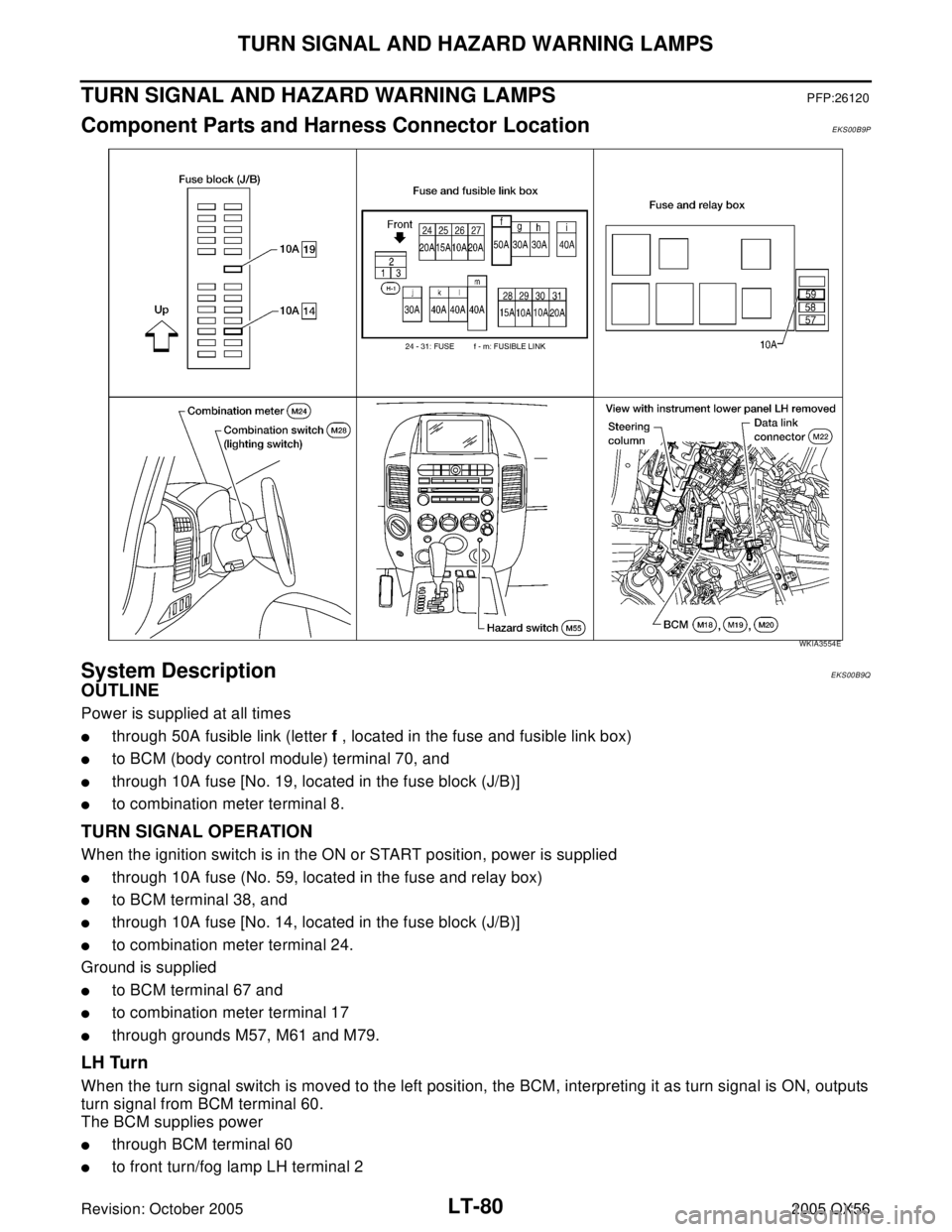
Component Parts and Harness Connector LocationEKS00B9P
System DescriptionEKS00B9Q
OUTLINE
Power is supplied at all times
�through 50A fusible link (letter f , located in the fuse and fusible link box)
�to BCM (body control module) terminal 70, and
�through 10A fuse [No. 19, located in the fuse block (J/B)]
�to combination meter terminal 8.
TURN SIGNAL OPERATION
When the ignition switch is in the ON or START position, power is supplied
�through 10A fuse (No. 59, located in the fuse and relay box)
�to BCM terminal 38, and
�through 10A fuse [No. 14, located in the fuse block (J/B)]
�to combination meter terminal 24.
Ground is supplied
�to BCM terminal 67 and
�to combination meter terminal 17
�through grounds M57, M61 and M79.
LH Turn
When the turn signal switch is moved to the left position, the BCM, interpreting it as turn signal is ON, outputs
turn signal from BCM terminal 60.
The BCM supplies power
�through BCM terminal 60
�to front turn/fog lamp LH terminal 2
WKIA3554E
Page 2528 of 3419

TURN SIGNAL AND HAZARD WARNING LAMPS
LT-81
C
D
E
F
G
H
I
J
L
MA
B
LT
Revision: October 20052005 QX56
�through front turn/fog lamp LH terminal 3
�to grounds E9, E15 and E24, and
�to rear turn signal lamp LH terminal 1
�through rear turn signal lamp LH terminal 3
�to grounds B7 and B19.
BCM sends signal to combination meter through CAN communication lines, and turns on turn signal indicator
lamp within combination meter.
RH Turn
When the turn signal switch is moved to the right position, the BCM, interpreting it as turn signal is ON, outputs
turn signal from BCM terminal 61.
The BCM supplies power
�through BCM terminal 61
�to front turn/fog lamp RH terminal 2
�through front turn/fog lamp RH terminal 3
�to grounds E9, E15 and E24, and
�to rear turn signal lamp RH terminal 1
�through rear signal lamp terminal 3
�to grounds B117 and B132.
BCM sends signal to combination meter through CAN communication lines, and turns on turn signal indicator
lamp within combination meter.
HAZARD LAMP OPERATION
Power is supplied at all times
�through 50A fusible link (letter f , located in the fuse and fusible link box)
�to BCM terminal 70, and
�through 10A fuse [No. 19, located in the fuse block (J/B)]
�to combination meter terminal 8.
Ground is supplied
�to BCM terminal 67 and
�to combination meter terminal 17
�through grounds M57, M61 and M79.
When the hazard switch is depressed, ground is supplied
�to BCM terminal 29
�through hazard switch terminal 2
�through hazard switch terminal 1
�through grounds M57, M61 and M79.
When the hazard switch is depressed, the BCM, interpreting it as hazard warning lamps are ON, outputs turn
signal from BCM terminals 60 and 61.
The BCM supplies power
�through BCM terminals 60 and 61
�to front turn/fog lamp LH and RH terminal 2
�through front turn/fog lamp LH and RH terminal 3
�to grounds E9, E15 and E24, and
�to rear turn signal lamp LH terminal 1
�through rear turn signal lamp LH terminal 3
�to grounds B7 and B19, and
�to rear turn signal lamp RH terminal 1
�through rear turn signal lamp RH terminal 3
�to grounds B117 and B132.
BCM sends signal to combination meter through CAN communication lines, and turns on turn signal indicator
lamps within combination meter.
Page 2529 of 3419

LT-82
TURN SIGNAL AND HAZARD WARNING LAMPS
Revision: October 20052005 QX56
REMOTE KEYLESS ENTRY SYSTEM OPERATION
Power is supplied at all times
�through 50A fusible link (letter f , located in the fuse and fusible link box)
�to BCM terminal 70, and
�through 10A fuse [No. 19, located in the fuse block (J/B)]
�to combination meter terminal 8.
Ground is supplied
�to BCM terminal 67 and
�to combination meter terminal 17
�through grounds M57, M61 and M79.
When the remote keyless entry system is triggered by input from the keyfob, the BCM, interpreting it as turn
signal is ON, outputs turn signal from BCM terminals 60 and 61.
The BCM supplies power
�through BCM terminals 60 and 61
�to front turn/fog lamp LH and RH terminal 2
�through front turn/fog lamp LH and RH terminal 3
�to grounds E9, E15 and E24, and
�to rear turn signal lamp LH terminal 1
�through rear turn signal lamp LH terminal 3
�to grounds B7 and B19, and
�to rear turn signal lamp RH terminal 1
�through rear turn signal lamp RH terminal 3
�to grounds B117 and B132.
BCM sends signal to combination meter through CAN communication lines, and turns on turn signal indicator
lamps within combination meter.
With power and input supplied, the BCM controls the flashing of the hazard warning lamps when keyfob is
used to activate the remote keyless entry system.
COMBINATION SWITCH READING FUNCTION
Refer to BCS-3, "COMBINATION SWITCH READING FUNCTION" .
CAN Communication System DescriptionEKS00B9R
Refer to LAN-5, "CAN COMMUNICATION" .
Page 2541 of 3419
LT-94
TURN SIGNAL AND HAZARD WARNING LAMPS
Revision: October 20052005 QX56
Bulb Replacement (Front Turn Signal Lamp)EKS00BA1
1. Remove turn/fog lamp assembly. Refer to LT- 7 9 , "Removal and Installation" .
2. Turn bulb socket counterclockwise to remove it from lamp housing.
3. Pull bulb from socket.
Installation is in the reverse order of removal.
Bulb Replacement (Rear Turn Signal Lamp)EKS00BA2
Refer to LT- 1 2 2 , "Bulb Replacement (Turn Signal)" in REAR COMBINATION LAMP.
Removal and Installation of Front Turn Signal LampEKS00BA3
Refer to LT- 3 2 , "Removal and Installation" .
Removal and Installation of Rear Turn Signal Lamp EKS00BA4
Refer to LT- 1 2 2 , "Removal and Installation" in REAR COMBINATION LAMP.
Page 2550 of 3419
STOP LAMP
LT-103
C
D
E
F
G
H
I
J
L
MA
B
LT
Revision: October 20052005 QX56
STOP LAMPPFP:26550
System DescriptionEKS00BAD
Power is supplied at all times
�through 10A fuse [No. 20, located in fuse block (J/B)]
�to stop lamp switch terminal 3, and
�to stop lamp relay terminal 1.
When the brake pedal is pressed, the stop lamp switch is closed and power is supplied
�through stop lamp switch terminal 4
�to stop lamp relay terminal 3
�through stop lamp relay terminal 4
�to rear combination lamp LH and RH terminal 2, and
�to high-mounted stop lamp terminal +.
Ground is supplied
�to rear combination lamp LH terminal 1, and
�to high-mounted stop lamp terminal –
�through grounds B7 and B19, and
�to rear combination lamp RH terminal 1
�through grounds B117 and B132.
With power and ground supplied, the stop lamps illuminate.
Page 2554 of 3419
BACK-UP LAMP
LT-107
C
D
E
F
G
H
I
J
L
MA
B
LT
Revision: October 20052005 QX56
Bulb ReplacementEKS00BAI
1. Remove back door lower finisher. Refer to EI-42, "Removal and Installation" .
2. Turn bulb socket counterclockwise and remove it from the lamp housing.
3. Pull bulb from socket.
Installation is in the reverse order of removal.
Removal and InstallationEKS00BAJ
1. Remove license lamp finisher. Refer to EI-24, "Removal and Installation" .
2. Carefully release tabs to remove back up lamp housing from
license plate finisher.
Installation is in the reverse order of removal.
WKIA1898E
Page 2568 of 3419
PARKING, LICENSE PLATE AND TAIL LAMPS
LT-121
C
D
E
F
G
H
I
J
L
MA
B
LT
Revision: October 20052005 QX56
Front Parking LampEKS00BAW
BULB REPLACEMENT
For bulb replacement, refer to LT-31, "FRONT PARKING LAMP (INNER OR OUTER)" or LT-31, "FRONT
SIDE MARKER LAMP" .
Tail LampEKS00BAX
BULB REPLACEMENT
The tail lamp bulbs are not serviceable separately. Replace rear combination lamp. Refer to LT-122, "Removal
and Installation" .
License Plate LampEKS00BAY
BULB REPLACEMENT
1. Remove back door lower finisher. Refer to EI-42, "Removal and Installation" .
2. Turn bulb socket counterclockwise to remove it.
3. Pull bulb from socket.
Installation is in the reverse order of removal.
Page 2569 of 3419
LT-122
REAR COMBINATION LAMP
Revision: October 20052005 QX56
REAR COMBINATION LAMPPFP:26554
Bulb Replacement (Turn Signal)EKS00BAZ
NOTE:
The tail/stop lamp bulbs are LEDs and are not serviceable separately.
1. Remove rear combination lamp mounting bolts.
2. Pull rear combination lamp to remove from the vehicle.
3. Turn bulb socket counterclockwise and unlock it.
4. Remove bulb.
Installation is in the reverse order of removal.
Removal and InstallationEKS00BB0
1. Remove rear combination lamp mounting bolts.
2. Pull rear combination lamp to remove from the vehicle.
3. Disconnect rear combination lamp connectors.
Installation is in the reverse order of removal.
WKIA1393E
Rear combination lamp
mounting bolts: 2.4 Nm (0.24 kg-m, 21 in-lb)
WKIA1393E