Page 2961 of 3419
 with the ign")
SC-24
CHARGING SYSTEM
Revision: October 20052005 QX56
2. CHECK CHARGE WARNING LAMP CIRCUIT
1. Disconnect E205 connector from generator.
2. Apply ground to connector E205 terminal 3 (BR/W) with the igni-
tion switch in the ON position.
OK or NG
OK >> Replace the generator. Refer to SC-27, "Removal and
Installation" . Confirm repair by performing complete
battery/starting/charging system test.
NG >> Check the following.
�10A fuse [No. 14, located in fuse block (J/B)]
�Charge warning lamp
�Harness for open or short between combination meter and fuse
�Harness for open or short between combination meter and generator
DIAGNOSTIC PROCEDURE 4
Check Battery Circuit
1. CHECK BATTERY CIRCUIT CONNECTION
1. Turn the ignition switch OFF.
2. Check to see if terminal 1 is clean and tight.
OK or NG
OK >> GO TO 2.
NG >> Repair terminal 1 connection. Confirm repair by performing complete Battery/Starting/Charging
system test.
2. CHECK BATTERY CIRCUIT
Check voltage between generator connector E206 terminal 1 (B/R)
and ground using a digital circuit tester.
OK or NG
OK >> GO TO 3.
NG >> Check the following.
�140A fusible link (letter a , located in fusible link box)
�Harness for open or short between generator and fus-
ible link
3. CHECK VOLTAGE DROP ON BATTERY CIRCUIT
1. Start the engine.
2. Check voltage between generator connector E206 terminal 1 (B/
R) and battery positive terminal using a digital circuit tester.
OK or NG
OK >> GO TO 4.
NG >> Check harness between the battery and the generator
for poor continuity. Charge warning lamp should
light up.
WKIA2110E
Battery voltage should exist.
W K I A 2111 E
With engine running
at idle and warm.: Less than 0.2V
WKIA2112E
Page 2962 of 3419
CHARGING SYSTEM
SC-25
C
D
E
F
G
H
I
J
L
MA
B
SC
Revision: October 20052005 QX56
4. CHECK GENERATOR DRIVE BELT TENSION
1. Turn the ignition switch OFF.
2. Check generator drive belt tension. Refer to EM-12, "
DRIVE BELTS" .
OK or NG
OK >> Replace the generator. Refer to SC-27, "Removal and Installation" . Confirm repair by performing
complete battery/starting/charging system test.
NG >> Readjust drive belt tension. Refer to EM-12, "
Tension Adjustment" .
Page 2963 of 3419

SC-26
CHARGING SYSTEM
Revision: October 20052005 QX56
DIAGNOSTIC PROCEDURE 5
Check Voltage Regulator Circuit
1. CHECK VOLTAGE REGULATOR CIRCUIT CONNECTION
1. Turn the ignition switch OFF.
2. Check to see if terminal 4 is clean and tight.
OK or NG
OK >> GO TO 2.
NG >> Repair terminal 4 connection. Confirm repair by performing complete Battery/Starting/Charging
system test.
2. CHECK VOLTAGE REGULATOR CIRCUIT
Check voltage between generator connector E205 terminal 4 (Y/B)
and ground using a digital circuit tester.
OK or NG
OK >> GO TO 3.
NG >> Check the following.
�10A fuse (No. 30, located in fuse and fusible link box)
�Harness for open or short between generator and
fuse
3. CHECK VOLTAGE DROP ON VOLTAGE REGULATOR CIRCUIT
1. Start the engine.
2. Check voltage between generator connector E205 terminal 4 (Y/
B) and battery positive terminal using a digital circuit tester.
OK or NG
OK >> Replace the generator. Refer to SC-27, "Removal and
Installation" . Confirm repair by performing complete
Battery/Starting/Charging system test.
NG >> Check harness between the battery and the generator
for poor continuity. Battery voltage should exist.
WKIA2113E
With engine running
at idle and warm.: Less than 0.2V
WKIA2114E
Page 2977 of 3419
 and door mirror posit")
SE-12
AUTOMATIC DRIVE POSITIONER
Revision: October 20052005 QX56
Manual OperationEIS004XC
The driving position [seat position, steering wheel, pedal position (accelerator, brake) and door mirror position]
can be adjusted with the power seat switch LH, pedal adjusting switch, door mirror remote control switch or
ADP steering switch.
NOTE:
�The door mirrors can be manually operated with the ignition switch turned to ACC or ON.
�Adjustable pedals can only operate when A/T shift lever is in P position (except when ignition switch
turned to OFF).
�If A/T device (detent switch) error is detected, manual adjustable pedal operation cannot be performed
when ignition switch turns ON.
Automatic OperationEIS004XD
NOTE:
�Disconnecting the battery erases the stored memory.
�After connecting the battery, insert the key into the ignition cylinder and turn the front door switch LH ON (open)→OFF (close)→ON
(open), the Entry/ Exiting function becomes possible.
�After Exiting operation is carried out, return operation can be operated.
NOTE:
During automatic operation, if the ignition switch is turned ON→START, the automatic operation is suspended. When the ignition switch
returns to ON, it resumes.
System DescriptionEIS004XE
�The system automatically moves the driver seat and steering wheel to facilitate entry/exit to/from the vehi-
cle. The driver seat control unit can also store the optimum driving positions (driver seat, steering wheel,
pedal position and door mirror position) for 2 people. One-touch operation allows changing between driv-
ing positions.
7. Pedal adjusting switch M96 8. A. Door mirrror LH D4, RH D107
B. Front door switch LH B8
C. Front door lock assembly LH (key
cylinder switch) D149. A. A/T selector lever
B. A/T device (detent switch) M203
10. A. Sliding motor LH P4 (driver seat
view), reclining motor LH P5, lifting
motor (front) P6, lifting motor (rear)
P7
B. Driver seat control unit P2, P3
C. Power seat switch LH P811. A. ADP steering switch M16
B.Tilt motor M68, M69
Function Description
Memory operation The seat, steering wheel, pedals (accelerator, brake) and door mirrors move to the
stored driving position by pushing seat memory switch (1 or 2).
Entry/Exit-
ing functionExiting operation At exit, the seat moves backward and the steering wheel raises. (Exiting position)
Entry operationAt entry, the seat and steering wheel return from Exiting position to the previous driv-
ing position before the Exiting operation.
Keyfob interlock operationPerform memory operation, turnout operation and return operation by pressing key-
fob unlock button.
Auto operation temporary stop
conditions.When ignition switch is turned to START during seat memory switch operation and return
operation, seat memory switch operation and return operation is stopped.
Auto operation stop conditions.
�When the vehicle speed becomes 7 km/h (4 MPH) or higher (memory switch operation
and entry operation).
�When the setting switch, seat memory switch 1, or 2 are pressed.
�When A/T shift lever is in any position other than P.
�When the door mirror remote control switch is operated (when ignition switch turned to
ON).
�When power seat switch turned ON.
�When pedal adjusting switch turned ON.
�When front seat sliding Entry/Exiting setting is OFF (entry/exiting operation).
Page 2982 of 3419
AUTOMATIC DRIVE POSITIONER
SE-17
C
D
E
F
G
H
J
K
L
MA
B
SE
Revision: October 20052005 QX56
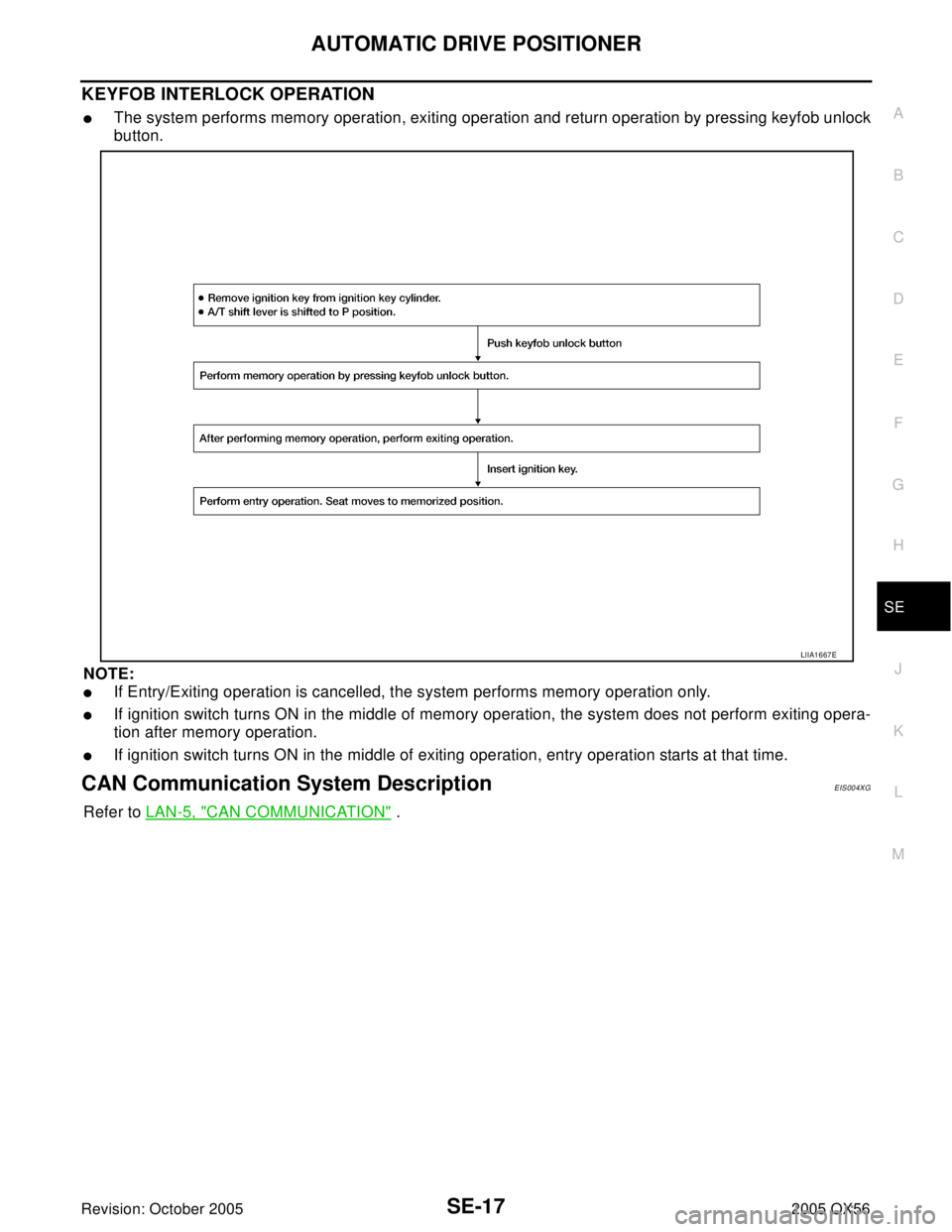
KEYFOB INTERLOCK OPERATION
�The system performs memory operation, exiting operation and return operation by pressing keyfob unlock
button.
NOTE:
�If Entry/Exiting operation is cancelled, the system performs memory operation only.
�If ignition switch turns ON in the middle of memory operation, the system does not perform exiting opera-
tion after memory operation.
�If ignition switch turns ON in the middle of exiting operation, entry operation starts at that time.
CAN Communication System DescriptionEIS004XG
Refer to LAN-5, "CAN COMMUNICATION" .
LIIA1667E
Page 2995 of 3419

SE-30
AUTOMATIC DRIVE POSITIONER
Revision: October 20052005 QX56
Terminals and Reference Values for BCMEIS004XJ
Terminals and Reference Values for Driver Seat Control UnitEIS004XK
TERMINAL WIRE
COLORITEM CONDITIONVOLTAGE (V)
(Approx.)
11 O Ignition switch (ACC or ON) Ignition switch (ACC or ON position) Battery voltage
38 W/L Ignition switch (ON or START)Ignition switch (ON or START posi-
tion)Battery voltage
39 L CAN-H — —
40 P CAN-L — —
47 SB Front door switch LH ON (Open) → OFF (Closed) 0 → Battery voltage
67 B Ground — 0
70 W/B Battery power supply — Battery voltage
TERMINALWIRE
COLORITEM CONDITIONVOLTAGE (V)
(Approx.)
1LUART LINE (RX)Pedal adjusting switch ON (FOR-
WARD or BACKWARD operation)
3 L CAN-H — —
6 O Ignition switch (START) Ignition switch (START position) Battery voltage
9 L/R Reclining motor sensor signalON (seat reclining motor opera-
tion)
Other than above 0 or 5
10 W Rear lifting motor sensor signalON (rear lifting motor operation)
Other than above 0 or 5
11 R / BSliding switch BACKWARD sig-
nalON (seat sliding switch BACK-
WARD operation)0
Other than above Battery voltage
12 O/BReclining switch BACKWARD
signalON (seat reclining switch BACK-
WARD operation)0
Other than above Battery voltage
13 L/B Front lifting switch DOWN signalON (front lifting switch DOWN
operation)0
Other than above Battery voltage
PIIA4813E
SIIA0692J
SIIA0693J
Page 2996 of 3419
0
Other than above Battery volt")
AUTOMATIC DRIVE POSITIONER
SE-31
C
D
E
F
G
H
J
K
L
MA
B
SE
Revision: October 20052005 QX56
14 G/W Rear lifting switch DOWN signalON (rear lifting switch DOWN
operation)0
Other than above Battery voltage
15 L/YPedal adjusting switch BACK-
WARD signalON (pedal adjusting switch BACK-
WARD operation) 0
Other than above Battery voltage
16 W Seat sensor power Ignition switch ON 5
17 W UART LINE (TX)Pedal adjusting switch ON (FOR-
WARD or BACKWARD operation)
19 P CAN-L — —
21 L/R A/T device (detent switch) signalSelector lever in P position 0
Selector lever other than P posi-
tion with ignition key in ignition cyl-
inderBattery voltage
24 Y/G Seat sliding motor sensor signalON (seat sliding motor operation)
Other than above 0 or 5
25 LG Front lifting motor sensor signalON (front lifting motor operation)
Other than above. 0 or 5
26 P/BSeat sliding switch FORWARD
signalON (seat sliding switch FOR-
WARD operation)0
Other than above Battery voltage
27 G/BSeat reclining switch FOR-
WARD signalON (seat reclining switch FOR-
WARD operation)0
Other than above Battery voltage
28 Y/B Front lifting switch UP signalON (front lifting switch UP opera-
tion)0
Other than above Battery voltage
29 R/W Rear lifting switch UP signalON (rear lifting switch UP opera-
tion)0
Other than above Battery voltage
30 RPedal adjusting switch FOR-
WARD signalON (pedal adjusting switch FOR-
WARD operation)0
Other than above Battery voltage TERMINALWIRE
COLORITEM CONDITIONVOLTAGE (V)
(Approx.)
PIIA4814E
PIIA3277E
SIIA0691J
Page 3001 of 3419

SE-36
AUTOMATIC DRIVE POSITIONER
Revision: October 20052005 QX56
2. CHECK BCM POWER SUPPLY CIRCUIT
1. Disconnect BCM.
2. Check voltage between BCM connector and ground.
OK or NG
OK >> GO TO 3.
NG >> Repair or replace harness.
3. CHECK BCM GROUND CIRCUIT
1. Turn ignition switch OFF.
2. Check continuity between BCM connector M20 terminal 67 (B) and ground.
OK or NG
OK >> BCM circuit is OK. Check the driver seat control unit.
GO TO 4.
NG >> Repair or replace harness.
4. CHECK DRIVER SEAT CONTROL UNIT FUSES AND FUSIBLE LINK
Make sure any of the following fuses in the driver seat control unit and automatic drive positioner control unit
are not blown.
NOTE:
Refer to SE-11, "
Component Parts And Harness Connector Location" .
OK or NG
OK >> GO TO 5.
NG >> If fuse is blown, be sure to eliminate cause of malfunction before installing new fuse. Refer to PG-
63, "ELECTRICAL UNITS LOCATION" .
ConnectorTerminals
(Wire color)Power
sourceConditionVoltage (V)
(Approx.)
(+) (–)
M20 70 (W/B) GroundBattery
power
supplyIgnition
switch
OFFBattery voltage
M1838 (W/L) GroundIgnition
power
supplyIgnition
switch
ON or
STARTBattery voltage
11 (O) GroundACC or
ON
power
supplyIgnition
switch
ACC or
ONBattery voltage
LIIA0995E
67 (B) - Ground : Continuity should exist.
LIIA0915E
Unit Power source Fuse No.
Driver seat control unitSTART power supply 2 (10A)
Battery power supply 22 (15A)
Battery power supplyf (50A)