Page 2780 of 3419
STEERING COLUMN
PS-13
C
D
E
F
H
I
J
K
L
MA
B
PS
Revision: October 20052005 QX56
Disassembly and AssemblyEGS000UG
DISASSEMBLY
1. Remove mounting bolt from upper joint, then remove upper joint from steering column assembly.
2. Remove ignition switch tamper resistant self-shear screws with a drill or other suitable tool.
1. Steering column assembly 2. Upper joint 3. Ignition switch
4. Tamper resistant self-shear screw
WGIA0091E
Page 2827 of 3419
RF-10
SUNROOF
Revision: October 20052005 QX56
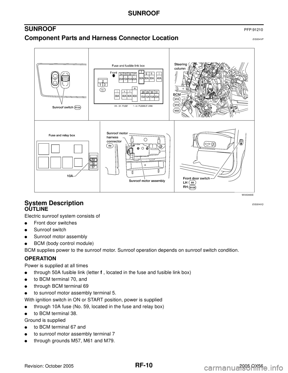
SUNROOFPFP:91210
Component Parts and Harness Connector LocationEIS004VP
System DescriptionEIS004VQ
OUTLINE
Electric sunroof system consists of
�Front door switches
�Sunroof switch
�Sunroof motor assembly
�BCM (body control module)
BCM supplies power to the sunroof motor. Sunroof operation depends on sunroof switch condition.
OPERATION
Power is supplied at all times
�through 50A fusible link (letter f , located in the fuse and fusible link box)
�to BCM terminal 70, and
�through BCM terminal 69
�to sunroof motor assembly terminal 5.
With ignition switch in ON or START position, power is supplied
�through 10A fuse (No. 59, located in the fuse and relay box)
�to BCM terminal 38.
Ground is supplied
�to BCM terminal 67 and
�to sunroof motor assembly terminal 7
�through grounds M57, M61 and M79.
WIIA0465E
Page 2828 of 3419

SUNROOF
RF-11
C
D
E
F
G
H
J
K
L
MA
B
RF
Revision: October 20052005 QX56
TILT UP OPERATION
When the tilt switch is operated for tilt up, ground is supplied
�to sunroof motor assembly terminal 4
�through sunroof switch terminal 4
�through sunroof switch terminal 2
�through sunroof motor assembly terminal 8
�through grounds M57, M61 and M79.
Then, the sunroof will tilt up.
TILT DOWN OPERATION
When the tilt switch is operated for tilt down, ground is supplied
�to sunroof motor assembly terminal 10
�through sunroof switch terminal 6
�through sunroof switch terminal 2
�through sunroof motor assembly terminal 8
�through grounds M57, M61 and M79.
Then, the sunroof will tilt down.
SLIDE OPEN OPERATION
When the switch is operated for slide open, ground is supplied
�to sunroof motor assembly terminal 9
�through sunroof switch terminal 3
�through sunroof switch terminal 2
�through sunroof motor assembly terminal 8
�through grounds M57, M61 and M79.
Then, the sunroof will slide open.
SLIDE CLOSE OPERATION
When the switch is operated for slide close, ground is supplied
�to sunroof motor assembly terminal 3
�through sunroof switch terminal 1
�through sunroof switch terminal 2
�through sunroof motor assembly terminal 8
�through grounds M57, M61 and M79.
Then, the sunroof will slide closed.
RETAINED POWER OPERATION
When the ignition switch is turned to OFF position from ON or START position, power is supplied for 45 sec-
onds.
The retained power operation is canceled when the driver or passenger side door is opened.
RAP signal period can be changed by CONSULT-II. Refer to RF-16, "
CONSULT-II Function (BCM)" .
MEMORY RESET PROCEDURE
If the battery is disconnected, or the sunroof motor harness connector is disconnected, the slide switch will
become inoperable and the sunroof motor memory must be reset. To reset the sunroof motor memory from
any sunroof position (full open, partially open, closed, partially vented, and vented), push and hold the sunroof
tilt switch in the forward (DOWN) position until the sunroof is fully closed. After it has closed all the way, push
and hold the tilt switch forward (DOWN) for more than 2 seconds to re-establish the motor preset position. The
sunroof should now operate normally.
INTERRUPTION DETECTION FUNCTION
The CPU (central processing unit) monitors the sunroof motor operation and the sunroof position (fully-closed
or other) by the signals from the sunroof motor.
When sunroof motor detects an interruption during the following sliding close operations, sunroof switch con-
trols the motor for open and the sunroof will operate until it reaches full open position.
Page 2829 of 3419
RF-12
SUNROOF
Revision: October 20052005 QX56
�automatic close operation when ignition switch is in the ON position.
�automatic close operation during retained power operation.
CAN Communication System DescriptionEIS004VR
Refer to LAN-5, "CAN COMMUNICATION" .
Page 2832 of 3419

SUNROOF
RF-15
C
D
E
F
G
H
J
K
L
MA
B
RF
Revision: October 20052005 QX56
Terminals and Reference Values for BCMEIS004VT
Terminals and Reference Values for Sunroof Motor AssemblyEIS004VU
Work FlowEIS004VV
1. Check the symptom and customer's requests.
2. Understand the outline of system. Refer to RF-10, "
System Description" .
3. According to the trouble diagnosis chart, repair or replace the cause of the malfunction.
Refer to RF-17, "
Trouble Diagnosis Chart by Symptom" .
4. Does sunroof system operate normally? If Yes, GO TO 5, If No, GO TO 3.
5. Inspection End.
Terminal Wire Color Item ConditionVoltage
(Approx.)
12 R/L Front door switch RH signalON (Open) 0
OFF (Close) Battery voltage
38 W/L Ignition power supply Ignition switch ON Battery voltage
47 SB Front door switch LH signalON (Open) 0
OFF (Close) Battery voltage
67 B Ground — —
68 W/L RAP signalIgnition switch ON Battery voltage
Within 45 second after ignition switch is turned
OFF Battery voltage
When front door LH or RH is open while
retained power is operating0
69 W/R Power window power supply — Battery voltage
70 W/B BAT power supply — Battery voltage
Terminal Wire Color Item ConditionVo ltag e
(Approx.)
1 W/L RAP signalIgnition switch ON Battery voltage
Within 45 second after ignition switch is
turned OFFBattery voltage
When front door LH or RH is open while
retained power is operating0
3 P/W Sunroof switch CLOSE signalIgnition switch ON and sunroof switch
CLOSE position0
Other than above Battery voltage
4 O Sunroof switch TILT UP signalIgnition switch ON and sunroof switch in
TILT UP position0
Other than above Battery voltage
5 W/R BAT power supply — Battery voltage
7 B Ground — —
8 Y Ground signal — —
9 P Sunroof switch OPEN signalIgnition switch ON and sunroof switch
OPEN position0
Other than above Battery voltage
10 L/R Sunroof switch TILT DOWN signalIgnition switch ON and sunroof switch in
TILT DOWN position0
Other than above Battery voltage
Page 2833 of 3419
EIS004VW
CONSULT-II can display each diagnostic item using the diagnostic test modes shown following.
CONSULT-II OPERATION
CAUTIO")
RF-16
SUNROOF
Revision: October 20052005 QX56
CONSULT-II Function (BCM)EIS004VW
CONSULT-II can display each diagnostic item using the diagnostic test modes shown following.
CONSULT-II OPERATION
CAUTION:
If CONSULT-II is used with no connection of CONSULT-II CONVERTER, malfunctions might be
detected in self-diagnosis depending on control unit which carries out CAN communication.
1. With the ignition switch OFF, connect CONSULT-II and CON-
SULT-II CONVERTER to the data link connector, then turn igni-
tion switch ON.
2. Touch "START (NISSAN BASED VHCL)".
3. Touch "BCM".
If "BCM" is not indicated, go to GI-39, "
CONSULT-II Data Link
Connector (DLC) Circuit" .
BCM diagnostic
test itemDiagnostic mode Description
Inspection by partWORK SUPPORTSupports inspections and adjustments. Commands are transmitted to the BCM
for setting the status suitable for required operation, input/output signals are
received from the BCM and received data is displayed.
DATA MONITOR Displays BCM input/output data in real time.
ACTIVE TEST Operation of electrical loads can be checked by sending drive signal to them.
SELF-DIAG RESULTS Displays BCM self-diagnosis results.
CAN DIAG SUPPORT MNTR The result of transmit/receive diagnosis of CAN communication can be read.
ECU PART NUMBER BCM part number can be read.
CONFIGURATION Performs BCM configuration read/write functions.
BBIA0369E
BCIA0029E
BCIA0030E
Page 2834 of 3419

SUNROOF
RF-17
C
D
E
F
G
H
J
K
L
MA
B
RF
Revision: October 20052005 QX56
4. Touch "RETAINED PWR".
5. Select diagnosis mode. "DATA MONITOR", "ACTIVE TEST" and
"WORK SUPPORT" are available.
Work Support EIS004VZ
Active TestEIS004VY
Data MonitorEIS004VX
Trouble Diagnosis Chart by SymptomEIS004W0
LIIA0163E
BCIA0031E
Work item Description
RETAINED PWR SETRAP signal’s power supply period can be changed by mode setting. Selects RAP sig-
nal’s power supply period between two steps.
�MODE 1 (45 sec.) / MODE 2 (OFF) / MODE 3 (2 min.)
Test item Description
RETAINED PWRThis test is able to supply RAP signal (power) from BCM to power window system,
power sunroof system. Those systems can be operated when turning on "RETAINED
PWR" on CONSULT-II screen even if the ignition switch is turned OFF.
NOTE:
During this test, CONSULT-II can be operated with ignition switch in "OFF"
position. "RETAINED PWR" should be turned "ON" or "OFF" on CONSULT-II
screen when ignition switch ON. Then turn ignition switch OFF for checking
retained power operation. CONSULT-II might be stuck if "RETAINED PWR" is
turned "ON" or "OFF" on CONSULT-II screen when ignition switch is OFF.
Monitored item Description
IGN ON SW Indicates [ON/OFF] condition of ignition switch.
DOOR SW-DR Indicates [ON/OFF] condition of front door switch driver side.
DOOR SW-AS Indicates [ON/OFF] condition of front door switch passenger side.
Symptom Diagnostic procedure and repair order Refer to page
Sunroof does not operate.1. Sunroof motor assembly power supply and ground
circuit checkRF-20
2. Sunroof switch system checkRF-19
3. BCM power supply and ground circuit checkRF-18
4. Replace sunroof motor assemblyRF-27
Page 2835 of 3419

RF-18
SUNROOF
Revision: October 20052005 QX56
BCM Power Supply and Ground Circuit CheckEIS004W1
1. CHECK FUSE
Check the following BCM fuse and fusible link.
NOTE:
Refer to RF-10, "
Component Parts and Harness Connector Location" .
OK or NG
OK >> GO TO 2.
NG >> If fuse is blown, be sure to eliminate cause of blown fuse before installing new fuse. Refer to PG-
4, "POWER SUPPLY ROUTING CIRCUIT" .
2. CHECK POWER SUPPLY CIRCUIT
1. Turn ignition switch OFF.
2. Disconnect BCM connectors.
3. Check voltage between BCM connectors M18 and M20 termi-
nals 38, 70 and ground.
OK or NG
OK >> GO TO 3.
NG >> Repair or replace harness.
3. CHECK GROUND CIRCUIT
Check continuity between BCM connector M20 terminal 67 and
ground.
OK or NG
OK >> Power supply and ground circuit is OK.
NG >> Repair or replace harness.
Retained power operation does not operate properly.1. Check the retained power operation mode settingRF-112. BCM power supply and ground circuit checkRF-18
3. Door switch checkRF-21
4. Replace sunroof motor assemblyRF-27
Motor does not stop at the sunroof fully-open or fully-
closed position.1. Initialization procedure checkRF-11
2. Replace sunroof motor assemblyRF-27
Sunroof does not do the interruption detection. 1. Replace sunroof motor assemblyRF-27
Symptom Diagnostic procedure and repair order Refer to page
Component Parts Terminal No. (SIGNAL) Ampere No. Location
BCM38 (IGN power supply) 10A 59 Fuse and relay box
70 (BAT power supply) 50A f Fuse and fusible link box
ConnectorTerminals
(Wire color)
ConditionVo l ta g e
(Approx.)
(+) (–)
M18 38 (W/L)
GroundIgnition switch ON
Battery voltage
M20 70 (W/B) Igniting switch OFF
WIIA0229E
Connector Terminals (Wire color) Continuity
M20 67 (B) Ground YES
LIIA0915E