Page 2646 of 3419

ENGINE MAINTENANCE
MA-13
C
D
E
F
G
H
I
J
K
MA
B
MA
Revision: October 20052005 QX56
ENGINE MAINTENANCEPFP:00000
Checking Drive BeltsELS001BP
WA RN ING:
Be sure to perform when the engine is stopped.
1. Remove air duct and resonator assembly (inlet) when inspecting drive belt.
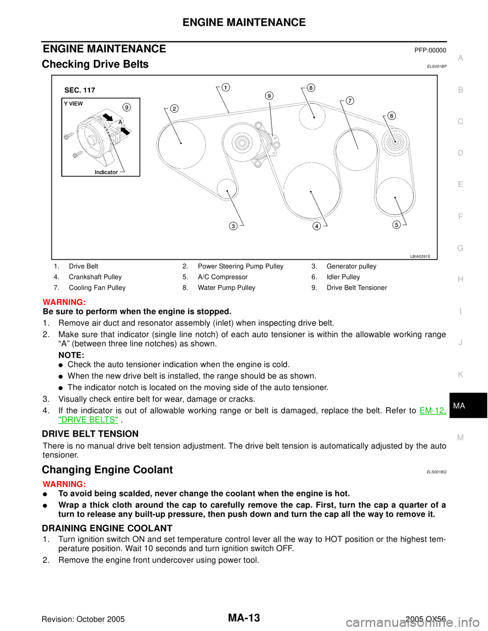
2. Make sure that indicator (single line notch) of each auto tensioner is within the allowable working range
“A” (between three line notches) as shown.
NOTE:
�Check the auto tensioner indication when the engine is cold.
�When the new drive belt is installed, the range should be as shown.
�The indicator notch is located on the moving side of the auto tensioner.
3. Visually check entire belt for wear, damage or cracks.
4. If the indicator is out of allowable working range or belt is damaged, replace the belt. Refer to EM-12,
"DRIVE BELTS" .
DRIVE BELT TENSION
There is no manual drive belt tension adjustment. The drive belt tension is automatically adjusted by the auto
tensioner.
Changing Engine CoolantELS001BQ
WA RN ING:
�To avoid being scalded, never change the coolant when the engine is hot.
�Wrap a thick cloth around the cap to carefully remove the cap. First, turn the cap a quarter of a
turn to release any built-up pressure, then push down and turn the cap all the way to remove it.
DRAINING ENGINE COOLANT
1. Turn ignition switch ON and set temperature control lever all the way to HOT position or the highest tem-
perature position. Wait 10 seconds and turn ignition switch OFF.
2. Remove the engine front undercover using power tool.
1. Drive Belt 2. Power Steering Pump Pulley 3. Generator pulley
4. Crankshaft Pulley 5. A/C Compressor 6. Idler Pulley
7. Cooling Fan Pulley 8. Water Pump Pulley 9. Drive Belt Tensioner
LBIA0391E
Page 2647 of 3419

MA-14
ENGINE MAINTENANCE
Revision: October 20052005 QX56
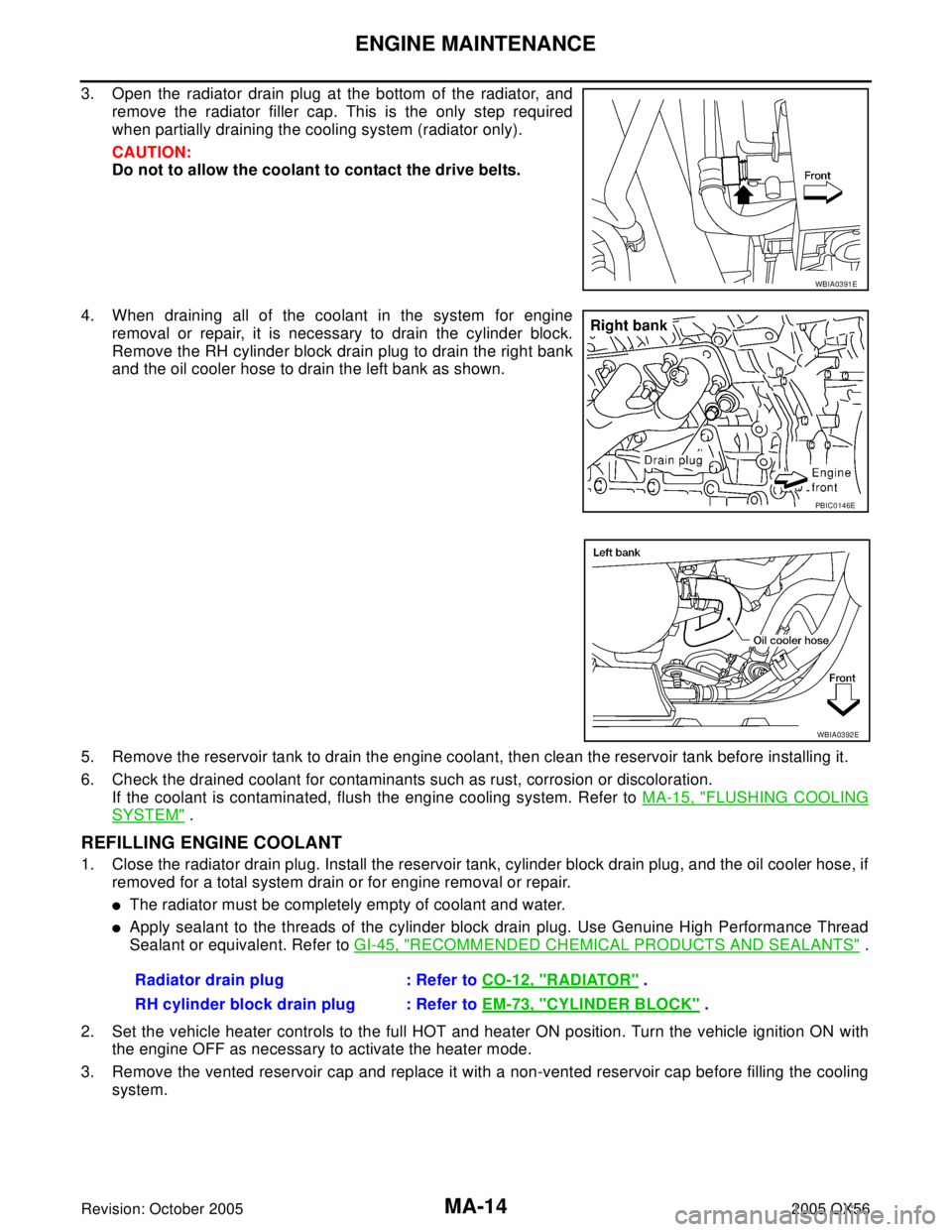
3. Open the radiator drain plug at the bottom of the radiator, and
remove the radiator filler cap. This is the only step required
when partially draining the cooling system (radiator only).
CAUTION:
Do not to allow the coolant to contact the drive belts.
4. When draining all of the coolant in the system for engine
removal or repair, it is necessary to drain the cylinder block.
Remove the RH cylinder block drain plug to drain the right bank
and the oil cooler hose to drain the left bank as shown.
5. Remove the reservoir tank to drain the engine coolant, then clean the reservoir tank before installing it.
6. Check the drained coolant for contaminants such as rust, corrosion or discoloration.
If the coolant is contaminated, flush the engine cooling system. Refer to MA-15, "
FLUSHING COOLING
SYSTEM" .
REFILLING ENGINE COOLANT
1. Close the radiator drain plug. Install the reservoir tank, cylinder block drain plug, and the oil cooler hose, if
removed for a total system drain or for engine removal or repair.
�The radiator must be completely empty of coolant and water.
�Apply sealant to the threads of the cylinder block drain plug. Use Genuine High Performance Thread
Sealant or equivalent. Refer to GI-45, "
RECOMMENDED CHEMICAL PRODUCTS AND SEALANTS" .
2. Set the vehicle heater controls to the full HOT and heater ON position. Turn the vehicle ignition ON with
the engine OFF as necessary to activate the heater mode.
3. Remove the vented reservoir cap and replace it with a non-vented reservoir cap before filling the cooling
system.
WBIA0391E
PBIC0146E
WBIA0392E
Radiator drain plug : Refer to CO-12, "RADIATOR" .
RH cylinder block drain plug : Refer to EM-73, "
CYLINDER BLOCK" .
Page 2651 of 3419
MA-18
ENGINE MAINTENANCE
Revision: October 20052005 QX56
2. Apply engine oil to the oil seal circumference of the new oil filter.
3. Screw the oil filter manually until it touches the installation sur-
face, then tighten it by 2/3 turn. Or tighten to specification.
4. Inspect the engine for oil leakage.
5. Install the engine front undercover using power tool.
INSPECTION AFTER INSTALLATION
1. Check the engine oil level.
2. Start the engine and check for engine oil leakage.
3. Stop engine and wait for 10 minutes.
4. Check the engine oil level and add engine oil as required.
Changing Spark PlugsELS001BW
SM A01 0
Oil filter : 17.7 N·m (1.8 kg-m, 13 ft-lb)
SM A22 9B
SM A95 4C
1. Ignition coil 2. Spark plug
KBIA2505E
Page 2652 of 3419

ENGINE MAINTENANCE
MA-19
C
D
E
F
G
H
I
J
K
MA
B
MA
Revision: October 20052005 QX56
REMOVAL
1. Disconnect the harness connector from the ignition coil.
2. Remove the ignition coil. Refer to EM-26, "
IGNITION COIL" .
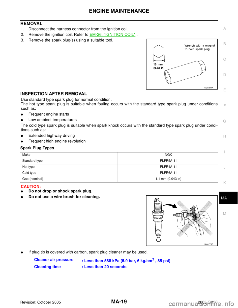
3. Remove the spark plug(s) using a suitable tool.
INSPECTION AFTER REMOVAL
Use standard type spark plug for normal condition.
The hot type spark plug is suitable when fouling occurs with the standard type spark plug under conditions
such as:
�Frequent engine starts
�Low ambient temperatures
The cold type spark plug is suitable when spark knock occurs with the standard type spark plug under condi-
tions such as:
�Extended highway driving
�Frequent high engine revolution
Spark Plug Types
CAUTION:
�Do not drop or shock spark plug.
�Do not use a wire brush for cleaning.
�If plug tip is covered with carbon, spark plug cleaner may be used.
SEM 29 4A
MakeNGK
Standard typePLFR5A-11
Hot typePLFR4A-11
Cold typePLFR6A-11
Gap (nominal)1.1 mm (0.043 in)
SM A77 3C
Cleaner air pressure
: Less than 588 kPa (5.9 bar, 6 kg/cm2 , 85 psi)
Cleaning time : Less than 20 seconds
Page 2676 of 3419

PG-1
POWER SUPPLY, GROUND & CIRCUIT ELEMENTS
K ELECTRICAL
CONTENTS
C
D
E
F
G
H
I
J
L
M
SECTION PG
A
B
PG
Revision: October 20052005 QX56 PRECAUTIONS .......................................................... 3
Precautions for Supplemental Restraint System
(SRS) “AIR BAG” and “SEAT BELT PRE-TEN-
SIONER” .................................................................. 3
Wiring Diagrams and Trouble Diagnosis .................. 3
POWER SUPPLY ROUTING CIRCUIT ...................... 4
Schematic ................................................................ 4
Wiring Diagram — POWER — ................................. 6
BATTERY POWER SUPPLY — IGNITION SW.
IN ANY POSITION ................................................ 6
ACCESSORY POWER SUPPLY — IGNITION
SW. IN ACC OR ON .............................................11
IGNITION POWER SUPPLY — IGNITION SW.
IN ON .................................................................. 12
IGNITION POWER SUPPLY — IGNITION SW.
IN ON AND/OR START ....................................... 13
IPDM E/R (INTELLIGENT POWER DISTRIBUTION
MODULE ENGINE ROOM) ...................................... 17
System Description ................................................ 17
SYSTEMS CONTROLLED BY IPDM E/R ........... 17
CAN COMMUNICATION LINE CONTROL ......... 17
IPDM E/R STATUS CONTROL ........................... 18
CAN Communication System Description .............. 18
Function of Detecting Ignition Relay Malfunction ... 18
CONSULT-II Function IPDM E/R ............................ 19
CONSULT-II BASIC OPERATION ...................... 19
SELF-DIAGNOSTIC RESULTS .......................... 20
DATA MONITOR ................................................. 20
ACTIVE TEST ..................................................... 21
Auto Active Test ..................................................... 22
DESCRIPTION .................................................... 22
OPERATION PROCEDURE ............................... 22
INSPECTION IN AUTO ACTIVE TEST MODE ... 22
Schematic .............................................................. 24
IPDM E/R Terminal Arrangement ........................... 25
IPDM E/R Power/Ground Circuit Inspection .......... 26
Inspection with CONSULT-II (Self-Diagnosis) ........ 27
Removal and Installation of IPDM E/R ................... 28
REMOVAL ........................................................... 28
INSTALLATION ................................................... 28GROUND CIRCUIT ................................................... 29
Ground Distribution ................................................. 29
MAIN HARNESS ................................................. 29
ENGINE ROOM HARNESS ................................ 32
ENGINE CONTROL HARNESS .......................... 35
BODY HARNESS ................................................ 36
BODY NO. 2 HARNESS ..................................... 37
BACK DOOR NO. 2 RH HARNESS .................... 38
HARNESS ................................................................. 39
Harness Layout ...................................................... 39
HOW TO READ HARNESS LAYOUT ................. 39
OUTLINE ............................................................. 40
MAIN HARNESS ................................................. 41
ENGINE ROOM HARNESS (LH VIEW) .............. 43
ENGINE ROOM HARNESS (RH VIEW) ............. 46
ENGINE CONTROL HARNESS .......................... 48
CHASSIS HARNESS .......................................... 50
BODY HARNESS ................................................ 52
BODY NO. 2 HARNESS ..................................... 54
ROOM LAMP HARNESS .................................... 56
FRONT DOOR LH HARNESS ............................ 57
FRONT DOOR RH HARNESS ............................ 57
REAR DOOR LH HARNESS ............................... 58
REAR DOOR RH HARNESS .............................. 58
BACK DOOR HARNESS .................................... 59
Wiring Diagram Codes (Cell Codes) ...................... 60
ELECTRICAL UNITS LOCATION ............................ 63
Electrical Units Location ......................................... 63
ENGINE COMPARTMENT .................................. 63
PASSENGER COMPARTMENT ......................... 64
Fuse ........................................................................ 66
Fusible Link ............................................................ 66
Circuit Breaker (Built Into BCM) ............................. 66
HARNESS CONNECTOR ......................................... 67
Description .............................................................. 67
HARNESS CONNECTOR (TAB-LOCKING
TYPE) .................................................................. 67
HARNESS CONNECTOR (SLIDE-LOCKING
TYPE) .................................................................. 68
HARNESS CONNECTOR (LEVER LOCKING
Page 2681 of 3419
PG-6
POWER SUPPLY ROUTING CIRCUIT
Revision: October 20052005 QX56
Wiring Diagram — POWER —EKS00BN1
BATTERY POWER SUPPLY — IGNITION SW. IN ANY POSITION
WKWA2618E
Page 2686 of 3419
POWER SUPPLY ROUTING CIRCUIT
PG-11
C
D
E
F
G
H
I
J
L
MA
B
PG
Revision: October 20052005 QX56
ACCESSORY POWER SUPPLY — IGNITION SW. IN ACC OR ON
WKWA2623E
Page 2687 of 3419
PG-12
POWER SUPPLY ROUTING CIRCUIT
Revision: October 20052005 QX56
IGNITION POWER SUPPLY — IGNITION SW. IN ON
WKWA2624E