Page 1924 of 3419
EXHAUST MANIFOLD AND THREE WAY CATALYST
EM-21
C
D
E
F
G
H
I
J
K
L
MA
EM
Revision: October 20052005 QX56
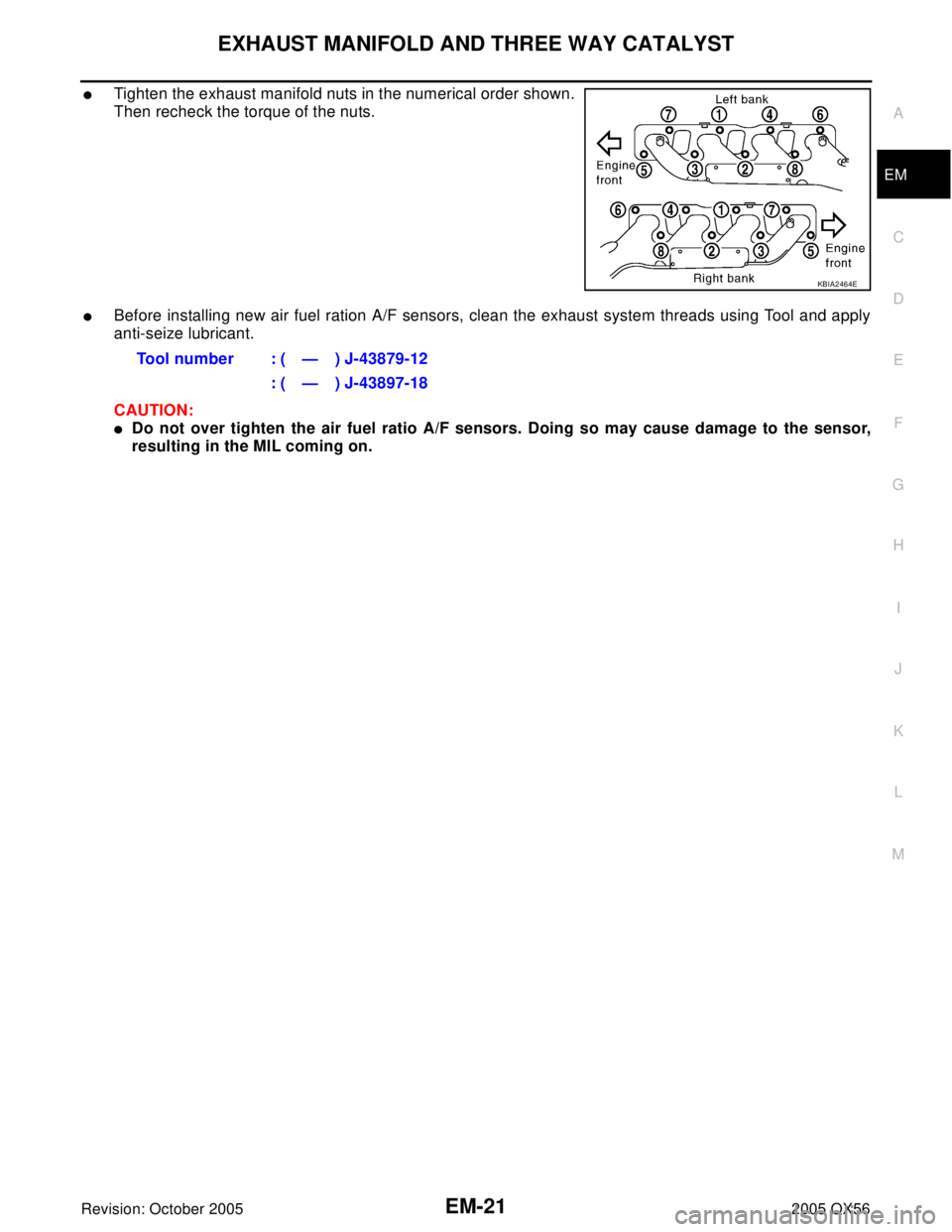
�Tighten the exhaust manifold nuts in the numerical order shown.
Then recheck the torque of the nuts.
�Before installing new air fuel ration A/F sensors, clean the exhaust system threads using Tool and apply
anti-seize lubricant.
CAUTION:
�Do not over tighten the air fuel ratio A/F sensors. Doing so may cause damage to the sensor,
resulting in the MIL coming on.
KBIA2464E
Tool number : ( — ) J-43879-12
: ( — ) J-43897-18
Page 1944 of 3419

TIMING CHAIN
EM-41
C
D
E
F
G
H
I
J
K
L
MA
EM
Revision: October 20052005 QX56
9. Install the chain tensioner cover.
�Apply liquid gasket as shown.
Use Genuine RTV Silicone Sealant or equivalent. Refer to
GI-45, "
Recommended Chemical Products and Sealants"
.
10. Install the front cover as follows:
a. Install a new O-ring on the cylinder block.
b. Apply liquid gasket as shown.
Use Genuine RTV Silicone Sealant or equivalent. Refer to
GI-45, "
Recommended Chemical Products and Sealants".
c. Check again that the timing mating marks on the timing chain
and on each sprocket are aligned. Then install the front cover.
d. Install the bolts in the numerical order shown.
e. After tightening, re-tighten to the specified torque.
CAUTION:
Be sure to wipe off any excessive liquid gasket leaking onto
surface mating with oil pan.
11. Install the chain case cover (right bank) and (left bank) as fol-
lows:
a. Apply liquid gasket as shown.
Use Genuine RTV Silicone Sealant or equivalent. Refer to
GI-45, "
Recommended Chemical Products and Sealants".
CAUTION:
The start and end of the application of the liquid gasket
should be crossed at a position that cannot be seen after
attaching the chain case cover.
KBIA2547E
KBIA2516E
KBIA2517E
M6 × 50 mm (1.97 in) : No. 1, 20, 25, 26, 27
M6 × 80 mm (3.15 in) : No. 4, 5, 7
M6 × 20 mm (0.79 in) : Except the above
KBIA2478E
KBIA2481E
Page 1945 of 3419

EM-42Revision: October 2005
TIMING CHAIN
2005 QX56
b. Install the bolts in the numerical order shown.
12. Install the crankshaft pulley.
�Install the key of the crankshaft.
�Insert the pulley by lightly tapping it.
CAUTION:
Do not tap pulley on the side surface where the belt is installed (outer circumference).
13. Tighten the crankshaft pulley bolt.
�Lock the crankshaft using suitable tool, then tighten the bolt.
�Perform the following steps for angular tightening:
a. Apply engine oil onto the threaded parts of the bolt and seating area.
b. Select the one most visible notch of the four on the bolt flange.
Corresponding to the selected notch, put a mating mark (such
as paint) on the crankshaft pulley.
14. Rotate the crankshaft pulley in normal direction (clockwise when
viewed from engine front) to check for parts interference.
15. Installation of the remaining components is in the reverse order
of removal.
WBIA0468E
Crankshaft pulley bolt torque
Step 1 : 93.1 N·m (9.5 kg-m, 69 ft-lb)
Step 2 : additional 90° (angle tightening)
KBIA2519E
Page 1949 of 3419

EM-46Revision: October 2005
CAMSHAFT
2005 QX56
INSPECTION AFTER REMOVAL
Camshaft Runout
1. Put V block on precise flat work bench, and support No. 1 and
No. 5 journals of the camshaft.
2. Set dial indicator vertically to No. 3 journal.
3. Turn the camshaft to one direction, and measure the camshaft
runout on the dial indicator (total indicator reading).
�If measurement exceeds specification, replace the camshaft.
Camshaft Cam Height
�Measure the camshaft cam height.
�If measurement is not within the specifications, replace the cam-
shaft.
Camshaft Journal Clearance
Camshaft Journal Diameter
�Measure the diameter of the camshaft journal.
Camshaft Bracket Inner Diameter
�Tighten the camshaft bracket bolt to the specified torque.
�Measure the inner diameter of the camshaft bracket.
Calculation of Camshaft Journal Clearance
(Journal clearance) = (camshaft bracket inner diameter) – (camshaft
journal diameter)
�If measurement is not within specification, replace either or both
camshaft and cylinder head.
NOTE:
The inner diameter of the camshaft bracket is manufactured together with the cylinder head. Replace the
whole cylinder head as an assembly.Standard : Less than 0.02 mm (0.0008 in)
EMK0641D
Standard cam height
(intake & exhaust): 44.465 - 44.655 mm
(1.7506 - 1.7581 in)
Cam wear limit
(intake & exhaust): 0.02 mm (0.0008 in)
PBIC0039E
Standard diameter : 25.953 - 25.970 mm
(1.0218 - 1.0224 in)
PBIC0040E
Standard : 26.000 - 26.021 mm (1.0236 - 1.0244 in)
Standard : 0.030 - 0.068 mm (0.0012 - 0.0027 in)
PBIC1645E
Page 1953 of 3419
EM-50Revision: October 2005
CAMSHAFT
2005 QX56
–Position No. 1 camshaft bracket close to the mounting posi-
tion, and then install it to prevent from touching liquid gasket
applied to each surface.
–Temporarily tighten the front cover bolts (4 for each bank) as
shown.
4. Tighten the camshaft bracket bolts as follows:
CAUTION:
After tightening the camshaft bracket bolts, be sure to wipe
off excessive liquid gasket from the parts listed below.
�Mating surface of rocker cover
�Mating surface of front cover
a. Tighten the front cover bolts (4 for each bank) as shown to the
specified torque.
SBIA0259E
KBIA2486E
Camshaft bracket bolts
Step 1 (bolts 9 - 12) : 1.96 N·m (0.2 kg-m, 17 in-lb)
Step 2 (bolts 1 - 8) : 1.96 N·m (0.2 kg-m, 17 in-lb)
Step 3 (all bolts) : 5.88 N·m (0.6 kg-m, 52 in-lb)
Step 4 (all bolts) : 10.4 N·m (1.1 kg-m, 92 in-lb)
KBIA2522E
Front cover bolts : 11.0 N·m (1.1 kg-m, 8ft - lb)
KBIA2486E
Page 1973 of 3419

EM-70Revision: October 2005
ENGINE ASSEMBLY
2005 QX56
5. Remove the cowl extension. Refer to EI-18, "Removal and Installation" .
6. Remove the engine room cover using power tools.
7. Remove the air duct and air cleaner case assembly EM-14, "
REMOVAL" .
8. Disconnect the vacuum hose between the vehicle and engine and set it aside.
9. Remove the radiator assembly and hoses. Refer to CO-12, "
REMOVAL" .
10. Remove the drive belts. Refer to EM-12, "
Removal" .
11. Remove the fan blade. Refer to CO-15, "
REMOVAL" .
12. Disconnect the engine room harness from the fuse box and set it aside.
13. Disconnect the ECM.
14. Disconnect the engine room harness from the engine side and set it aside.
15. Disconnect the engine harness grounds.
16. Disconnect the power steering reservoir tank from the engine and move it aside.
17. Disconnect the power steering oil pump from the engine. Move it aside and secure it using suitable wire or
rope. Refer to PS-26, "
REMOVAL" .
18. Remove the A/C compressor bolts and set the compressor aside. Refer to ATC-179, "
REMOVAL" .
19. Disconnect the brake booster vacuum line.
20. Disconnect the EVAP line.
21. Disconnect the fuel hose at the engine side connection. Refer to EM-29, "
REMOVAL" .
22. Disconnect the heater hoses at cowl, and install plugs to avoid leakage of engine coolant.
23. Remove the A/T oil level indicator and indicator tube upper bolts.
24. Remove the front final drive assembly (4x4 only). Refer to FFD-11, "
REMOVAL" .
25. Remove the exhaust manifolds. Refer to EM-19, "
Removal and Installation" .
26. Install the engine slingers into the left bank cylinder head and
right bank cylinder head.
27. Remove the A/T. Refer to AT-244, "
Removal and Installation
(4x2)" or AT-247, "Removal and Installation (4x4)" .
28. Lift using hoist and secure the engine in position.
29. Remove the engine assembly from the vehicle, avoid interfer-
ence with the vehicle body.
CAUTION:
�Before and during lifting, always check if any harnesses
are left connected.
30. Remove the parts that may restrict installation of the engine to the engine stand.
NOTE:
This procedure is described assuming that you use an engine stand mounting to the surface to which the
transmission mounts.
a. Remove the drive plate.
�Holding the crankshaft pulley bolt, lock the crankshaft to remove the drive plate bolts.
�Loosen the bolts diagonally.
WBIA0464E
Engine slinger torque: 45.0 N·m (4.6 kg-m, 33 ft-lb)
PBIC1556E
Page 1980 of 3419

CYLINDER BLOCK
EM-77
C
D
E
F
G
H
I
J
K
L
MA
EM
Revision: October 20052005 QX56
ASSEMBLY
1. Fully air-blow the coolant and oil passages in the cylinder block, cylinder bore, and crankcase to remove
any foreign material.
CAUTION:
Use goggles to protect your eyes.
2. Install each plug to the cylinder block (only screw-type plugs are
shown).
�Apply liquid gasket.
Use Genuine Thread Sealant or equivalent. Refer to GI-
45, "Recommended Chemical Products and Sealants".
�Replace copper washers with new ones.
�Tighten each plug as specified below.
3. Install main bearings and thrust bearings.
a. Remove any dust, dirt, and oil on the bearing mating surfaces of
the cylinder block and the main bearing caps.
b. Install thrust bearings to both sides of the No. 3 journal housing
on the cylinder block and main bearing caps.
�Install thrust bearings with the oil groove facing the crankshaft
arm (outside).
�Install thrust bearings with a protrusion in the center on the
main bearing caps.
c. Install main bearings paying attention to the direction.
�Install the one with oil holes onto the cylinder block and the
one without oil holes onto the main bearing cap.
�Before installing bearings, apply engine oil to bearing surface
(inside). Do not apply oil to the back surface, but thoroughly
clean it.
�When installing, align the bearing stopper to the notch.
�Ensure the oil holes on the cylinder block and those on the
corresponding bearing are aligned.
4. Install pilot converter to the crankshaft using suitable tool.
5. Install crankshaft to the cylinder block.
�While turning crankshaft by hand, make sure it turns
smoothly.
Part Washer Tightening torque
A Yes 53.9 N·m (5.5 kg-m, 40 ft-lb)
B No 19.6 N·m (2.0 kg-m, 15 ft-lb)
C Yes 62.7 N·m (6.4 kg-m, 46 ft-lb)
D Yes 62.7 N·m (6.4 kg-m, 46 ft-lb)
WBIA0419E
PBIC0093E
PBIC0094E
EMP0569D
Page 1994 of 3419

CYLINDER BLOCK
EM-91
C
D
E
F
G
H
I
J
K
L
MA
EM
Revision: October 20052005 QX56
�If out of specification, replace piston ring. If the gap still exceeds the limit even with a new ring, re-bore the
cylinder and use oversized piston and piston ring.
CONNECTING ROD BEND AND TORSION
�Check connecting rod alignment using suitable tool.
�If measurement exceeds the limit, replace connecting rod
assembly.
CONNECTING ROD BEARING (BIG END)
�Install the connecting rod cap without the connecting rod bearing
installed. After tightening the connecting rod bolt to the specified
torque, measure the connecting rod large end inside diameter.
Refer to EM-77, "
ASSEMBLY" .
�If measurement exceeds the standard, replace connecting rod.
CONNECTING ROD BUSHING OIL CLEARANCE (SMALL END)
Connecting Rod Inside Diameter (Small End)
�Measure inside diameter of bushing using suitable tool.Limit:
Bend
: 0.15 mm (0.0059 in) per 100 mm (3.94 in) length
To r s i o n
: 0.30 mm (0.0118 in) per 100 mm (3.94 in) length
SEM 00 3F
SEM 03 8F
Standard : 57.000 - 57.013 mm (2.2441 - 2.2446 in)
PBIC1641E
Standard : 22.000 - 22.006 mm (0.8661 - 0.8664 in)
PBIC0120E