Page 1030 of 4731
IVIS (INFINITI VEHICLE IMMOBILIZER SYSTEM-NATS) BL-215
C
D E
F
G H
J
K L
M A
B
BL
Revision: 2005 July 2005 FX
System CompositionAIS004PC
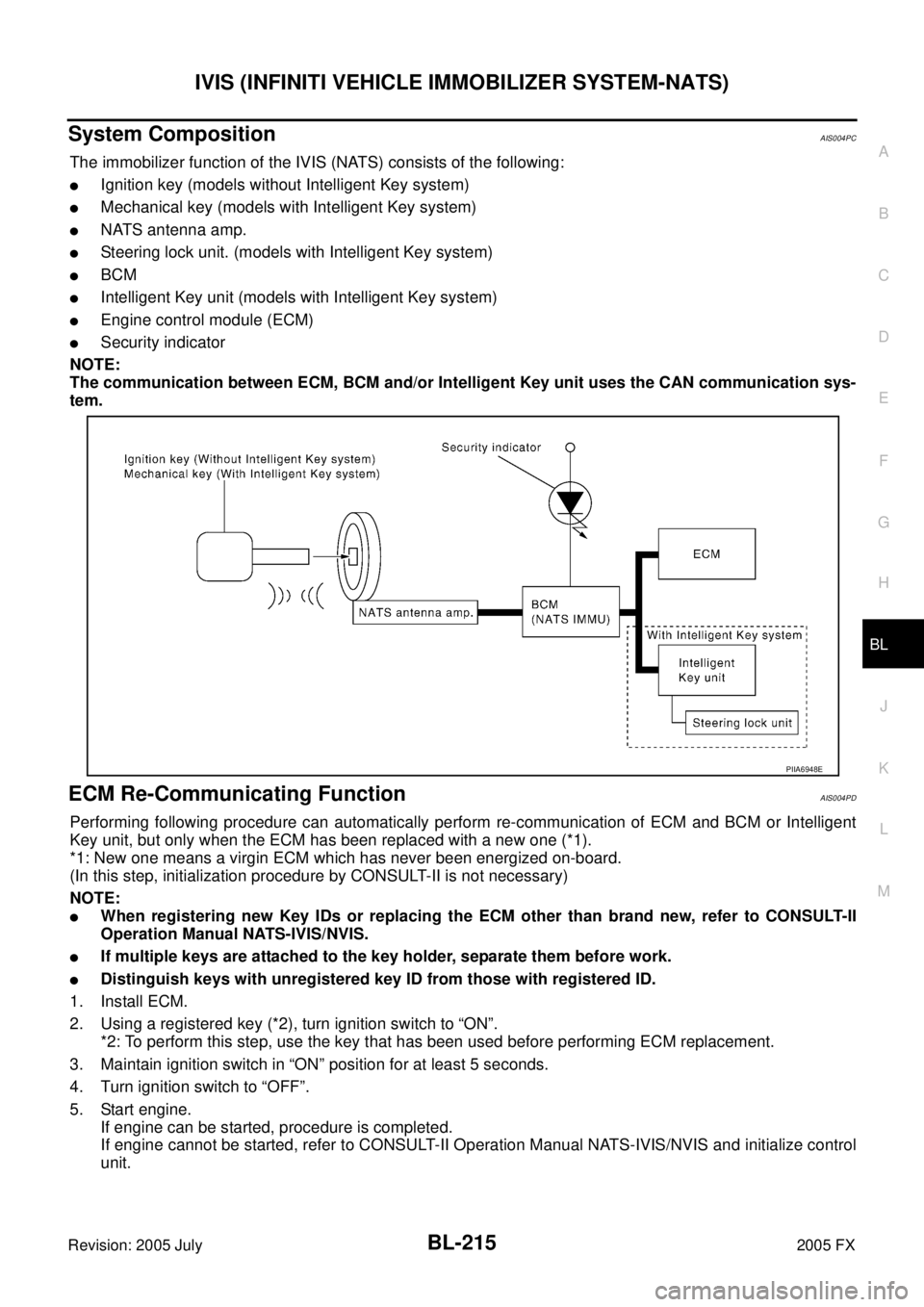
The immobilizer function of the IVIS (NATS) consists of the following:
�Ignition key (models without Intelligent Key system)
�Mechanical key (models with Intelligent Key system)
�NATS antenna amp.
�Steering lock unit. (models with Intelligent Key system)
�BCM
�Intelligent Key unit (models with Intelligent Key system)
�Engine control module (ECM)
�Security indicator
NOTE:
The communication between ECM, BCM and/or Intelligent Key unit uses the CAN communication sys-
tem.
ECM Re-Communicating FunctionAIS004PD
Performing following procedure can automatically perform re-communication of ECM and BCM or Intelligent
Key unit, but only when the ECM has been replaced with a new one (*1).
*1: New one means a virgin ECM which has never been energized on-board.
(In this step, initialization procedure by CONSULT-II is not necessary)
NOTE:
�When registering new Key IDs or replacing the ECM other than brand new, refer to CONSULT-II
Operation Manual NATS-IVIS/NVIS.
�If multiple keys are attached to the key holder, separate them before work.
�Distinguish keys with unregistered key ID from those with registered ID.
1. Install ECM.
2. Using a registered key (*2), turn ignition switch to “ON”. *2: To perform this step, use the key that has been used before performing ECM replacement.
3. Maintain ignition switch in “ON” position for at least 5 seconds.
4. Turn ignition switch to “OFF”.
5. Start engine. If engine can be started, procedure is completed.
If engine cannot be started, refer to CONSULT-II Operation Manual NATS-IVIS/NVIS and initialize control
unit.
PIIA6948E
Page 1034 of 4731
IVIS (INFINITI VEHICLE IMMOBILIZER SYSTEM-NATS) BL-219
C
D E
F
G H
J
K L
M A
B
BL
Revision: 2005 July 2005 FX
Terminals and Reference Value for Steering Lock Unit/with Intelligent Key Sys-
tem
AIS004PF
Terminals and Reference Value for Intelligent Key Unit/with Intelligent Key Sys-
tem
AIS004PG
Te r -
minal
No. Wire
color Signal Designation Measuring condition
Voltage (V)
(Approx.)
Ignition knob
position Operation or conditions
1 L/R Power source (Fuse) LOCK — Battery voltage
2R/W Steering lock unit
power supply LOCK — 5
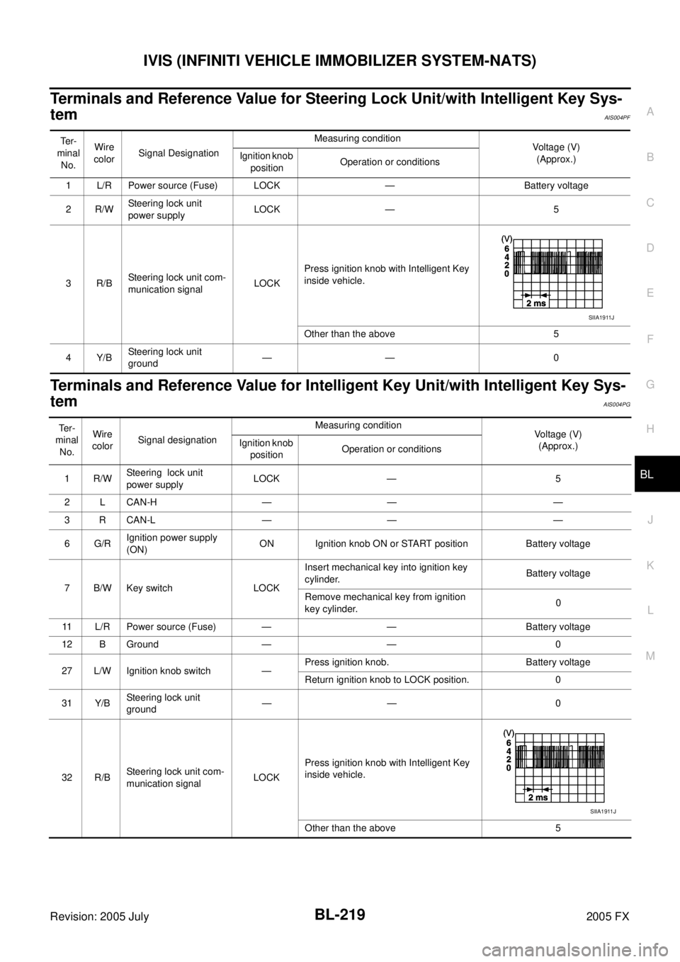
3R/B Steering lock unit com-
munication signal LOCK Press ignition knob with Intelligent Key
inside vehicle.
Other than the above 5
4Y/B Steering lock unit
ground —— 0
SIIA1911J
Te r -
minal
No. Wire
color Signal designation Measuring condition
Voltage (V)
(Approx.)
Ignition knob
position Operation or conditions
1R/W Steering lock unit
power supply LOCK — 5
2 L CAN-H — — —
3 R CAN-L — — —
6G/R Ignition power supply
(ON) ON Ignition knob ON or START position Battery voltage
7 B/W Key switch LOCK Insert mechanical key into ignition key
cylinder. Battery voltage
Remove mechanical key from ignition
key cylinder. 0
11 L/R Power source (Fuse) — — Battery voltage
12 B Ground — — 0
27 L/W Ignition knob switch — Press ignition knob. Battery voltage
Return ignition knob to LOCK position. 0
31 Y/B Steering lock unit
ground —— 0
32 R/B Steering lock unit com-
munication signal LOCK Press ignition knob with Intelligent Key
inside vehicle.
Other than the above 5
SIIA1911J
Page 1035 of 4731

BL-220
IVIS (INFINITI VEHICLE IMMOBILIZER SYSTEM-NATS)
Revision: 2005 July 2005 FX
Terminals and Reference Value for BCMAIS004PH
*: With Intelligent Key system Te r -
minal No. Wire
color Signal designation Measuring condition
Voltage (V)
(Approx.)
Ignition knob
position Operation or conditions
21 G/B NATS antenna apm. — Ignition knob OFF → ON position Tester pointer should move just
after turning ignition knob “ON”
23 G/OR Security indicator lamp LOCK Goes OFF
→ illuminates (Every 2.4
seconds) Battery voltage
→ 0
25 BR NATS antenna amp. — Ignition knob or switch OFF
→ ON posi-
tion Tester pointer should move just
after turning ignition knob “ON”
37* B/W Key switch — Insert mechanical key into ignition key
cylinder Battery voltage
Remove mechanical key from ignition
key cylinder 0
38 W/L Ignition power supply
(ON) ON Ignition knob ON or START position Battery voltage
39 L CAN-H — — —
40 R CAN-L — — —
42 L/R Power source (Fuse) — — Battery voltage
49 B Ground — — 0
52 B Ground — — 0
55 G Power source (Fuse) — — Battery voltage
Page 1036 of 4731
IVIS (INFINITI VEHICLE IMMOBILIZER SYSTEM-NATS) BL-221
C
D E
F
G H
J
K L
M A
B
BL
Revision: 2005 July 2005 FX
CONSULT-IIAIS004PI
CONSULT-II INSPECTION PROCEDURE
CAUTION:
If CONSULT-II is used with no connection CONSULT-II CONVERTER, malfunctions might be detected
in self-diagnosis depending on control unit which carry out CAN Communication.
1. Turn ignition switch OFF.
2. Insert IVIS (NATS) program card into CONSULT-II.
3. Connect CONSULT-II and “CONSULT-II CONVERTER” to data link connector.
4. Turn ignition switch ON.
5. Touch “START”.
6. Touch “OTHER”.
7. Perform each diagnostic test mode according to each service procedure.
For further information, see the CONSULT-II Operation Manual,
NATS-IVIS/NVIS. Program card : NATS (AEN02C)
PBIB0196E
PBR455D
PIIA6816E
SEL150X
Page 1042 of 4731
IVIS (INFINITI VEHICLE IMMOBILIZER SYSTEM-NATS) BL-227
C
D E
F
G H
J
K L
M A
B
BL
Revision: 2005 July 2005 FX
Diagnostic Procedure 2AIS004PN
Self-diagnostic results:
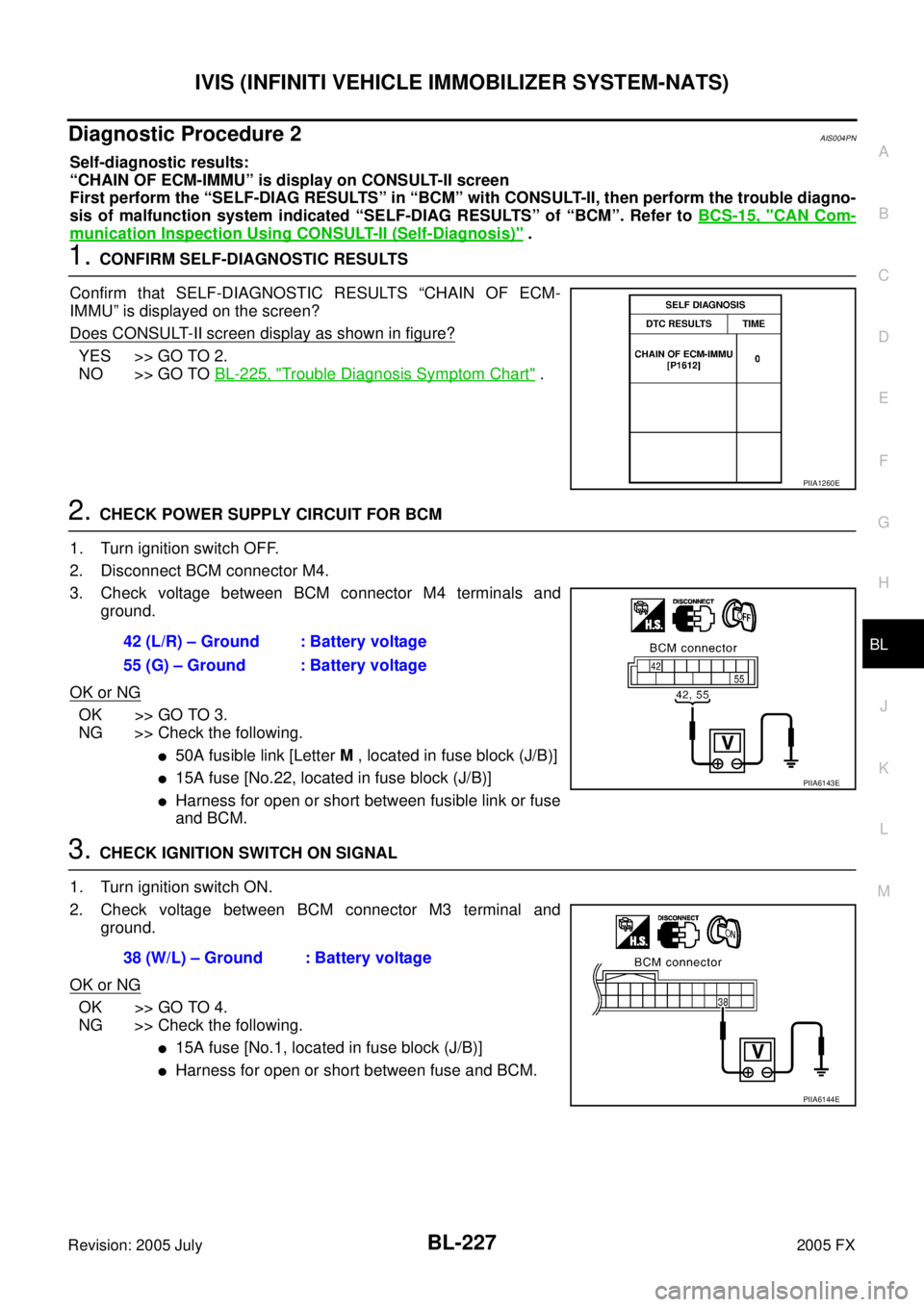
“CHAIN OF ECM-IMMU” is display on CONSULT-II screen
First perform the “SELF-DIAG RESULTS” in “BCM” with CONSULT-II, then perform the trouble diagno-
sis of malfunction system indicated “SELF-DIAG RESULTS” of “BCM”. Refer to BCS-15, "
CAN Com-
munication Inspection Using CONSULT-II (Self-Diagnosis)" .
1. CONFIRM SELF-DIAGNOSTIC RESULTS
Confirm that SELF-DIAGNOSTIC RESULTS “CHAIN OF ECM-
IMMU” is displayed on the screen?
Does CONSULT-II screen display as shown in figure?
YES >> GO TO 2.
NO >> GO TO BL-225, "
Trouble Diagnosis Symptom Chart" .
2. CHECK POWER SUPPLY CIRCUIT FOR BCM
1. Turn ignition switch OFF.
2. Disconnect BCM connector M4.
3. Check voltage between BCM connector M4 terminals and ground.
OK or NG
OK >> GO TO 3.
NG >> Check the following.
�50A fusible link [Letter M , located in fuse block (J/B)]
�15A fuse [No.22, located in fuse block (J/B)]
�Harness for open or short between fusible link or fuse
and BCM.
3. CHECK IGNITION SWITCH ON SIGNAL
1. Turn ignition switch ON.
2. Check voltage between BCM connector M3 terminal and ground.
OK or NG
OK >> GO TO 4.
NG >> Check the following.
�15A fuse [No.1, located in fuse block (J/B)]
�Harness for open or short between fuse and BCM.
PIIA1260E
42 (L/R) – Ground : Battery voltage
55 (G) – Ground : Battery voltage
PIIA6143E
38 (W/L) – Ground : Battery voltage
PIIA6144E
Page 1043 of 4731
BL-228
IVIS (INFINITI VEHICLE IMMOBILIZER SYSTEM-NATS)
Revision: 2005 July 2005 FX
4. CHECK GROUND CIRCUIT FOR BCM
1. Turn ignition switch OFF.
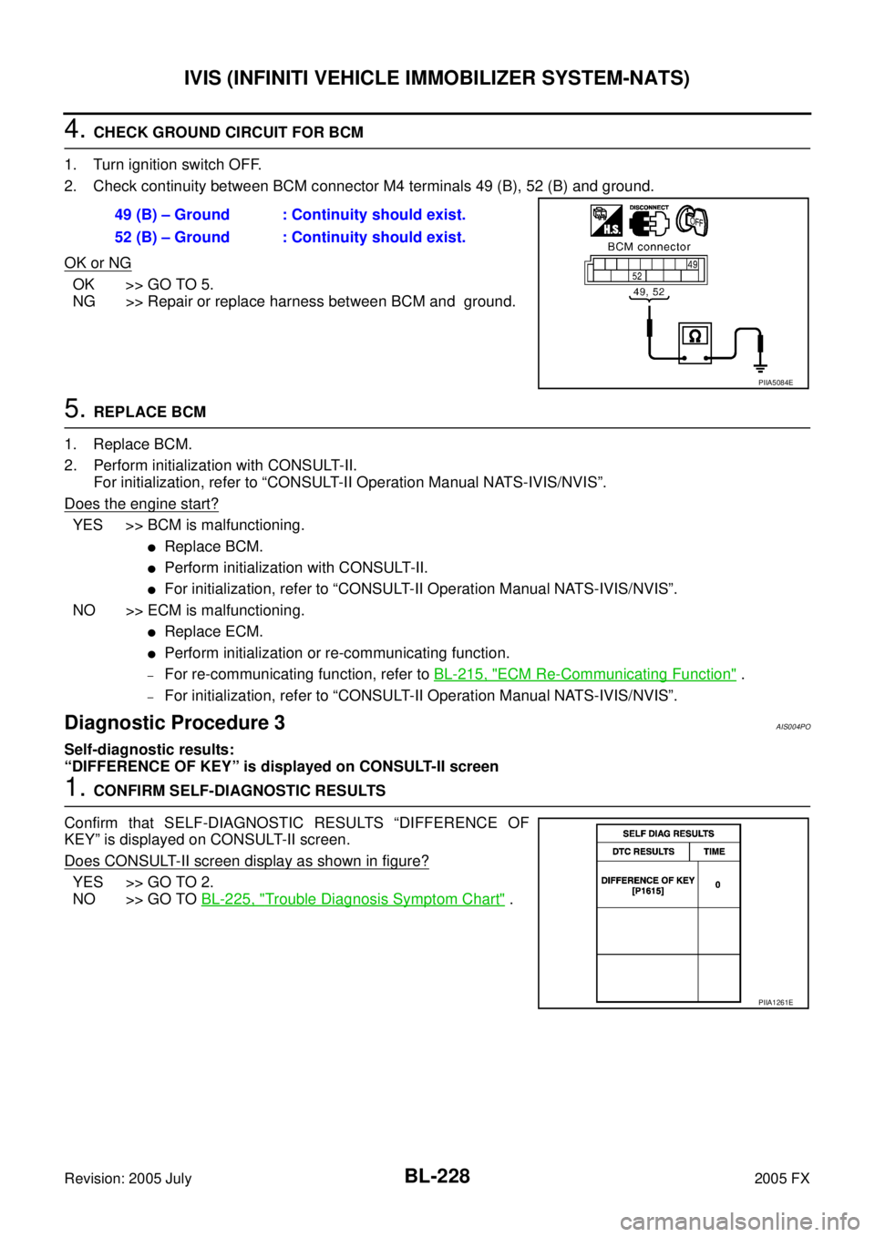
2. Check continuity between BCM connector M4 terminals 49 (B), 52 (B) and ground.
OK or NG
OK >> GO TO 5.
NG >> Repair or replace harness between BCM and ground.
5. REPLACE BCM
1. Replace BCM.
2. Perform initialization with CONSULT-II. For initialization, refer to “CONSULT-II Operation Manual NATS-IVIS/NVIS”.
Does the engine start?
YES >> BCM is malfunctioning.
�Replace BCM.
�Perform initialization with CONSULT-II.
�For initialization, refer to “CONSULT-II Operation Manual NATS-IVIS/NVIS”.
NO >> ECM is malfunctioning.
�Replace ECM.
�Perform initialization or re-communicating function.
–For re-communicating function, refer to BL-215, "ECM Re-Communicating Function" .
–For initialization, refer to “CONSULT-II Operation Manual NATS-IVIS/NVIS”.
Diagnostic Procedure 3AIS004PO
Self-diagnostic results:
“DIFFERENCE OF KEY” is displayed on CONSULT-II screen
1. CONFIRM SELF-DIAGNOSTIC RESULTS
Confirm that SELF-DIAGNOSTIC RESULTS “DIFFERENCE OF
KEY” is displayed on CONSULT-II screen.
Does CONSULT-II screen display as shown in figure?
YES >> GO TO 2.
NO >> GO TO BL-225, "
Trouble Diagnosis Symptom Chart" .
49 (B) – Ground : Continuity should exist.
52 (B) – Ground : Continuity should exist.
PIIA5084E
PIIA1261E
Page 1045 of 4731
BL-230
IVIS (INFINITI VEHICLE IMMOBILIZER SYSTEM-NATS)
Revision: 2005 July 2005 FX
Diagnostic Procedure 5AIS004PQ
Self-diagnostic results:
“LOCK MODE” displayed on CONSULT-II screen
1. CONFIRM SELF-DIAGNOSTIC RESULTS
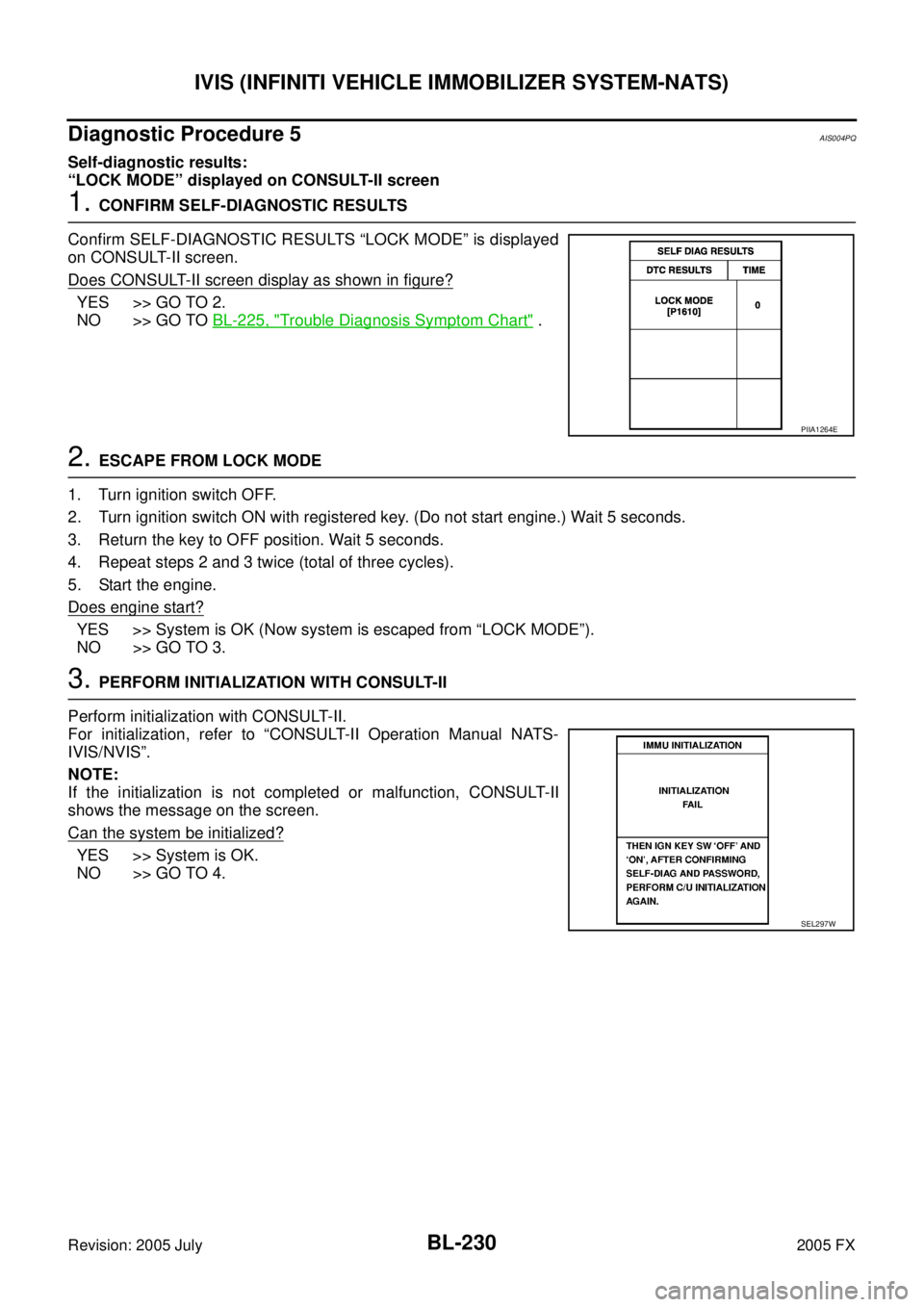
Confirm SELF-DIAGNOSTIC RESULTS “LOCK MODE” is displayed
on CONSULT-II screen.
Does CONSULT-II screen display as shown in figure?
YES >> GO TO 2.
NO >> GO TO BL-225, "
Trouble Diagnosis Symptom Chart" .
2. ESCAPE FROM LOCK MODE
1. Turn ignition switch OFF.
2. Turn ignition switch ON with registered key. (Do not start engine.) Wait 5 seconds.
3. Return the key to OFF position. Wait 5 seconds.
4. Repeat steps 2 and 3 twice (total of three cycles).
5. Start the engine.
Does engine start?
YES >> System is OK (Now system is escaped from “LOCK MODE”).
NO >> GO TO 3.
3. PERFORM INITIALIZATION WITH CONSULT-II
Perform initialization with CONSULT-II.
For initialization, refer to “CONSULT-II Operation Manual NATS-
IVIS/NVIS”.
NOTE:
If the initialization is not completed or malfunction, CONSULT-II
shows the message on the screen.
Can the system be initialized?
YES >> System is OK.
NO >> GO TO 4.
PIIA1264E
SEL297W
Page 1048 of 4731
IVIS (INFINITI VEHICLE IMMOBILIZER SYSTEM-NATS) BL-233
C
D E
F
G H
J
K L
M A
B
BL
Revision: 2005 July 2005 FX
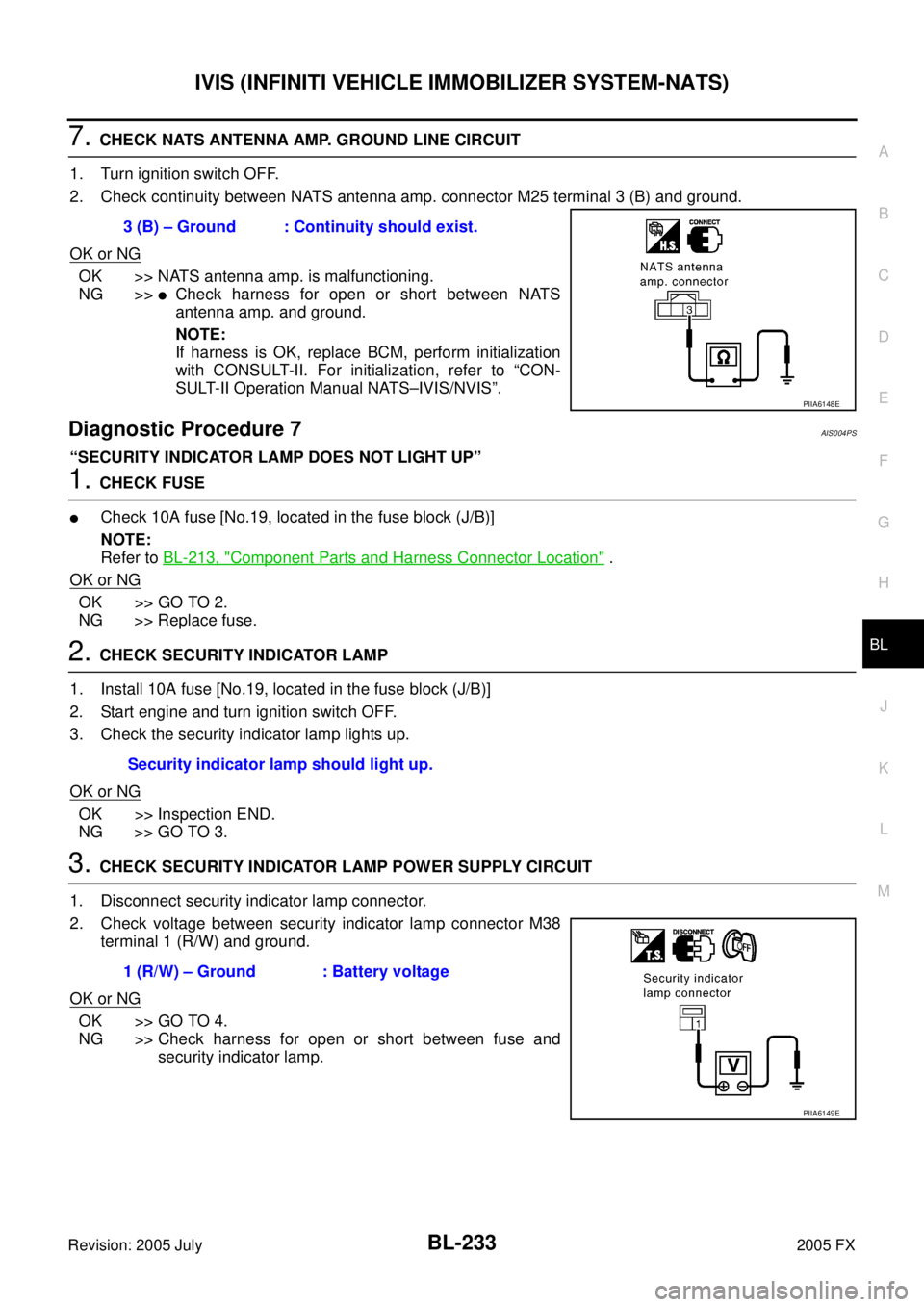
7. CHECK NATS ANTENNA AMP. GROUND LINE CIRCUIT
1. Turn ignition switch OFF.
2. Check continuity between NATS antenna amp. connector M25 terminal 3 (B) and ground.
OK or NG
OK >> NATS antenna amp. is malfunctioning.
NG >>
�Check harness for open or short between NATS
antenna amp. and ground.
NOTE:
If harness is OK, replace BCM, perform initialization
with CONSULT-II. For initialization, refer to “CON-
SULT-II Operation Manual NATS–IVIS/NVIS”.
Diagnostic Procedure 7AIS004PS
“SECURITY INDICATOR LAMP DOES NOT LIGHT UP”
1. CHECK FUSE
�Check 10A fuse [No.19, located in the fuse block (J/B)]
NOTE:
Refer to BL-213, "
Component Parts and Harness Connector Location" .
OK or NG
OK >> GO TO 2.
NG >> Replace fuse.
2. CHECK SECURITY INDICATOR LAMP
1. Install 10A fuse [No.19, located in the fuse block (J/B)]
2. Start engine and turn ignition switch OFF.
3. Check the security indicator lamp lights up.
OK or NG
OK >> Inspection END.
NG >> GO TO 3.
3. CHECK SECURITY INDICATOR LAMP POWER SUPPLY CIRCUIT
1. Disconnect security indicator lamp connector.
2. Check voltage between security indicator lamp connector M38 terminal 1 (R/W) and ground.
OK or NG
OK >> GO TO 4.
NG >> Check harness for open or short between fuse and security indicator lamp.
3 (B) – Ground : Continuity should exist.
PIIA6148E
Security indicator lamp should light up.
1 (R/W) – Ground : Battery voltage
PIIA6149E