Page 4373 of 4731
RFD-4
PREPARATION
Revision: 2005 July 2005 FX
KV38107900
(J-39352)
Protector Installing side flange
KV38100800
(J-25604-01)
Attachment
a: 541 mm (21.30 in)
b: 200 mm (7.87 in) Fixing unit assembly
ST3127S000
(J-25765-A)
Preload gauge
1: GG91030000 (J-25765)
Torque wrench
2: HT62940000 (—)
Socket adapter (1/2 ″)
3: HT62900000 (—)
Socket adapter (3/8 ″) Measuring pinion bearing preload and total
preload
K V 1 0 1111 0 0
(J-37228)
Seal cutter Removing rear cover
ST3306S001
(J-22888-D)
Differential side bearing puller set
1: ST33051001 (J-22888-20)
Puller
2: ST33061000 (J-8107-2)
Base
a: 28.5 mm (1.122 in) dia.
b: 38 mm (1.50 in) dia. Removing and installing side bearing inner
race
ST30031000
(J-22912-01)
Replacer Removing pinion rear bearing inner race
Tool number
(Kent-Moore No.)
Tool name Description
S-NT129
SDIA0267E
NT124
S-NT046
NT072
ZZA0700D
Page 4374 of 4731
PREPARATION RFD-5
C E F
G H
I
J
K L
M A
B
RFD
Revision: 2005 July 2005 FX
KV40105230
(—)
Drift
a: 92 mm (3.62 in) dia.
b: 86 mm (3.39 in) dia.
c: 45 mm (1.77 in) dia. Installing pinion rear bearing outer race
ST30613000
(J-25742-3)
Drift
a: 72 mm (2.83 in) dia.
b: 48 mm (1.89 in) dia. Installing pinion front bearing outer race
ST30611000
(J-25742-1)
Drift bar Installing pinion front bearing outer race (Use
with ST30613000)
ST30901000
(J-26010-01)
Drift
a: 79 mm (3.11 in) dia.
b: 45 mm (1.77 in) dia.
c: 35.2 mm (1.386 in) dia. Installing pinion rear bearing inner race
KV38100300
(J-25523)
Drift
a: 54 mm (2.13 in) dia.
b: 46 mm (1.81 in) dia.
c: 32 mm (1.26 in) dia. Installing side bearing inner race
(J-8129)
Spring gauge Measuring turning torque
Tool number
(Kent-Moore No.)
Tool name Description
PDIA0591E
ZZA1000D
S-NT090
ZZA0978D
ZZA1046D
NT127
Page 4378 of 4731
DIFFERENTIAL GEAR OIL RFD-9
C E F
G H
I
J
K L
M A
B
RFD
Revision: 2005 July 2005 FX
DIFFERENTIAL GEAR OILPFP:KLD30
Changing Differential Gear OilADS001AK
DRAINING
1. Stop engine.
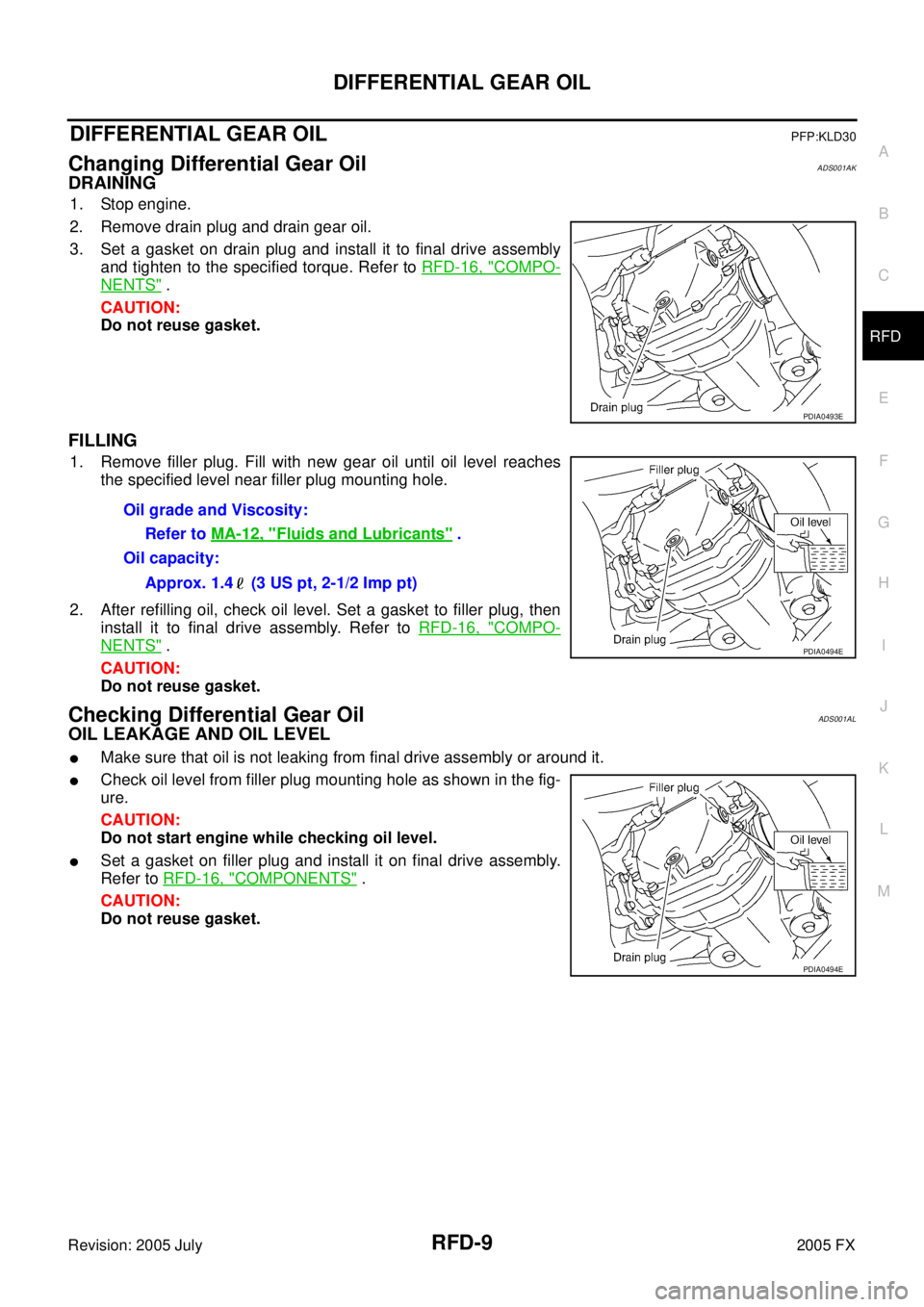
2. Remove drain plug and drain gear oil.
3. Set a gasket on drain plug and install it to final drive assembly and tighten to the specified torque. Refer to RFD-16, "
COMPO-
NENTS" .
CAUTION:
Do not reuse gasket.
FILLING
1. Remove filler plug. Fill with new gear oil until oil level reaches
the specified level near filler plug mounting hole.
2. After refilling oil, check oil level. Set a gasket to filler plug, then install it to final drive assembly. Refer to RFD-16, "
COMPO-
NENTS" .
CAUTION:
Do not reuse gasket.
Checking Differential Gear OilADS001AL
OIL LEAKAGE AND OIL LEVEL
�Make sure that oil is not leaking from final drive assembly or around it.
�Check oil level from filler plug mounting hole as shown in the fig-
ure.
CAUTION:
Do not start engine while checking oil level.
�Set a gasket on filler plug and install it on final drive assembly.
Refer to RFD-16, "
COMPONENTS" .
CAUTION:
Do not reuse gasket.
PDIA0493E
Oil grade and Viscosity:
Refer to MA-12, "
Fluids and Lubricants" .
Oil capacity:
Approx. 1.4 (3 US pt, 2-1/2 Imp pt)
PDIA0494E
PDIA0494E
Page 4380 of 4731
FRONT OIL SEAL RFD-11
C E F
G H
I
J
K L
M A
B
RFD
Revision: 2005 July 2005 FX
INSTALLATION
1. Apply multi-purpose grease to front oil seal lips.
2. Using the drift, install front oil seal as shown in figure.
CAUTION:
�Do not reuse oil seal.
�When installing, do not incline oil seal.
3. Align the matching mark of drive pinion with the matching mark A of companion flange, then install the companion flange.
4. Apply gear oil on the screw part of drive pinion and the seating surface of drive pinion lock nut.
5. Install drive pinion lock nut with the flange wrench, tighten to the specified torque. Refer to RFD-16, "
COMPONENTS" .
CAUTION:
Do not reuse drive pinion lock nut.
6. Install propeller shaft. Refer to PR-9, "
Removal and Installation"
. Tool number : ST30720000 (J-25405)
PDIA0565E
PDIA0478E
Tool number : KV40104000 ( — )
SDIA1589E
Page 4384 of 4731
REAR FINAL DRIVE ASSEMBLY RFD-15
C E F
G H
I
J
K L
M A
B
RFD
Revision: 2005 July 2005 FX
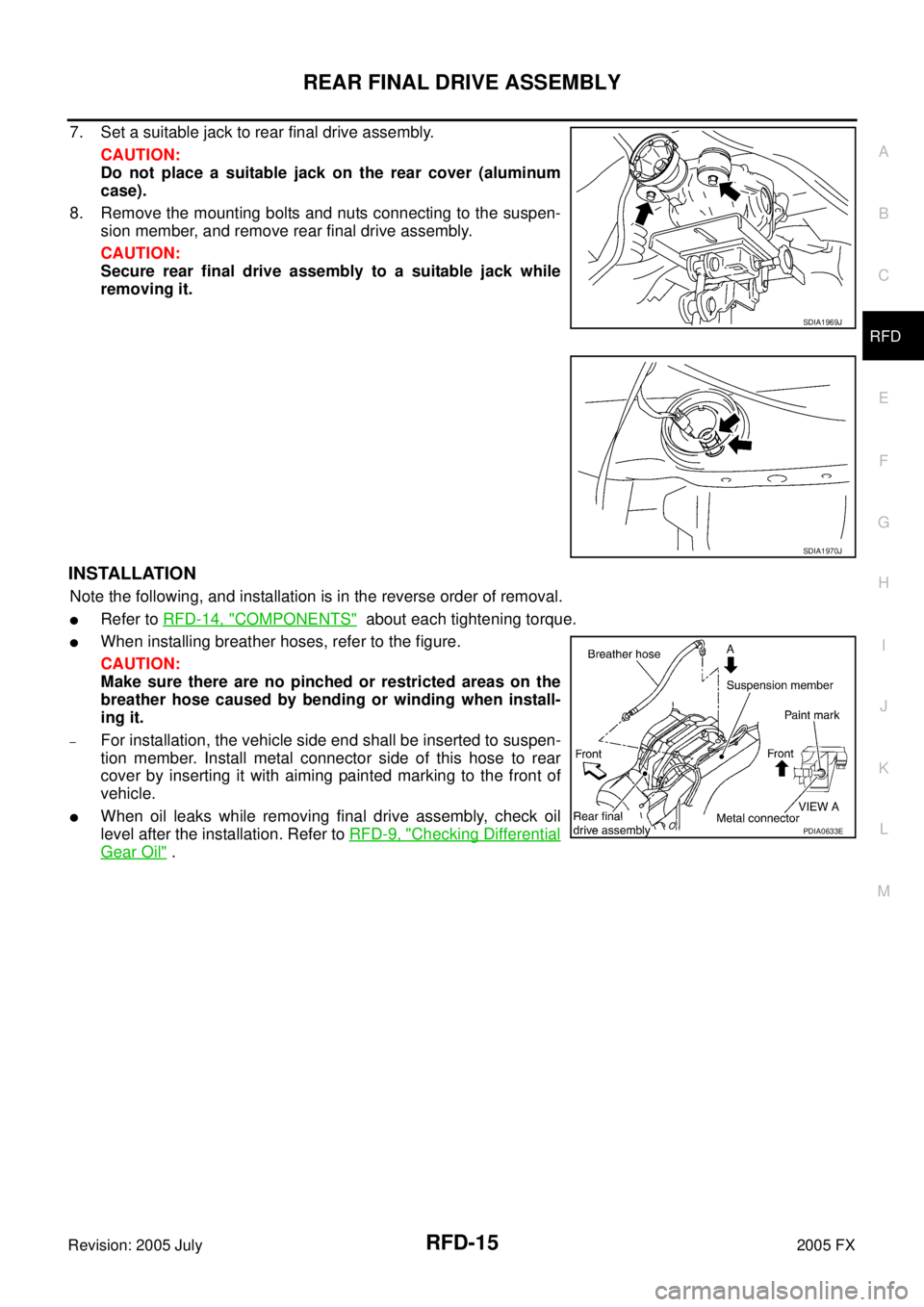
7. Set a suitable jack to rear final drive assembly.
CAUTION:
Do not place a suitable jack on the rear cover (aluminum
case).
8. Remove the mounting bolts and nuts connecting to the suspen- sion member, and remove rear final drive assembly.
CAUTION:
Secure rear final drive assembly to a suitable jack while
removing it.
INSTALLATION
Note the following, and installation is in the reverse order of removal.
�Refer to RFD-14, "COMPONENTS" about each tightening torque.
�When installing breather hoses, refer to the figure.
CAUTION:
Make sure there are no pinched or restricted areas on the
breather hose caused by bending or winding when install-
ing it.
–For installation, the vehicle side end shall be inserted to suspen-
tion member. Install metal connector side of this hose to rear
cover by inserting it with aiming painted marking to the front of
vehicle.
�When oil leaks while removing final drive assembly, check oil
level after the installation. Refer to RFD-9, "
Checking Differential
Gear Oil" .
SDIA1969J
SDIA1970J
PDIA0633E
Page 4386 of 4731
REAR FINAL DRIVE ASSEMBLY RFD-17
C E F
G H
I
J
K L
M A
B
RFD
Revision: 2005 July 2005 FX
ASSEMBLY INSPECTION AND ADJUSTMENT
�Before inspection and adjustment, drain gear oil.
Total Preload Torque
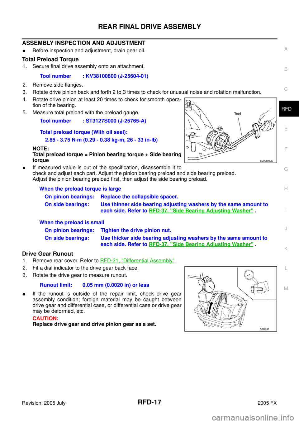
1. Secure final drive assembly onto an attachment.
2. Remove side flanges.
3. Rotate drive pinion back and forth 2 to 3 times to check for unusual noise and rotation malfunction.
4. Rotate drive pinion at least 20 times to check for smooth opera- tion of the bearing.
5. Measure total preload with the preload gauge.
NOTE:
Total preload torque = Pinion bearing torque + Side bearing
torque
�If measured value is out of the specification, disassemble it to
check and adjust each part. Adjust the pinion bearing preload and side bearing preload.
Adjust the pinion bearing preload first, then adjust the side bearing preload.
Drive Gear Runout
1. Remove rear cover. Refer to RFD-21, "Differential Assembly" .
2. Fit a dial indicator to the drive gear back face.
3. Rotate the drive gear to measure runout.
�If the runout is outside of the repair limit, check drive gear
assembly condition; foreign material may be caught between
drive gear and differential case, or differential case or drive gear
may be deformed, etc.
CAUTION:
Replace drive gear and drive pinion gear as a set. Tool number : KV38100800 (J-25604-01)
Tool number : ST3127S000 (J-25765-A)
Total preload torque (With oil seal): 2.85 - 3.75 N·m (0.29 - 0.38 kg-m, 26 - 33 in-lb)
SDIA1007E
When the preload torque is large On pinion bearings: Replace the collapsible spacer.
On side bearings: Use thinner side bearing adjusting washers by the same amount to each side. Refer to RFD-37, "
Side Bearing Adjusting Washer" .
When the preload is small On pinion bearings: Tighten the drive pinion nut.
On side bearings: Use thicker side bearing adjusting washers by the same amount to each side. Refer to RFD-37, "
Side Bearing Adjusting Washer" .
Runout limit: 0.05 mm (0.0020 in) or less
SPD886
Page 4396 of 4731
REAR FINAL DRIVE ASSEMBLY RFD-27
C E F
G H
I
J
K L
M A
B
RFD
Revision: 2005 July 2005 FX
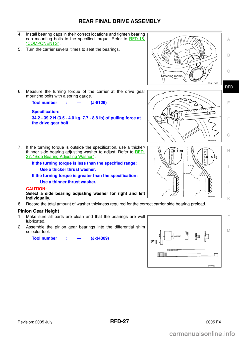
4. Install bearing caps in their correct locations and tighten bearing
cap mounting bolts to the specified torque. Refer to RFD-16,
"COMPONENTS" .
5. Turn the carrier several times to seat the bearings.
6. Measure the turning torque of the carrier at the drive gear mounting bolts with a spring gauge.
7. If the turning torque is outside the specification, use a thicker/ thinner side bearing adjusting washer to adjust. Refer to RFD-
37, "Side Bearing Adjusting Washer" .
CAUTION:
Select a side bearing adjusting washer for right and left
individually.
8. Record the total amount of washer thickness required for the correct carrier side bearing preload.
Pinion Gear Height
1. Make sure all parts are clean and that the bearings are well lubricated.
2. Assemble the pinion gear bearings into the differential shim selector tool.
SDIA1795E
Tool number : — (J-8129)
Specification:
34.2 - 39.2 N (3.5 - 4.0 kg, 7.7 - 8.8 lb) of pulling force at
the drive gear bolt
SPD194A
If the turning torque is less than the specified range:
Use a thicker thrust washer.
If the turning torque is greater than the specification: Use a thinner thrust washer.
SPD772
Tool number : — (J-34309)
SPD769
Page 4397 of 4731
RFD-28
REAR FINAL DRIVE ASSEMBLY
Revision: 2005 July 2005 FX
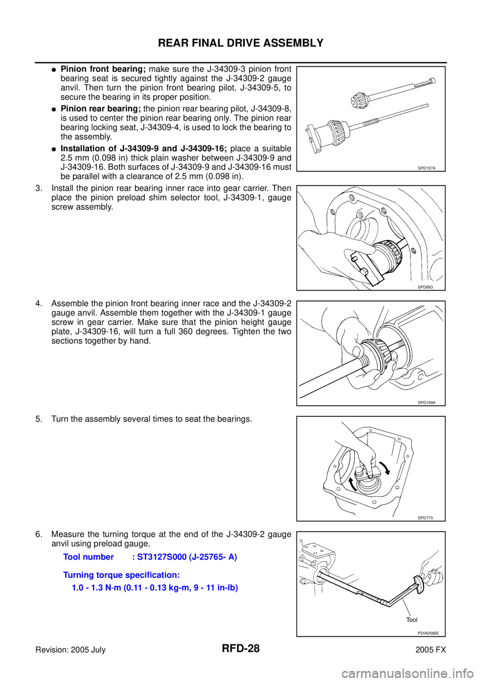
�Pinion front bearing; make sure the J-34309-3 pinion front
bearing seat is secured tightly against the J-34309-2 gauge
anvil. Then turn the pinion front bearing pilot, J-34309-5, to
secure the bearing in its proper position.
�Pinion rear bearing; the pinion rear bearing pilot, J-34309-8,
is used to center the pinion rear bearing only. The pinion rear
bearing locking seat, J-34309-4, is used to lock the bearing to
the assembly.
�Installation of J-34309-9 and J-34309-16; place a suitable
2.5 mm (0.098 in) thick plain washer between J-34309-9 and
J-34309-16. Both surfaces of J-34309-9 and J-34309-16 must
be parallel with a clearance of 2.5 mm (0.098 in).
3. Install the pinion rear bearing inner race into gear carrier. Then place the pinion preload shim selector tool, J-34309-1, gauge
screw assembly.
4. Assemble the pinion front bearing inner race and the J-34309-2 gauge anvil. Assemble them together with the J-34309-1 gauge
screw in gear carrier. Make sure that the pinion height gauge
plate, J-34309-16, will turn a full 360 degrees. Tighten the two
sections together by hand.
5. Turn the assembly several times to seat the bearings.
6. Measure the turning torque at the end of the J-34309-2 gauge anvil using preload gauge.
SPD197A
SPD893
SPD199A
SPD770
Tool number : ST3127S000 (J-25765- A)
Turning torque specification: 1.0 - 1.3 N·m (0.11 - 0.13 kg-m, 9 - 11 in-lb)
PDIA0566E