Page 4647 of 4731

TF-14
TROUBLE DIAGNOSIS
Revision: 2005 July 2005 FX
TROUBLE DIAGNOSISPFP:00004
Fail-Safe FunctionADS000S1
�If any malfunction occurs in AWD electrical system, and control unit detects the malfunction, AWD warn-
ing lamp on combination meter turns ON to indicate system malfunction.
�When AWD warning lamp is ON, vehicle changes to rear-wheel drive or shifting driving force-AWD (Front-
wheels still have some driving torque).
How to Perform Trouble DiagnosisADS000S2
BASIC CONCEPT
�To perform trouble diagnosis, it is the most important to have understanding about vehicle systems (con-
trol and mechanism) thoroughly.
�It is also important to clarify customer complaints before inspec-
tion.
First of all, reproduce symptoms, and understand them fully.
Ask customer about his/her complaints carefully. In some cases,
it will be necessary to check symptoms by driving vehicle with
customer.
CAUTION:
Customers are not professional. It is dangerous to make an
easy guess like "maybe the customer means that...," or
"maybe the customer mentions this symptom".
�It is essential to check symptoms right from the beginning in
order to repair malfunctions completely.
For intermittent malfunctions, reproduce symptoms based on
interview with customer and past examples. Do not perform
inspection on ad hoc basis. Most intermittent malfunctions are
caused by poor contacts. In this case, it will be effective to shake
suspected harness or connector by hand. When repairing with-
out any symptom diagnosis, you cannot judge if malfunctions
have actually been eliminated.
�After completing diagnosis, always erase diagnostic memory.
Refer to TF-23, "
How to Erase Self-Diagnostic Results" .
�For intermittent malfunctions, move harness or harness connec-
tor by hand. Then check for poor contact or reproduced open circuit.
SEF233G
SEF234G
Page 4653 of 4731

TF-20
TROUBLE DIAGNOSIS
Revision: 2005 July 2005 FX
Trouble Diagnosis Chart for SymptomsADS000S3
If AWD warning lamp turns ON, perform self-diagnosis. Refer to TF-22, "SELF-DIAG RESULT MODE" .
NOTE:
Light tight-corner braking symptom may occur depending on driving conditions. This is not malfunction.
AWD Control Unit Input/Output Signal Reference ValuesADS000S4
AWD CONTROL UNIT INSPECTION TABLE
Specifications with CONSULT-II
Symptom Condition Check item Reference page
AWD warning lamp does not turn ON when
the ignition switch is turned to ON.
(AWD warning lamp check) Ignition switch: ON CAN communication line
TF-33
Unified meter and A/C amp.
Unified meter control unit
AWD warning lamp does not turn OFF sev-
eral seconds after engine started. Engine running CAN communication line
TF-33
Power supply and ground for AWD con-
trol unit
Unified meter and A/C amp.
Unified meter control unit
AWD solenoid
AWD actuator relay (integrated in AWD
control unit)
Wheel sensor
Heavy tight-corner braking symptom occurs
when the vehicle is driven and the steering
wheel is turned fully to either side after the
engine is started. (See NOTE.)
�While driving
�Steering wheel is
turned fully to either
sides CAN communication line
TF-35Accelerator pedal position signal
AWD solenoid
Mechanical malfunction of electric con-
trolled coupling (clutch sticking etc.)
Vehicle does not enter AWD mode even
though AWD warning lamp turned to OFF. While driving AWD solenoid
TF-36
Mechanical malfunction of electric con-
trolled coupling (Mechanical engage-
ment of clutch is not possible.)
While driving, AWD warning lamp flashes
rapidly. (When flashing in approx. 1 minute
and then turning OFF.)
Rapid flashing: 2 times/second While driving Protection function is activated due to
heavy load to electric controlled cou-
pling. (AWD system is not malfunction-
ing. Also, optional distribution of torque
sometimes becomes rigid before lamp
flashes rapidly, but it is not malfunction.) TF-37
While driving, AWD warning lamp flashes
slowly. (When continuing to flash until turn-
ing ignition switch OFF)
Slow flashing: 1 time/2 seconds�While driving
�Vehicle speed: 20 km/h
(12 MPH) or more Tire size is different between front and
rear of vehicle. TF-37
Monitored item [Unit] Content Condition Display value
FR RH SENSOR [km/h] or [mph] Wheel speed (Front wheel
right) Vehicle stopped 0.00 km/h (0.00 mph)
Vehicle running
CAUTION:
Check air pressure of tire under
standard condition. Approximately equal to
the indication on speed-
ometer (Inside of ±10%)
FR LH SENSOR [km/h] or [mph] Wheel speed (Front wheel
left) Vehicle stopped 0.00 km/h (0.00 mph)
Vehicle running
CAUTION:
Check air pressure of tire under
standard condition. Approximately equal to
the indication on speed-
ometer (Inside of ±10%)
Page 4670 of 4731

TROUBLE DIAGNOSIS FOR SYMPTOMS TF-37
C E F
G H
I
J
K L
M A
B
TF
Revision: 2005 July 2005 FX
3. SYMPTOM CHECK
Check again.
OK or NG
OK >> INSPECTION END
NG >> Replace electric controlled coupling for mechanical malfunction (mechanical engagement of
clutch is not possible.). Refer to TF-45, "
Disassembly and Assembly" .
While Driving, AWD Warning Lamp Flashes Rapidly (When Flashing in Approx.
1 Minute and Then Turning OFF)
ADS000U1
NOTE:
Rapid flashing: 2 times/second
This symptom protects drivetrain parts when a heavy load is applied to the electric controlled coupling and
multiple disc clutch temperature increases. Also, optional distribution of torque sometimes becomes rigid
before lamp flashes rapidly. Both cases are not malfunction.
When this symptom occurs, stop vehicle and allow it to idle for some times. Flashing will stop and system will
be restored.
While Driving, AWD Warning Lamp Flashes Slowly (When Continuing to Flash
until Turning Ignition Switch OFF)
ADS000U2
NOTE:
Slow flashing: 1 time/2 seconds
DIAGNOSTIC PROCEDURE
1. CHECK TIRE
Check the following.
�Tire pressure
�Wear condition
�Longitudinal tire size (There is no difference between longitudinal tires.)
OK or NG
OK >> GO TO 2.
NG >> Drive at vehicle speed of 20 km/h (12 MPH) or more for 5 seconds or more after repairing or
replacing damaged parts. (Initialize improper size tire information.)
2. CHECK INPUT SIGNAL OF TIRE DIAMETER
With CONSULT-II
1. Start engine.
2. Drive at 20 km/h (12 MPH) or more for approx. 200 seconds.
3. Select “DATA MONITOR” mode for “ALL MODE AWD/4WD” with CONSULT-II.
4. Check monitor “DIS-TIRE MONI”.
Display of
“DIS-TIRE MONI”
“0-4mm”>> INSPECTION END
Except for “0-4mm”>>GO TO 3.
SDIA1900E
Page 4675 of 4731
TF-42
REAR OIL SEAL
Revision: 2005 July 2005 FX
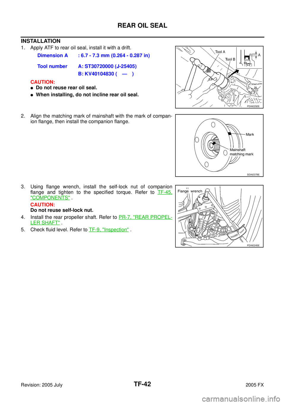
INSTALLATION
1. Apply ATF to rear oil seal, install it with a drift.
CAUTION:
�Do not reuse rear oil seal.
�When installing, do not incline rear oil seal.
2. Align the matching mark of mainshaft with the mark of compan- ion flange, then install the companion flange.
3. Using flange wrench, install the self-lock nut of companion flange and tighten to the specified torque. Refer to TF-45,
"COMPONENTS" .
CAUTION:
Do not reuse self-lock nut.
4. Install the rear propeller shaft. Refer to PR-7, "
REAR PROPEL-
LER SHAFT" .
5. Check fluid level. Refer to TF-9, "
Inspection" .
Dimension A : 6.7 - 7.3 mm (0.264 - 0.287 in)
Tool number A: ST30720000 (J-25405) B: KV40104830 ( — )
PDIA0292E
SDIA2378E
PDIA0245E
Page 4677 of 4731

TF-44
TRANSFER ASSEMBLY
Revision: 2005 July 2005 FX
TRANSFER ASSEMBLYPFP:33100
Removal and InstallationADS000RS
REMOVAL
1. Remove tunnel stay with power tool. Refer to RSU-7, "Components" .
2. Remove exhaust front tube with power tool. Refer to EX-3, "
EXHAUST SYSTEM" .
3. Remove front and rear propeller shaft. Refer to PR-4, "
FRONT PROPELLER SHAFT" and PR-7, "REAR
PROPELLER SHAFT" .
4. Disconnect transfer assembly harness connector and separate harness from transfer assembly.
5. Remove air breather hose. Refer to TF-43, "
AIR BREATHER HOSE" .
6. Support transfer assembly and transmission assembly with a jack.
7. Remove engine rear member with power tool. Refer to EM-112, "
ENGINE ASSEMBLY" (VQ35DE) or
EM-240, "
ENGINE ASSEMBLY" (VK45DE).
8. Remove transfer mounting bolts and separate transfer from transmission. CAUTION:
Secure transfer assembly to a jack.
INSTALLATION
Note the following, and install in the reverse order of removal.
�When installing the transfer to the transmission, install the
mounting bolts following the standard below.
�After the installation, check the fluid level and for fluid leakage.
Refer to TF-9, "
Inspection" .
Bolt No. 1 2 3 4
Quantity 4 3 2 1
Bolt length “ ” mm (in) 75 (2.95) 45 (1.77) 40 (1.57) 30 (1.18)
Tightening torque
N·m (kg-m, ft-lb) 37 (3.8, 27)
SDIA2284E
Page 4686 of 4731
TRANSFER ASSEMBLY TF-53
C E F
G H
I
J
K L
M A
B
TF
Revision: 2005 July 2005 FX
Mainshaft Assembly
1. Install needle bearing to mainshaft.
CAUTION:
Apply ATF to periphery of needle bearing.
2. Install sprocket and electric controlled coupling to mainshaft.
3. Install spacer to main shaft.
4. Install snap ring to mainshaft. CAUTION:
Do not reuse snap ring.
5. Install mainshaft assembly to rear case, then install front case and rear case. Refer to TF-53, "
Front Case and Rear Case" .
Front Case and Rear Case
1. Install breather tube, with plastic hammer.
CAUTION:
Pay attention to the direction of breather tube.
2. Install baffle plate to rear case, and tighten bolt to the specified torque. Refer to TF-45, "
COMPONENTS" .
3. Install rear bearing to rear case, using a drift. CAUTION:
Apply ATF to inside of rear bearing.
PDIA0273E
SDIA1602E
PDIA0274E
Tool number : KV38104010 ( — )
PDIA0275E
Page 4687 of 4731
TF-54
TRANSFER ASSEMBLY
Revision: 2005 July 2005 FX
4. Install snap ring to rear case.
CAUTION:
Do not reuse snap ring.
5. Install mainshaft assembly to rear case, using a drift. CAUTION:
ATF should be applied to contact surface of mainshaft and
rear bearing.
6. Install O-ring to transfer assembly harness connector. CAUTION:
�Do not reuse O-ring.
�Apply ATF to O-ring.
7. Install transfer assembly harness connector into rear case.
8. Install retainer to transfer assembly harness connector.
9. Set temperature sensor and tighten bolt to the specified torque. Refer to TF-45, "
COMPONENTS" .
10. Hold electric controlled coupling harness with oil cover hold plate, install oil cover to rear case, and tighten bolt to the speci-
fied torque. Refer to TF-45, "
COMPONENTS" .
CAUTION:
The harness should be guided by a cut portion.
PDIA0263E
Tool number : ST35321000 ( — )
SDIA2368E
SDIA1597E
SDIA2404E
Page 4689 of 4731
TF-56
TRANSFER ASSEMBLY
Revision: 2005 July 2005 FX
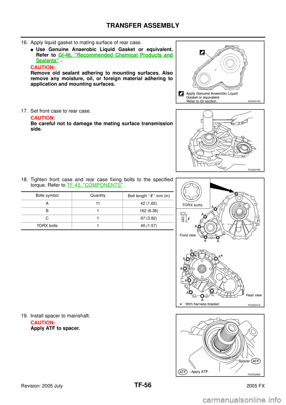
16. Apply liquid gasket to mating surface of rear case.
�Use Genuine Anaerobic Liquid Gasket or equivalent.
Refer to GI-48, "
Recommended Chemical Products and
Sealants" .
CAUTION:
Remove old sealant adhering to mounting surfaces. Also
remove any moisture, oil, or foreign material adhering to
application and mounting surfaces.
17. Set front case to rear case. CAUTION:
Be careful not to damage the mating surface transmission
side.
18. Tighten front case and rear case fixing bolts to the specified torque. Refer to TF-45, "
COMPONENTS" .
19. Install spacer to mainshaft. CAUTION:
Apply ATF to spacer.
SDIA2312E
PDIA0279E
Bolts symbol Quantity Bolt length “ ” mm (in)
A 11 42 (1.65)
B 1 162 (6.38)
C 1 97 (3.82)
TORX bolts 1 40 (1.57)
PDIA0251E
PDIA0260E