Page 4303 of 4731
, install rear cover to gear housing assembly.
10. Confirm projection on rear cover cap nearly fit wi")
PS-28
POWER STEERING GEAR AND LINKAGE
Revision: 2005 July 2005 FX
9. Use a rear cover wrench (SST), install rear cover to gear housing assembly.
10. Confirm projection on rear cover cap nearly fit with marking position on gear housing assembly.
11 . A p p l y t h r e a d l o c k i n g a d h e s i v e ( T h r e e B o u n d T B 1111 B o r e q u i v - alent. Refer to GI-48
) to the thread of adjusting screw to the
adjusting screw height from gear housing assembly. The adjust-
ing screw height is the same as it was measured in the overhaul
in advance.
12. Rotate pinion ten times whole range of rack so that parts get to fit with each other.
13. Measure pinion rotating torque within from –180 ° to +180 °,
make preload gauge (SST) and torque adapter (SST) in rack
neutral position, then hold preload gauge (SST) at maximum
torque.
14. After loosening adjusting screw once, tighten it again with torque of 5.4 N·m (0.55 kg-m, 48 in-lb). After that loosen it within 20 ° to
40 °.
15. Measure pinion rotating torque with torque adapter (SST) and preload gauge (SST), then confirm whether it's reading is within
the specified value. If the reading is not within the specified
value, readjust screw angle with adjusting screw. Change gear
assembly to new one, if the reading is still not within the speci-
fied value or the rotating torque of adjusting screw is less than 5
N·m (0.51 kg-m, 44 in-lb).
16. Turn pinion fully to the end of the left with inner socket to gear housing assembly.
17. Set dial gauge to rack as shown in the figure. Measure vertical movement of rack when pinion is turned counterclockwise with
torque of 19.6 N·m (2.0 kg-m, 14 ft-lb). Check reading is within
the specified value. If reading is outside of the specification,
readjust screw angle with adjusting screw. If reading is still out-
side of specification, or if the rotating torque of adjusting screw is
less than 5 N·m (0.51 kg-m, 44 in-lb), replace steering gear
assembly.
SGIA0568E
SGIA0483E
Pinion rotating torque:
Around neutral position (within ±100 °)
Average “A”:
0.8 − 2.0 N·m (0.08 − 0.20 kg-m, 7 − 18 in-lb)
Other than above (more than ±100 °)
Maximum variation “B”:
2.3 N·m (0.23 kg-m, 20 in-lb)
SGIA0160E
SGIA0484E
Page 4305 of 4731
PS-30
POWER STEERING GEAR AND LINKAGE
Revision: 2005 July 2005 FX
24. Tighten lightly inner socket in specified length “L”, then tighten
lock nut at specified torque. Refer to PS-22, "
Disassembly and
Assembly" . Reconfirm if inner socket length is within limit of
specified length “L”.
CAUTION:
Perform toe-in adjustment after this procedure. Length
achieved after toe-in adjustment is not necessary value
given here. Inner socket length “L” : 135.2 mm (5.32 in)
SGIA0167E
Page 4308 of 4731
. Refer to PS-41,
\"")
POWER STEERING OIL PUMP PS-33
C
D E
F
H I
J
K L
M A
B
PS
Revision: 2005 July 2005 FX
4. Remove piping of high pressure and low pressure (drain fluid from their pipings). Refer to PS-41,
"HYDRAULIC LINE" .
5. Remove mounting bolts, then remove power steering pump.
INSTALLATION
Refer to PS-41, "HYDRAULIC LINE" for tightening torque. Install in the reverse order removal.
�After installation, adjust belt tension. Refer to EM-15, "DRIVE BELTS" .
�After installation, bleed air. Refer to PS-8, "Air Bleeding Hydraulic System" .
Removal and Installation (VK45DE Models)AGS000HJ
REMOVAL
1. Remove undercover from vehicle with power tool.
2. Remove power steering oil pump belt from auto tensioner. Refer to EM-173, "
DRIVE BELTS" .
3. Drain power steering fluid from reservoir tank.
4. Remove piping of high pressure and low pressure from power steering oil pump (drain fluid from their pip- ings). Refer to PS-41, "
HYDRAULIC LINE" .
5. Remove mounting bolts, then remove power steering pump.
INSTALLATION
Refer to PS-41, "HYDRAULIC LINE" for tightening torque. Install in the reverse order removal.
After installation, bleed air. Refer to PS-8, "
Air Bleeding Hydraulic System" .
NOTE:
Adjustment of belt tension is no necessary because engine of this model equips auto tensioner.
Disassembly and Assembly (VQ35DE Models)AGS000HE
INSPECTION BEFORE DISASSEMBLY
Disassemble power steering oil pump only if the following items are found.
�Oil leakage from oil pump
�Deformed or damaged pulley
1. Rear cover 2. Teflon ring 3. O-ring
4. Rear side plate 5. Rotor snap ring 6. Dowel pin
7. Cam ring 8. Rotor 9. Vane
10. Cartridge 11. Front side plate 12. O-ring
13. Flow control valve A 14. Spring 15. Flow control valve B assembly
16. Body assembly 17. Oil seal 18. Pulley
19. O-ring 20. Suction pipe 21. Bracket
SGIA0622E
Page 4311 of 4731
 box, install rotor snap
ring to slot")
PS-36
POWER STEERING OIL PUMP
Revision: 2005 July 2005 FX
8. Install vane to rotor with facing the round portion outside.
9. Using a hammer and a 10 mm (0.39 in) box, install rotor snap
ring to slot in pulley shaft.
NOTE:
Do not reuse snap ring.
CAUTION:
Be careful not to damage rotor and pulley shaft.
10. Match dowel pin A on flow control valve A, shown in the figure, with cutout B of rear side plate and install rear side plate to car-
tridge.
11. Apply Genuine Nissan PSF or equivalent to O-ring and install O- ring into rear side plate.
NOTE:
Do not reuse O-ring.
12. Apply Genuine Nissan PSF or equivalent to Teflon ring and Install Teflon ring into rear side plate.
NOTE:
Do not reuse Teflon ring.
13. Position rear cover on body assembly and tighten mounting bolts to specified torque.
14. Apply Genuine Nissan PSF or equivalent to O-ring and install O-ring into suction pipe. NOTE:
Do not reuse O-ring.
15. Install suction pipe into body assembly.
16. Install bracket to body assembly and tighten mounting bolts to specified torque.
SST843A
SGIA0063E
SGIA0530E
Page 4315 of 4731
PS-40
POWER STEERING OIL PUMP
Revision: 2005 July 2005 FX
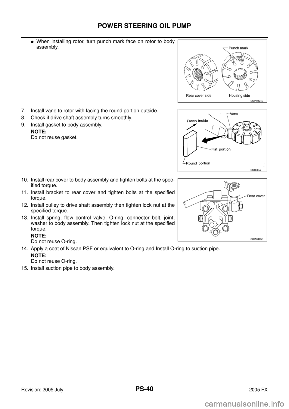
�When installing rotor, turn punch mark face on rotor to body
assembly.
7. Install vane to rotor with facing the round portion outside.
8. Check if drive shaft assembly turns smoothly.
9. Install gasket to body assembly. NOTE:
Do not reuse gasket.
10. Install rear cover to body assembly and tighten bolts at the spec- ified torque.
11. Install bracket to rear cover and tighten bolts at the specified torque.
12. Install pulley to drive shaft assembly then tighten lock nut at the specified torque.
13. Install spring, flow control valve, O-ring, connector bolt, joint, washer to body assembly. Then tighten lock nut at the specified
torque.
NOTE:
Do not reuse O-ring.
14. Apply a coat of Nissan PSF or equivalent to O-ring and Install O-ring to suction pipe. NOTE:
Do not reuse O-ring.
15. Install suction pipe to body assembly.
SGIA0424E
SST843A
SGIA0425E
Page 4318 of 4731
HYDRAULIC LINE PS-43
C
D E
F
H I
J
K L
M A
B
PS
Revision: 2005 July 2005 FX
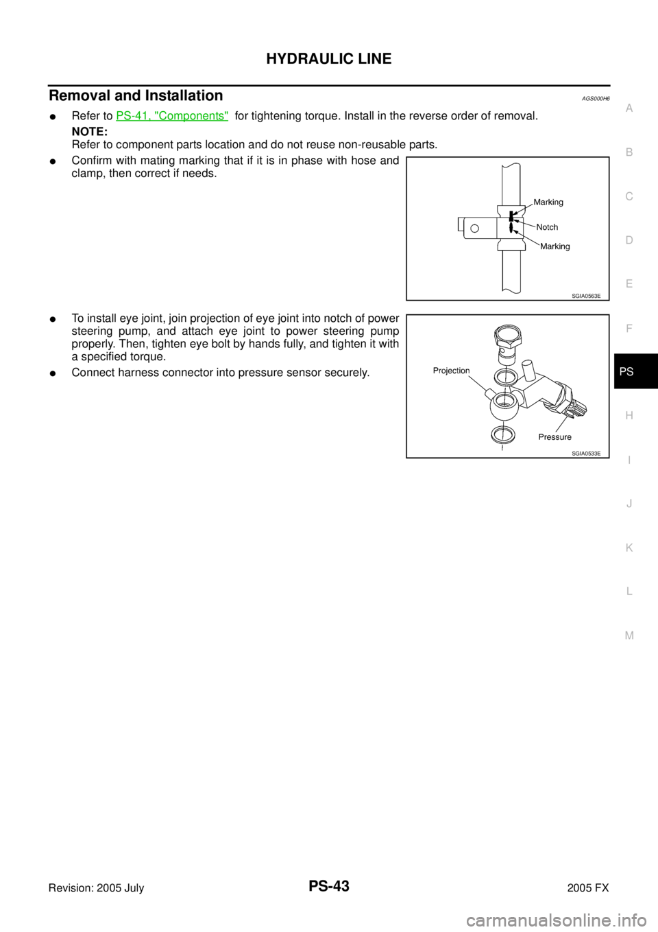
Removal and InstallationAGS000H6
�Refer to PS-41, "Components" for tightening torque. Install in the reverse order of removal.
NOTE:
Refer to component parts location and do not reuse non-reusable parts.
�Confirm with mating marking that if it is in phase with hose and
clamp, then correct if needs.
�To install eye joint, join projection of eye joint into notch of power
steering pump, and attach eye joint to power steering pump
properly. Then, tighten eye bolt by hands fully, and tighten it with
a specified torque.
�Connect harness connector into pressure sensor securely.
SGIA0563E
SGIA0533E
Page 4320 of 4731
HYDRAULIC LINE PS-45
C
D E
F
H I
J
K L
M A
B
PS
Revision: 2005 July 2005 FX
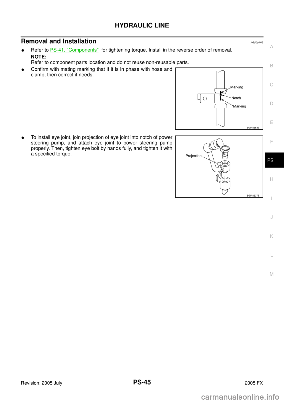
Removal and InstallationAGS000HG
�Refer to PS-41, "Components" for tightening torque. Install in the reverse order of removal.
NOTE:
Refer to component parts location and do not reuse non-reusable parts.
�Confirm with mating marking that if it is in phase with hose and
clamp, then correct if needs.
�To install eye joint, join projection of eye joint into notch of power
steering pump, and attach eye joint to power steering pump
properly. Then, tighten eye bolt by hands fully, and tighten it with
a specified torque.
SGIA0563E
SGIA0537E
Page 4321 of 4731

Revision: 2005 July 2005 FX
SERVICE DATA AND SPECIFICATIONS (SDS)PFP:00030
Steering WheelAGS000H7
Steering AngleAGS000H8
Steering ColumnAGS000H9
Steering Ou")
PS-46
SERVICE DATA AND SPECIFICATIONS (SDS)
Revision: 2005 July 2005 FX
SERVICE DATA AND SPECIFICATIONS (SDS)PFP:00030
Steering WheelAGS000H7
Steering AngleAGS000H8
Steering ColumnAGS000H9
Steering Outer Socket and Inner SocketAGS000HA
End play of the axle direction for steering wheel 0 mm (0 in)
Steering wheel play on the outer circumference 0 − 35 mm (0 − 1.38 in)
Inner wheel
Degree minute (Decimal degree) Minimum 32
°00 ′ (32.0 °)
Nominal 35 °00 ′ (35.0 °)
Maximum 36 °00 ′ (36.0 °)
Outer wheel
Degree minute (Decimal degree) Nominal 30
°00 ′ (30.0 °)
Steering column length “ L1 ” 572 mm (22.52 in)
SGIA0556E
Steering gear type PR26AM
Tie-rod ball joint outer socket Swinging torque 0.3
− 2.9 N·m (0.03 − 0.29 kg-m, 3 − 25 in-lb)
Measurement on spring balance
�Measuring point: cotter pin hole of stud 4.84
− 46.7 N (0.5 − 4.8 kg, 1.0 − 10 lb)
Rotating torque 0.3 − 2.9 N·m (0.03 − 0.29 kg-m, 3 − 25 in-lb)
Axial end play 0.5 mm (0.02 in) or less
Tie-rod ball joint inner socket Swinging torque 1.0
− 7.8 N·m (0.11 − 0.79 kg-m, 9 − 69 in-lb)
Measurement on spring balance
�Measuring point: L mark see below,
L=83.2 mm (3.28 in). 12.1
− 93.7 N (1.2 − 9.6 kg, 3.0 − 21 lb)
Axial end play 0.2 mm (0.01 in) or less
SGIA0358E