Page 549 of 4731
ATC-112
TROUBLE DIAGNOSIS
Revision: 2005 July 2005 FX
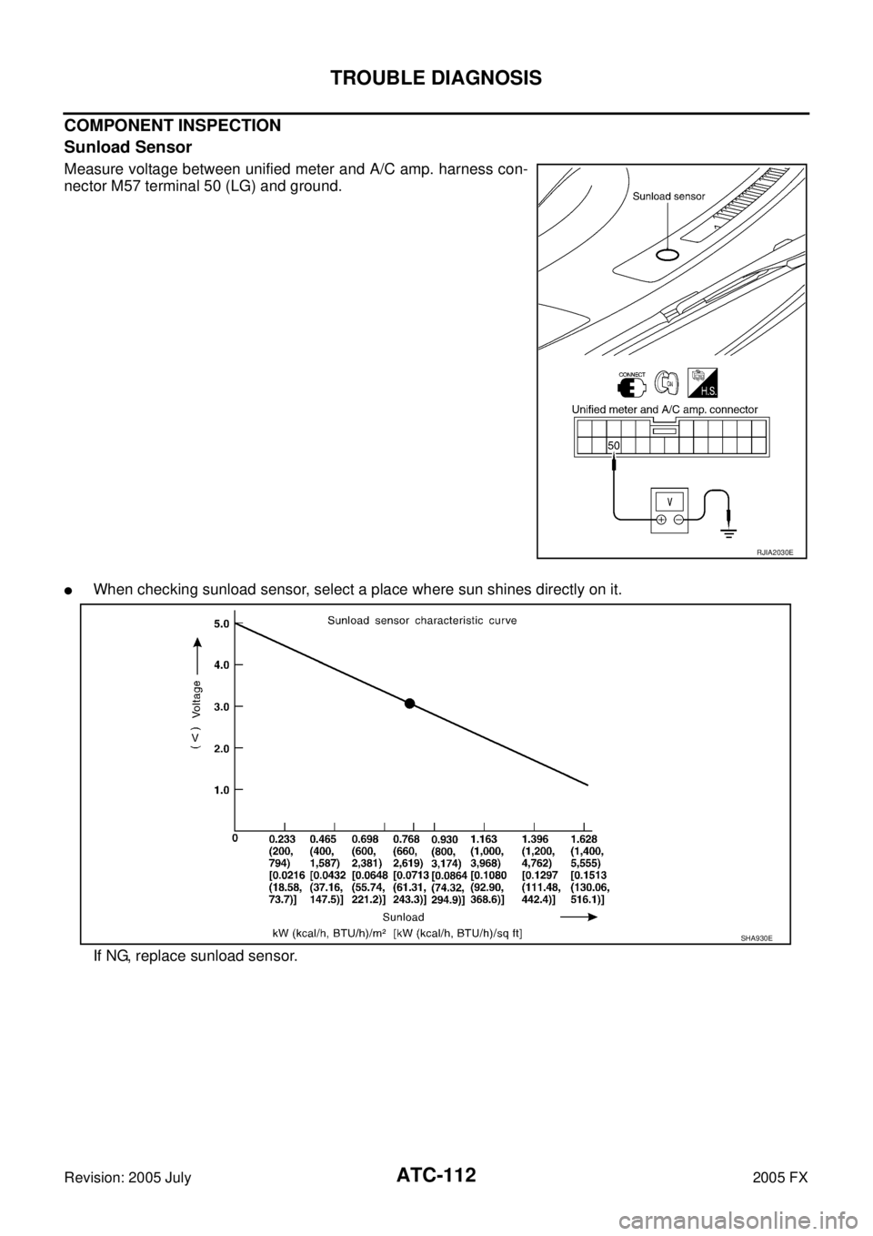
COMPONENT INSPECTION
Sunload Sensor
Measure voltage between unified meter and A/C amp. harness con-
nector M57 terminal 50 (LG) and ground.
�When checking sunload sensor, select a place where sun shines directly on it.
If NG, replace sunload sensor.
RJIA2030E
SHA930E
Page 550 of 4731

TROUBLE DIAGNOSIS ATC-113
C
D E
F
G H
I
K L
M A
B
AT C
Revision: 2005 July 2005 FX
Intake Sensor CircuitAJS00157
COMPONENT DESCRIPTION
Intake Sensor
The intake sensor is located on the heater & cooling unit assembly. It
converts temperature of air after it passes through the evaporator
into a resistance value which is then input to the unified meter and A/
C amp.
DIAGNOSIS PROCEDURE FOR INTAKE SENSOR
SYMPTOM: Intake sensor circuit is open or shorted. (24 or −24 is
indicated on unified meter and A/C amp. as a result of performing
self-diagnosis STEP-2.)
1. CHECK VOLTAGE BETWEEN INTAKE SENSOR AND GROUND
1. Disconnect intake sensor connector.
2. Turn ignition switch ON.
3. Check voltage between intake sensor harness connector M254 terminal 2 (R) and ground.
OK or NG
OK >> GO TO 2.
NG >> GO TO 4.
2. CHECK CIRCUIT CONTINUITY BETWEEN INTAKE SENSOR AND UNIFIED METER AND A/C AMP.
1. Turn ignition switch OFF.
2. Disconnect unified meter and A/C amp. connector.
3. Check continuity between intake sensor harness connector M254 terminal 1 (W) and unified meter and A/C amp. harness
connector M57 terminal 49 (W/G).
OK or NG
OK >> GO TO 3.
NG >> Repair harness or connector.
RJIA0928E
RJIA1458E
2 – Ground : Approx. 5 V
RJIA2031E
1 – 49 : Continuity should exist.
RJIA2032E
Page 551 of 4731

ATC-114
TROUBLE DIAGNOSIS
Revision: 2005 July 2005 FX
3. CHECK INTAKE SENSOR
Refer to AT C - 11 4 , "
Intake Sensor" .
OK or NG
OK >> 1. Replace unified meter and A/C amp. 2. Go to self-diagnosis AT C - 5 4 , "
FUNCTION CONFIRMATION PROCEDURE" and perform self-
diagnosis STEP-2. Confirm that code No. 20 is displayed.
NG >> 1. Replace intake sensor. 2. Go to self-diagnosis AT C - 5 4 , "
FUNCTION CONFIRMATION PROCEDURE" and perform self-
diagnosis STEP-2. Confirm that code No. 20 is displayed.
4. CHECK CIRCUIT CONTINUITY BETWEEN INTAKE SENSOR AND UNIFIED METER AND A/C AMP.
1. Turn ignition switch OFF.
2. Disconnect unified meter and A/C amp. connector.
3. Check continuity between intake sensor harness connector M254 terminal 2 (R) and unified meter and A/C amp. harness
connector M57 terminal 41 (P).
4. Check continuity between intake sensor harness connector M254 terminal 2 (R) and ground.
OK or NG
OK >> 1. Replace unified meter and A/C amp. 2. Go to self-diagnosis AT C - 5 4 , "
FUNCTION CONFIRMATION PROCEDURE" and perform self-
diagnosis STEP-2. Confirm that code No. 20 is displayed.
NG >> Repair harness or connector.
COMPONENT INSPECTION
Intake Sensor
After disconnecting intake sensor connector M254, measure resis-
tance between terminals 1 and 2 at sensor side, using the table
below.
If NG, replace intake sensor. 2 – 41 : Continuity should exist.
2 – Ground : Continuity should not exist.
RJIA2033E
Temperature °C ( °F) Resistance k Ω
− 15 (5) 12.34
− 10 (14) 9.62
− 5 (23) 7.56
0 (32) 6.00
5 (41) 4.80
10 (50) 3.87
15 (59) 3.15
20 (68) 2.57
25 (77) 2.12
30 (86) 1.76
35 (95) 1.47
40 (104) 1.23 45 (113) 1.04
RJIA2034E
Page 554 of 4731
AMBIENT SENSOR ATC-117
C
D E
F
G H
I
K L
M A
B
AT C
Revision: 2005 July 2005 FX
AMBIENT SENSORPFP:27722
Removal and InstallationAJS0015A
REMOVAL
1. Remove front grille. Refer to EI-22, "FRONT GRILLE" .
2. Disconnect ambient sensor connector, and then remove ambi- ent sensor.
INSTALLATION
Installation is basically the reverse order of removal.
RJIA2016E
Page 555 of 4731
ATC-118
IN-VEHICLE SENSOR
Revision: 2005 July 2005 FX
IN-VEHICLE SENSORPFP:27720
Removal and InstallationAJS0015B
REMOVAL
1. Remove instrument driver lower panel. Refer to IP-11, "Removal and Installation" .
2. Remove mounting screw, and then remove in-vehicle sensor.
INSTALLATION
Installation is basically the reverse order of removal.
RJIA2036E
Page 556 of 4731
SUNLOAD SENSOR ATC-119
C
D E
F
G H
I
K L
M A
B
AT C
Revision: 2005 July 2005 FX
SUNLOAD SENSORPFP:27721
Removal and InstallationAJS0015C
REMOVAL
1. Remove front defroster grille (right side). Refer to IP-11, "Removal and Installation" .
2. Disconnect sunload sensor connector, and then remove the sunload sensor.
INSTALLATION
Installation is basically the reverse order of removal.
RJIA2026E
Page 557 of 4731

ATC-120
INTAKE SENSOR
Revision: 2005 July 2005 FX
INTAKE SENSORPFP:27723
Removal and InstallationAJS0015D
REMOVAL
1. Remove low-pressure pipe 2 and high-pressure pipe 3. Refer to ATC-152, "Removal and Installation of
Low-Pressure Pipe 2 and High-Pressure Pipe 3" .
CAUTION:
Cap or wrap the joint of the pipe with suitable material such as vinyl tape to avoid the entry of air.
2. Slide evaporator to passenger side, and then remove intake sensor.
INSTALLATION
Installation is basically the reverse order of removal.
CAUTION:
�Replace O-rings of A/C piping with new ones, and then apply compressor oil to it when installing
it.
�Mark the mounting position of intake sensor bracket prior to removal so that the reinstalled sen-
sor can be located in the same position.
�Connection point for female-side piping is thin. So, when inserting male-side piping, take care not
to deform female-side piping. Slowly insert in axial direction.
�Insert one-touch joint connection point securely until it clicks.
�After piping has been connected, pull male-side piping by hand to make sure piping does not
come off.
�When recharging refrigerant, check for leaks.
RJIA0928E
Page 566 of 4731
HEATER & COOLING UNIT ASSEMBLY ATC-129
C
D E
F
G H
I
K L
M A
B
AT C
Revision: 2005 July 2005 FX
Disassembly and AssemblyAJS0015K
1. Heater pipe grommet 2. Heater core 3. Heater pipe cover
4. Aspirator 5. Aspirator hose 6. Air mix door motor (driver side)
7. Air mix door (slide door) 8. Max. cool door link 9. Max. cool door lever
10. Ventilator door lever 11. Ventilator door link 12. Air mix door motor (passenger side)
13. Intake sensor bracket 14. Intake sensor 15. Foot duct (right)
16. Evaporator cover 17. Evaporator cover adaptor 18. Heater pipe bracket
RJIA2045E